EP0806613A2 - Plaque en matière plastique pour chauffage par le sol - Google Patents
Plaque en matière plastique pour chauffage par le sol Download PDFInfo
- Publication number
- EP0806613A2 EP0806613A2 EP97107151A EP97107151A EP0806613A2 EP 0806613 A2 EP0806613 A2 EP 0806613A2 EP 97107151 A EP97107151 A EP 97107151A EP 97107151 A EP97107151 A EP 97107151A EP 0806613 A2 EP0806613 A2 EP 0806613A2
- Authority
- EP
- European Patent Office
- Prior art keywords
- plastic plate
- aluminum foil
- plates
- plastic
- underfloor heating
- Prior art date
- Legal status (The legal status is an assumption and is not a legal conclusion. Google has not performed a legal analysis and makes no representation as to the accuracy of the status listed.)
- Withdrawn
Links
Images

Classifications
-
- F—MECHANICAL ENGINEERING; LIGHTING; HEATING; WEAPONS; BLASTING
- F24—HEATING; RANGES; VENTILATING
- F24D—DOMESTIC- OR SPACE-HEATING SYSTEMS, e.g. CENTRAL HEATING SYSTEMS; DOMESTIC HOT-WATER SUPPLY SYSTEMS; ELEMENTS OR COMPONENTS THEREFOR
- F24D3/00—Hot-water central heating systems
- F24D3/12—Tube and panel arrangements for ceiling, wall, or underfloor heating
- F24D3/14—Tube and panel arrangements for ceiling, wall, or underfloor heating incorporated in a ceiling, wall or floor
-
- F—MECHANICAL ENGINEERING; LIGHTING; HEATING; WEAPONS; BLASTING
- F24—HEATING; RANGES; VENTILATING
- F24D—DOMESTIC- OR SPACE-HEATING SYSTEMS, e.g. CENTRAL HEATING SYSTEMS; DOMESTIC HOT-WATER SUPPLY SYSTEMS; ELEMENTS OR COMPONENTS THEREFOR
- F24D3/00—Hot-water central heating systems
- F24D3/12—Tube and panel arrangements for ceiling, wall, or underfloor heating
- F24D3/14—Tube and panel arrangements for ceiling, wall, or underfloor heating incorporated in a ceiling, wall or floor
- F24D3/148—Tube and panel arrangements for ceiling, wall, or underfloor heating incorporated in a ceiling, wall or floor with heat spreading plates
-
- Y—GENERAL TAGGING OF NEW TECHNOLOGICAL DEVELOPMENTS; GENERAL TAGGING OF CROSS-SECTIONAL TECHNOLOGIES SPANNING OVER SEVERAL SECTIONS OF THE IPC; TECHNICAL SUBJECTS COVERED BY FORMER USPC CROSS-REFERENCE ART COLLECTIONS [XRACs] AND DIGESTS
- Y02—TECHNOLOGIES OR APPLICATIONS FOR MITIGATION OR ADAPTATION AGAINST CLIMATE CHANGE
- Y02B—CLIMATE CHANGE MITIGATION TECHNOLOGIES RELATED TO BUILDINGS, e.g. HOUSING, HOUSE APPLIANCES OR RELATED END-USER APPLICATIONS
- Y02B30/00—Energy efficient heating, ventilation or air conditioning [HVAC]
Definitions
- the invention relates to a plastic plate for underfloor heating with embossed channels for the clamped reception of the underfloor heating pipes.
- Plastic plates for underfloor heating are known in different designs. Plates made of plastic, e.g. Polystyrene, known, which have on their surface facing outward clamping cams, between which the underfloor heating pipes can be clamped. Sheets are also known which have a reflective film, e.g. an aluminum foil, which is usually laminated there. In many cases, especially in the edge areas of the rooms in which the underfloor heating systems are installed, the plastic plates have to be trimmed to cover the entire floor area, which is particularly time-consuming if, as is often desired, the reflective films are comparatively strong are executed.
- the goal is therefore to increase laying comfort in particular of the present invention, the quality of the plastic floor heating panels should not be restricted.
- this object is achieved according to the invention in that the surface of the plastic plate facing upwards in the laying position is provided with a plurality of aluminum foil plates arranged next to one another in a tile-like manner, which are adapted to the surface contour of the plastic plate including the pipe ducts .
- this reflective foil consists of individual, tile-like elements lying next to each other, it is possible with simple means to cut such plastic sheets to the desired sizes, since a separating knife usually does not more the aluminum foil itself has to cut.
- joints are provided between the aluminum foil plates, it being particularly advantageous that the joints are provided with perforations or the like to form predetermined breaking points of the plastic plates, as is also provided by the invention in an embodiment.
- material-thinned areas or material bridges can also be provided in the foam plastic plate, it is possible to break out individual pieces from the plastic plate in a kind of chocolate bar without the need for special tools, so that the plastic plates are quick and easy can be relocated.
- burrs can occur, especially in the inlet and outlet areas of the pipe ducts, which are later pressed into the heating pipes, which are often or generally manufactured as plastic pipes themselves. Since the heating pipes are subject to longitudinal expansion in the event of temperature fluctuations, chafing points can occur here, which endanger the heating pipes.
- the invention provides in a further embodiment that the inlet and outlet areas of the pipe ducts on the aluminum foil plates are provided with inlet and outlet curves that point towards the plastic plate. This reliably prevents burrs on the edges of the aluminum foil plates.
- the invention also provides that the aluminum foil plates are arranged on plastic plates in different grid dimensions.
- eight aluminum foil plates or sixteen aluminum foil plates can be arranged on a 100 X 500 mm plate, for example, which in the first case can have a dimension of 240: 240 mm, in the second case a dimension of 240: 115 mm, so that joint widths of 10 mm and edge distances of 5 mm result.
- the invention also provides that the aluminum foil plates are equipped on their side facing the plastic plate with a PE-lacquered layer, and it can also be provided that the PE-coated aluminum foil plates are firmly connected to the underlying plastic plate, in particular made of polystyrene, by briefly applying heat.
- the plastic plate is made, for example, of a foam plastic, such as polystyrene.
- a foam plastic such as polystyrene.
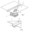
- it has two longitudinal channels 2 and is equipped with aluminum foil plates 3 arranged next to one another in the manner of tiles, in the example shown with eight such plates.
- the plates 3 are shown exaggerated in their thickness in Fig. 2 for better illustration. Such a plate is also shown enlarged in FIG. 3.
- joints 4 between the plates which can be provided with a perforation 5, in order to enable easy breaking off of individual plates 3 or a combination of several plates, as is possible with a chocolate bar.
- Such an aluminum plate 3 is also equipped with a central pipe duct 2a, which is in the corresponding Pipe channel 2 of the plastic plate 1 is inserted in a form-fitting manner.
- the edge of the channel shown in dashed lines in FIG. 4 and labeled 6, is bent downwards, this area is pressed into the foam plastic plate 1 during lamination. This ensures that the inlet and outlet area into the aluminum plates 3 does not represent any damage potential for the heating pipes to come in, sharp edges do not occur here, so that the inserted pipe can move longitudinally with temperature fluctuations without any problems.
- Fig. 3 it is finally indicated that according to a variant of the invention, the aluminum foil plates on their side facing the plastic plate 1 with a hot melt adhesive coating, e.g. a PE lacquer layer 7, which can be connected to the polystyrene plate 1 by the action of heat, symbolically indicated by an iron 8.
- a hot melt adhesive coating e.g. a PE lacquer layer 7
- an iron 8 symbolically indicated by an iron 8.
- the described embodiment of the invention can be modified in many ways without departing from the basic idea.
- the invention is particularly so not limited to the number of aluminum foil plates per plastic plate unit shown here, as already mentioned above, nor to the straight course of the pipe channels 2 or 2a shown here.
- curvatures can also be provided, and the foil plates can also be provided for nub or cam plates u.
- nub or cam plates can also be provided for nub or cam plates u.
Landscapes
- Engineering & Computer Science (AREA)
- Physics & Mathematics (AREA)
- Thermal Sciences (AREA)
- Chemical & Material Sciences (AREA)
- Combustion & Propulsion (AREA)
- Mechanical Engineering (AREA)
- General Engineering & Computer Science (AREA)
- Steam Or Hot-Water Central Heating Systems (AREA)
- Floor Finish (AREA)
Applications Claiming Priority (2)
| Application Number | Priority Date | Filing Date | Title |
|---|---|---|---|
| DE29608258U | 1996-05-07 | ||
| DE29608258U DE29608258U1 (de) | 1996-05-07 | 1996-05-07 | Kunststoffplatte für Fußbodenheizungen |
Publications (2)
| Publication Number | Publication Date |
|---|---|
| EP0806613A2 true EP0806613A2 (fr) | 1997-11-12 |
| EP0806613A3 EP0806613A3 (fr) | 1998-11-11 |
Family
ID=8023656
Family Applications (1)
| Application Number | Title | Priority Date | Filing Date |
|---|---|---|---|
| EP97107151A Withdrawn EP0806613A3 (fr) | 1996-05-07 | 1997-04-30 | Plaque en matière plastique pour chauffage par le sol |
Country Status (2)
| Country | Link |
|---|---|
| EP (1) | EP0806613A3 (fr) |
| DE (1) | DE29608258U1 (fr) |
Cited By (2)
| Publication number | Priority date | Publication date | Assignee | Title |
|---|---|---|---|---|
| WO2005064240A1 (fr) * | 2003-12-10 | 2005-07-14 | Dansk Varmekabel Aps | Systeme de chauffage par le sol, en particulier systeme electrique de chauffage par le sol |
| US12044016B2 (en) | 2017-03-09 | 2024-07-23 | Schluter Systems L.P. | Uncoupling mat with heating elements |
Families Citing this family (8)
| Publication number | Priority date | Publication date | Assignee | Title |
|---|---|---|---|---|
| GB2321302A (en) * | 1997-01-20 | 1998-07-22 | John Lipscomb | Modular heat exchanger |
| DE202005010756U1 (de) * | 2005-07-08 | 2006-11-16 | Uponor Innovation Ab | Wärmeleitelement für eine Flächenheizung oder -kühlung |
| DE102012012544A1 (de) | 2012-06-26 | 2014-01-02 | herotec GmbH Flächenheizung | Verfahren zur Beheizung von Fußböden |
| GB2513863B (en) * | 2013-05-07 | 2019-04-03 | Solfex Ltd | Support system |
| GB2569238B (en) * | 2013-05-07 | 2019-09-11 | Solfex Ltd | Support system |
| AT515868B1 (de) * | 2014-05-23 | 2016-03-15 | Hinrichs Karl Heinz Dipl Ing | Mobile Fußboden-Heizmatten |
| DE202018006493U1 (de) | 2017-10-19 | 2020-09-09 | herotec GmbH Flächenheizung | Dämmschicht für eine Flächentemperiervorrichtung und thermisch leitende Lage für eine Dämmschicht |
| DE202023100345U1 (de) | 2023-01-25 | 2024-04-26 | herotec GmbH Flächenheizung | Dämmschicht für eine Flächentemperiervorrichtung und thermisch leitende Lage für eine Dämmschicht |
Family Cites Families (7)
| Publication number | Priority date | Publication date | Assignee | Title |
|---|---|---|---|---|
| DE2456836C3 (de) * | 1974-12-02 | 1979-02-01 | Franz-Josef 4434 Ochtrup Hagemann | Vorgefertigtes Einbauelement für Flüssigkeits-Flächenheizungen |
| DE2932551C2 (de) * | 1979-08-10 | 1985-03-14 | Dietrich 6384 Schmitten Probst | Warmwasser-Flächenheizkörper, insbesondere zur Fußboden-, Wand- oder Deckenheizung |
| DE3032163A1 (de) * | 1980-08-26 | 1982-03-04 | Felix Schuh + Co Gmbh, 4300 Essen | Flaechenheizvorrichtung fuer einen fussboden, sowie estrichwerkstoff hierfuer und verfahren zu dessen herstellung |
| DE8107402U1 (de) * | 1981-03-14 | 1982-11-18 | John & Co, 7590 Achern | Platten-unterbau fuer flaechige waermetauscher |
| DE3401868C2 (de) * | 1983-07-18 | 1986-11-27 | Hartmut 5378 Blankenheim Franzen | Platte zum Verlegen von Heizungsrohren von Fußbodenheizungen |
| DE3531164A1 (de) * | 1984-09-01 | 1986-04-03 | Hützen, Hans Wilhelm | Fussbodenheizung und verfahren zu deren herstellung |
| DE8703642U1 (de) * | 1987-03-11 | 1987-05-07 | Laroche, Reinhold, 5568 Daun | Plattenförmiges Bauteil zur Rohrverlegung im Umlenkbereich einer Fußbodenheizung |
-
1996
- 1996-05-07 DE DE29608258U patent/DE29608258U1/de not_active Expired - Lifetime
-
1997
- 1997-04-30 EP EP97107151A patent/EP0806613A3/fr not_active Withdrawn
Cited By (4)
| Publication number | Priority date | Publication date | Assignee | Title |
|---|---|---|---|---|
| WO2005064240A1 (fr) * | 2003-12-10 | 2005-07-14 | Dansk Varmekabel Aps | Systeme de chauffage par le sol, en particulier systeme electrique de chauffage par le sol |
| CN100439626C (zh) * | 2003-12-10 | 2008-12-03 | 丹麦瓦麦卡贝尔股份有限公司 | 电热地板加热系统 |
| US12044016B2 (en) | 2017-03-09 | 2024-07-23 | Schluter Systems L.P. | Uncoupling mat with heating elements |
| US12297651B2 (en) | 2017-03-09 | 2025-05-13 | Schluter Systems L.P. | Uncoupling mat with heating elements |
Also Published As
| Publication number | Publication date |
|---|---|
| DE29608258U1 (de) | 1996-11-28 |
| EP0806613A3 (fr) | 1998-11-11 |
Similar Documents
| Publication | Publication Date | Title |
|---|---|---|
| DE2819385C3 (de) | Montageplatte aus Schaumkunststoff | |
| CH639186A5 (de) | Traegerplatte zum fuehren der heizungsrohre einer fussboden- oder wandheizung. | |
| EP2679915A1 (fr) | Procédé de chauffage de planchers chauffants | |
| DE202014101286U1 (de) | Flauschfolie einer Flächenheizung | |
| DE3028101C2 (de) | Fußbodenheizung | |
| DE29608258U1 (de) | Kunststoffplatte für Fußbodenheizungen | |
| DE3109866C2 (de) | Verlegeplatte zum flächigen Verlegen von Rohrleitungen, insbesondere bei einer Fußbodenheizung | |
| DE3543688C2 (fr) | ||
| EP0514684A1 (fr) | Plaque de montage pour des conduites flexibles. | |
| DE202017101128U1 (de) | Flächentemperiersystem | |
| DE202020101499U1 (de) | Trägerplatten für Fußbodenheizungen | |
| AT4012U1 (de) | Vorrichtung und verfahren zur herstellung von fussbodenpaneelen | |
| DE10307686B4 (de) | Flächenheizsystem | |
| WO2009006926A1 (fr) | CONCEPT DE PANNEAU DE PAROI À 45º | |
| DE19921144B4 (de) | Heizkörper | |
| DE19710915C1 (de) | Kollektor zum Aufnehmen von Sonnen- und Umgebungsenergie | |
| DE3007979A1 (de) | Bauelement fuer flaechenheizungen | |
| DE3714623A1 (de) | Plattenwaermetauscher | |
| DE2712702C2 (de) | Vorrichtung zur Festlegung von Einbauplatten in Berieselungseinbauten von Wärmetauschern | |
| DE202004002166U1 (de) | Heizung | |
| EP1803547A1 (fr) | Plaque chauffante pour presse à plateaux et procédé pour sa fabrication | |
| DE3319500C2 (de) | Luft-Fußbodenheizung | |
| DE3004597A1 (de) | Klimakoerper | |
| DE29901509U1 (de) | Nachverformbare dekorative Hochdruck-Schichtpreßstoffplatte | |
| DE10210605B4 (de) | Postformingverfahren zum Beschichten der Schmalseiten plattenförmiger Werkstücke |
Legal Events
| Date | Code | Title | Description |
|---|---|---|---|
| PUAI | Public reference made under article 153(3) epc to a published international application that has entered the european phase |
Free format text: ORIGINAL CODE: 0009012 |
|
| AK | Designated contracting states |
Kind code of ref document: A2 Designated state(s): AT BE CH DE FR LI NL |
|
| PUAL | Search report despatched |
Free format text: ORIGINAL CODE: 0009013 |
|
| RAP1 | Party data changed (applicant data changed or rights of an application transferred) |
Owner name: DITOM VERWALTUNGS GMBH |
|
| AK | Designated contracting states |
Kind code of ref document: A3 Designated state(s): AT BE CH DE FR LI NL |
|
| STAA | Information on the status of an ep patent application or granted ep patent |
Free format text: STATUS: THE APPLICATION IS DEEMED TO BE WITHDRAWN |
|
| 18D | Application deemed to be withdrawn |
Effective date: 19991102 |