EP0806665B1 - Procédé et appareil de lavage, remise en suspension, reprécipitation et localisation des particules magnétisables selon la technique de séparation magnétique des échantillons - Google Patents
Procédé et appareil de lavage, remise en suspension, reprécipitation et localisation des particules magnétisables selon la technique de séparation magnétique des échantillons Download PDFInfo
- Publication number
- EP0806665B1 EP0806665B1 EP97303120A EP97303120A EP0806665B1 EP 0806665 B1 EP0806665 B1 EP 0806665B1 EP 97303120 A EP97303120 A EP 97303120A EP 97303120 A EP97303120 A EP 97303120A EP 0806665 B1 EP0806665 B1 EP 0806665B1
- Authority
- EP
- European Patent Office
- Prior art keywords
- reaction vessel
- wash
- resuspension
- stage
- proximate
- Prior art date
- Legal status (The legal status is an assumption and is not a legal conclusion. Google has not performed a legal analysis and makes no representation as to the accuracy of the status listed.)
- Expired - Lifetime
Links
- 239000002245 particle Substances 0.000 title claims description 55
- 238000003556 assay Methods 0.000 title claims description 35
- 238000007885 magnetic separation Methods 0.000 title claims description 12
- 238000000034 method Methods 0.000 title claims description 11
- 230000004807 localization Effects 0.000 title 1
- 238000006243 chemical reaction Methods 0.000 claims description 110
- 238000000926 separation method Methods 0.000 claims description 43
- 230000005291 magnetic effect Effects 0.000 claims description 37
- 239000011534 wash buffer Substances 0.000 claims description 28
- 239000003153 chemical reaction reagent Substances 0.000 claims description 24
- 239000000203 mixture Substances 0.000 claims description 8
- 229910001209 Low-carbon steel Inorganic materials 0.000 claims description 4
- 239000000872 buffer Substances 0.000 claims 1
- 239000007790 solid phase Substances 0.000 description 29
- 239000007791 liquid phase Substances 0.000 description 10
- 239000008188 pellet Substances 0.000 description 6
- 238000003018 immunoassay Methods 0.000 description 5
- 238000005406 washing Methods 0.000 description 5
- 239000000463 material Substances 0.000 description 4
- XAGFODPZIPBFFR-UHFFFAOYSA-N aluminium Chemical compound [Al] XAGFODPZIPBFFR-UHFFFAOYSA-N 0.000 description 3
- 229910052782 aluminium Inorganic materials 0.000 description 3
- 230000000694 effects Effects 0.000 description 3
- 230000007274 generation of a signal involved in cell-cell signaling Effects 0.000 description 3
- 239000000725 suspension Substances 0.000 description 3
- 239000002253 acid Substances 0.000 description 2
- 239000012445 acidic reagent Substances 0.000 description 2
- 239000000853 adhesive Substances 0.000 description 2
- 230000001070 adhesive effect Effects 0.000 description 2
- 230000002411 adverse Effects 0.000 description 2
- 238000003491 array Methods 0.000 description 2
- 239000000696 magnetic material Substances 0.000 description 2
- 239000000126 substance Substances 0.000 description 2
- 229910045601 alloy Inorganic materials 0.000 description 1
- 239000000956 alloy Substances 0.000 description 1
- 239000004020 conductor Substances 0.000 description 1
- 230000002708 enhancing effect Effects 0.000 description 1
- 230000005293 ferrimagnetic effect Effects 0.000 description 1
- 230000005294 ferromagnetic effect Effects 0.000 description 1
- 229910052742 iron Inorganic materials 0.000 description 1
- XEEYBQQBJWHFJM-UHFFFAOYSA-N iron Substances [Fe] XEEYBQQBJWHFJM-UHFFFAOYSA-N 0.000 description 1
- 239000006148 magnetic separator Substances 0.000 description 1
- 230000014759 maintenance of location Effects 0.000 description 1
- 230000005298 paramagnetic effect Effects 0.000 description 1
- 239000012071 phase Substances 0.000 description 1
- 230000002028 premature Effects 0.000 description 1
- 230000000717 retained effect Effects 0.000 description 1
- 230000007723 transport mechanism Effects 0.000 description 1
- 238000009966 trimming Methods 0.000 description 1
Images

Classifications
-
- G—PHYSICS
- G01—MEASURING; TESTING
- G01N—INVESTIGATING OR ANALYSING MATERIALS BY DETERMINING THEIR CHEMICAL OR PHYSICAL PROPERTIES
- G01N33/00—Investigating or analysing materials by specific methods not covered by groups G01N1/00 - G01N31/00
- G01N33/48—Biological material, e.g. blood, urine; Haemocytometers
- G01N33/50—Chemical analysis of biological material, e.g. blood, urine; Testing involving biospecific ligand binding methods; Immunological testing
- G01N33/53—Immunoassay; Biospecific binding assay; Materials therefor
- G01N33/543—Immunoassay; Biospecific binding assay; Materials therefor with an insoluble carrier for immobilising immunochemicals
- G01N33/54313—Immunoassay; Biospecific binding assay; Materials therefor with an insoluble carrier for immobilising immunochemicals the carrier being characterised by its particulate form
- G01N33/54326—Magnetic particles
-
- B—PERFORMING OPERATIONS; TRANSPORTING
- B03—SEPARATION OF SOLID MATERIALS USING LIQUIDS OR USING PNEUMATIC TABLES OR JIGS; MAGNETIC OR ELECTROSTATIC SEPARATION OF SOLID MATERIALS FROM SOLID MATERIALS OR FLUIDS; SEPARATION BY HIGH-VOLTAGE ELECTRIC FIELDS
- B03C—MAGNETIC OR ELECTROSTATIC SEPARATION OF SOLID MATERIALS FROM SOLID MATERIALS OR FLUIDS; SEPARATION BY HIGH-VOLTAGE ELECTRIC FIELDS
- B03C1/00—Magnetic separation
- B03C1/02—Magnetic separation acting directly on the substance being separated
- B03C1/28—Magnetic plugs and dipsticks
- B03C1/288—Magnetic plugs and dipsticks disposed at the outer circumference of a recipient
-
- B—PERFORMING OPERATIONS; TRANSPORTING
- B03—SEPARATION OF SOLID MATERIALS USING LIQUIDS OR USING PNEUMATIC TABLES OR JIGS; MAGNETIC OR ELECTROSTATIC SEPARATION OF SOLID MATERIALS FROM SOLID MATERIALS OR FLUIDS; SEPARATION BY HIGH-VOLTAGE ELECTRIC FIELDS
- B03C—MAGNETIC OR ELECTROSTATIC SEPARATION OF SOLID MATERIALS FROM SOLID MATERIALS OR FLUIDS; SEPARATION BY HIGH-VOLTAGE ELECTRIC FIELDS
- B03C2201/00—Details of magnetic or electrostatic separation
- B03C2201/26—Details of magnetic or electrostatic separation for use in medical or biological applications
-
- G—PHYSICS
- G01—MEASURING; TESTING
- G01N—INVESTIGATING OR ANALYSING MATERIALS BY DETERMINING THEIR CHEMICAL OR PHYSICAL PROPERTIES
- G01N35/00—Automatic analysis not limited to methods or materials provided for in any single one of groups G01N1/00 - G01N33/00; Handling materials therefor
- G01N35/0098—Automatic analysis not limited to methods or materials provided for in any single one of groups G01N1/00 - G01N33/00; Handling materials therefor involving analyte bound to insoluble magnetic carrier, e.g. using magnetic separation
-
- Y—GENERAL TAGGING OF NEW TECHNOLOGICAL DEVELOPMENTS; GENERAL TAGGING OF CROSS-SECTIONAL TECHNOLOGIES SPANNING OVER SEVERAL SECTIONS OF THE IPC; TECHNICAL SUBJECTS COVERED BY FORMER USPC CROSS-REFERENCE ART COLLECTIONS [XRACs] AND DIGESTS
- Y10—TECHNICAL SUBJECTS COVERED BY FORMER USPC
- Y10S—TECHNICAL SUBJECTS COVERED BY FORMER USPC CROSS-REFERENCE ART COLLECTIONS [XRACs] AND DIGESTS
- Y10S436/00—Chemistry: analytical and immunological testing
- Y10S436/807—Apparatus included in process claim, e.g. physical support structures
-
- Y—GENERAL TAGGING OF NEW TECHNOLOGICAL DEVELOPMENTS; GENERAL TAGGING OF CROSS-SECTIONAL TECHNOLOGIES SPANNING OVER SEVERAL SECTIONS OF THE IPC; TECHNICAL SUBJECTS COVERED BY FORMER USPC CROSS-REFERENCE ART COLLECTIONS [XRACs] AND DIGESTS
- Y10—TECHNICAL SUBJECTS COVERED BY FORMER USPC
- Y10S—TECHNICAL SUBJECTS COVERED BY FORMER USPC CROSS-REFERENCE ART COLLECTIONS [XRACs] AND DIGESTS
- Y10S436/00—Chemistry: analytical and immunological testing
- Y10S436/807—Apparatus included in process claim, e.g. physical support structures
- Y10S436/809—Multifield plates or multicontainer arrays
-
- Y—GENERAL TAGGING OF NEW TECHNOLOGICAL DEVELOPMENTS; GENERAL TAGGING OF CROSS-SECTIONAL TECHNOLOGIES SPANNING OVER SEVERAL SECTIONS OF THE IPC; TECHNICAL SUBJECTS COVERED BY FORMER USPC CROSS-REFERENCE ART COLLECTIONS [XRACs] AND DIGESTS
- Y10—TECHNICAL SUBJECTS COVERED BY FORMER USPC
- Y10T—TECHNICAL SUBJECTS COVERED BY FORMER US CLASSIFICATION
- Y10T436/00—Chemistry: analytical and immunological testing
- Y10T436/11—Automated chemical analysis
- Y10T436/113332—Automated chemical analysis with conveyance of sample along a test line in a container or rack
Definitions
- the invention generally relates to the field of biomedical assays employing magnetic separation techniques, and specifically to a method and apparatus for focusing or localizing magnetizable particles during separation and wash in such assays.
- Heterogeneous immunoassays typically require the separation of sought-for components bound to component-selective particles from unbound or free components of the assay. To increase the efficiency of this separation, many assays wash the solid phase (the bound component) of the assay after the initial separation (the removal or aspiration of the liquid phase). Some chemiluminescent immunoassays use magnetic separation to remove the unbound assay components from the reaction vessel prior to addition of a reagent used in producing chemiluminescence or the detectable signal indicative of the amount of bound component present. This is accomplished by using magnetizable particles including, but not restricted to, paramagnetic particles, superparamagnetic particles, ferromagnetic particles and ferrimagnetic particles.
- Tested-for assay components are bound to component-specific cites on magnetizable particles during the course of the assay.
- the associated magnetizable particles are attracted to magnets for retention in the reaction vessel while the liquid phase, containing unbound components, is aspirated from the reaction vessel.
- Washing of the solid phase after the initial separation is accomplished by dispensing and then aspirating a wash buffer while the magnetizable particles are attracted to the magnet.
- Greater efficiency in washing is accomplished by moving the reaction vessels along a magnet array having a gap in the array structure proximate a wash position, allowing the magnetizable particles to resuspend during the dispense of the wash buffer. This is known as resuspension wash. Subsequent positions in the array include magnets, allowing the magnetizable particles to recollect prior to aspiration of the wash buffer and introduction of reagent beyond the end of the magnet array.
- One prior art wash block configuration provides an aluminum insert in the gap of the magnet array at the wash position. Rather than simply removing a magnet from the resuspension position, the insert prevents a reaction vessel from becoming misaligned and jammed in the magnet array. While functioning adequately for assays which employ resuspension wash, it is evident that the provision of an aluminum insert in place of a magnet at the wash position adversely effects assays which do not use the resuspension in washing but which proceed through the wash position without resuspension.
- US-A-5,466,574 which relates to a magnetic separator for isolating magnetically-labeled substances of interest from a non-magnetic medium using high gradient magnetic separation.
- the substances are placed in a non-magnetic container, which itself is placed within an arrangement of magnets.
- the magnets are configured as a yoke which may provide linear, surrounding multipolar, or partially surrounding multipolar configurations of magnetic pole faces about the container.
- the magnetic pole faces may be of differing cross-sectional areas to enhance the magnetic field gradient in regions adjacent to the smaller pole faces.
- the prior art fails to provide a wash region which enables the efficient washing of magnetizable particles during the wash phase of a magnetic separation assay without adversely effecting assays not employing resuspension wash.
- the present invention provides a wash block in a magnet array providing magnetic separation of bound and unbound components in reaction vessels moving past the said wash block in an assay instrument, wherein the wash block comprises:
- the present invention provides a magnet array for enabling magnetic separation of bound and unbound components in at least one reaction vessel passing therethrough, wherein the magnet array comprises:
- the present invention provides a method for separating components of an assay, bound to magnetizable particles, from unbound components using a magnet array, wherein the method comprises:
- an insert of soft magnetic material in place of separation magnets at a wash position in the array, wherein the insert has a width greater than the width of a reaction vessel passing thereby.
- the magnets of the array both up and downstream of the wash position terminate at locations intermediate the reaction vessel for enhanced focusing of magnetizable particles in the path of a reagent stream, resulting in improved resuspension of the magnetizable particles by the reagent. Therefore, resuspension wash efficiency is enhanced, and magnetizable particle focusing is increased, leading to a more efficient magnetizable particle resuspension for the signal generation portion of the assay.
- a focusing magnet having a face dimension less than a vessel width is employed in the array to more completely localize the magnetizable particles prior to being in the path of an injected acid stream employed to initiate the reaction leading to chemiluminescence.
- the provision of the soft magnetic insert results in avoidance of split banding of the magnetizable particles, while magnetizable particle focusing results in improved chemiluminescent reaction.
- the soft magnetic insert enables resuspension wash while avoiding premature collection and splitting of magnetizable particles due to the influence of magnets adjacent to the wash position.
- magnetizable particle focusing results in improved chemiluminescent reaction.
- the present invention operates in the context of a chemiluminescent immunoassay of known type which uses magnetic separation to remove unbound assay components from a reaction vessel such as a cuvette.
- the presently disclosed method and apparatus enables a resuspension wash of magnetizable particles with improved wash efficiency and focuses magnetizable particles from a band to a small region or dot, enabling a more efficient resuspension of magnetizable particles for a signal generation portion of the assay.
- reaction vessels progress from the left-hand side of the illustrations to the right-hand side past a fixed magnet array at regularly timed intervals, although continuous motion is not excluded.
- Means for imparting lateral translation of the reaction vessels is described subsequently with regard to Fig. 2. In an exemplary embodiment, such interval is approximately 15 seconds.
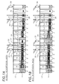
- the magnet array of Figs. 1A and 1B includes a succession of reaction vessels such as cuvettes 12, each containing assay components and magnetizable particles 14 which are initially in a freely distributed state within the respective cuvette 12.
- concentration of solid phase (bound component) of the assay remaining in free suspension in the cuvette at position B is less than that of the first cuvette 12 in position A due to the initial collection of solid phase proximate magnets of the array 16 at position B.
- this effect is more evident.
- the majority of the solid phase 14 has collected proximate respective magnets of the array 16.
- references to "magnets" adjacent a respective position are understood to refer to a pair of adjacent magnets of oppositely oriented polarity, one above the other, proximate the respective cuvette position.
- a band of magnetizable particles 14 forms along the junction of these two magnets, where the magnetic gradient is at a maximum.
- Non-resuspension washes are provided at positions F, G, and M in the illustrative embodiment of Fig. 1A, and at positions F and M in the embodiment of Fig. 1B.
- liquid phase is aspirated from the cuvette 12 via tubes (15, 17, 19 in Fig. 1A and 15, 19 in Fig. 1B) and wash buffer is reintroduced via nozzles (30, 32, 34 in Fig. 1A and 30, 34 in Fig. 1B).
- the nozzles are positioned in front of respective tubes in the view of Figs. 1A and 1B. In particular, the nozzles are angled toward the front of the respective cuvette 12 (out of the page in Figs. 1A and 1B) to avoid disturbing the pellet of solid phase 14 collected at the respective magnets of the array 16.
- the tube 21 at position N of Figs. 1A and 1B is employed to aspirate liquid phase from the respective cuvette 12 prior to the introduction, at position P, of reagent via nozzle 36, the reagent facilitating a subsequent chemiluminescent reaction within a luminometer.
- the reagent dispensing nozzles 36 are angled toward the pellet of solid phase 14 in order to thoroughly disperse it.
- a portion of the liquid phase may remain trapped within the solid phase 14 prior to introduction of the reagent at position P, even after repeated non-resuspension washes, such as at positions F, G, and M in Fig. 1A and positions F and M in Fig. 1B. This trapped liquid phase limits the accuracy of the assay.
- the magnets of the array 16 proximate the cuvettes 12 are disposed at a lower position.
- This provides the solid phase pellet 14 with time to recollect at the lower position prior to the introduction of assay reagent at position P.
- the solid phase 14 will be centrally located in the reaction vessel 12 when the acid is applied at position P.
- such repositioning of the pellet does not necessarily enhance the ability of the non-resuspension washes to rid the solid phase 14 of trapped liquid phase.
- a resuspension wash is not employed, and as such the focused, or localized, solid phase remains proximate respective magnets 16 as the cuvette 12 progresses through the wash block.
- the magnet array of Fig. 1B does employ a resuspension wash.
- Resuspension washing of the solid phase involves the aspiration of the liquid phase containing the unbound components of the assay from the cuvette 12 at position G via the tube 17 while the bound components are held in place by respective magnets in the array 16. This is followed by re-introduction of wash buffer into the cuvette 12 at position H by a dispense nozzle 32 angled at the solid phase pellet 14 collected at the back of the cuvette 12 proximate the magnets 16.
- magnets of the array 16 have been replaced by a soft magnetic insert 20.
- the magnetizable particles are resuspended, exposing more surface area, and freeing liquid phase trapped during initial magnetizable particle collection.
- the solid phase After the solid phase has been resuspended, it is recollected by a subsequent series of magnets in the array 16 at positions I et seq . prior to aspiration of the wash buffer and introduction of the acid reagent at position P.
- Other wash stages in addition to those illustrated, are possible.
- the wash block of Figs. 1A and 1B is provided with a large gap in the magnet array at position H, thus enhancing resuspension wash.
- Prior art magnet arrays employed narrower gaps, resulting in split bands of magnetizable particles due to the attractive forces of array magnets on either side of the narrow gap.
- the present invention avoids the splitting of the solid phase material into bands at opposite sides of the cuvette 12, in part, by providing a focusing of the solid phase 14 into a smaller band or dot 24.
- the gap at the resuspension wash position is filled with an insert 20 made of a soft magnetic material such as low carbon steel.
- the magnets of the array 16 at positions G and I on either side of the resuspension wash position, position H, are trimmed such that the gap in the array of magnets 16 and the insert 20 extend proximate a region of the reaction vessels 12 previously occupied by the solid phase band 14 adjacent to the resuspension wash position.
- the magnetizable particle banding pattern in the reaction vessel at the resuspension wash position, position H remains unchanged in the absence of resuspension wash (Fig. 1A).
- the large soft magnetic insert 20 With resuspension wash (Fig. 1B), the large soft magnetic insert 20 enables the complete resuspension of the solid phase 14 free of influence of magnets at positions G and I.
- the provision of magnets trimmed on a left-hand side at position I downstream of the resuspension wash position, position H further serves to avoid influencing the magnetizable particles during the resuspension wash in Fig. 1B.
- the array 16 magnets at position I, downstream of the resuspension wash position, position H, and the soft magnetic insert 20, is also trimmed on its left-hand side in Fig. 1A. This serves to focus the solid phase 14 downstream of the resuspension wash position, position H.
- the magnetizable particles on the left side of the reaction vessel 12 are no longer directly aligned with magnets 16 at position I. Rather, they migrate toward the right, into the center of the vessel 12.
- the net effect is a conversion of the magnetizable particles from a wide band 14 to a more compact, centrally located band 26.
- the single magnetizable particle band at position H does not split into two bands as in the prior art because the soft magnetic insert 20 acts to short out, or minimize, the magnitude of the field gradient in the resuspension wash position, position H, and because trimming the magnets of the array 16 at positions G and I reduces the reach of the fields, from the same, into the resuspension position H.
- trimmed magnets 27 are provided to further narrow the band of collected magnetizable particles.
- even smaller magnets 28, focusing magnets are employed at position N to focus the magnetizable particles into yet a smaller area, thus providing a smaller target of solid phase 24 at position P for more efficient resuspension upon dispense of reagent.
- Smaller, focusing magnets 28 are not used in a preferred embodiment for the initial collection of the solid phase because, amongst other things, the larger the magnet surface area, the faster the collection of the magnetizable particles.
- all of the magnets in the array 16 along the length of the wash block are provided as focusing magnets 28, though the resuspension wash position, position H, would continue to be provided with a gap such as that provided by the soft magnetic block 20 of Figs. 1A and 1B.
- a gap such as that provided by the soft magnetic block 20 of Figs. 1A and 1B.
- such an embodiment would require more time for each reaction vessel 12 to be proximate the magnets 28 in the array to provide an equivalent degree of capture capability due to the smaller size of the magnets in such an embodiment.
- the reaction vessels 12 containing the suspended solid phase 14 are laterally translated along the magnet array 16 by a linked conveyor belt 40 comprised of a sequence of reaction vessel receptacles 42.
- a sequence of freely rotatable rollers 44 are employed to provide support for the conveyor belt 40.
- At least one such roller 46 is mechanically connected to a motor 48, wherein the motor 48 rotates this roller 46, which in turn causes the conveyor belt 40 and the reaction vessels 12 disposed therein to translate relative to the magnet array 16.
- the rear view of the magnet array in Fig. 3 illustrates a first embodiment of a magnet array 16 support structure 50.
- the magnet array 16 of Fig. 3 is a reverse view of the magnet array 16 of Figs. 1A and 1B.
- the magnets of the array are backed by a conductive material such as high-iron, low-carbon steel to focus the magnetic field toward the reaction vessels 12.
- the support structure 50 which attaches to the magnet backing material, is preferably provided from a magnetically non-reactive material such as aluminum or one of its alloys to avoid unwanted disturbances in the magnetic field established within the reaction vessels.
- the magnets of the array 16 and the backing material are fastened to the support structure 50 in a variety of ways, including via the use of adhesive or mechanical fasteners.
- the support structure 50 is itself suspended by being mechanically attached to a wall of an enclosure (not illustrated), either by adhesive, mechanical fasteners, or some combination thereof.
- the element is segmented into three portions: an initial portion to the right of Fig. 3, a central portion, and a small final portion on the left.
- the latter provides support for the focusing magnets 24.
- the central portion and the final portion are combined, such that the support structure is formed of two portions.
- Fig. 3 also illustrates a rear view of! the soft magnetic insert 20. Disposed in a central location thereof is a cross-section of a mechanical fastener 52 such as a screw employed in securing the insert 20 to a wall of the enclosure.
- the soft magnetic insert is supported by a respective support element such as a stanchion or by an extension of the array magnet support element 50.
- the support element 50 would then be one continuous element, if the final portion and the central portion are continuous, or two elements if the focusing magnets 24 is supported independently.
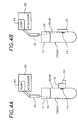
- wash buffer nozzles as employed along the magnet array 16 of the foregoing is illustrated in Figs. 4A and 4B.
- a nozzle 30 such as that used for reintroduction of wash buffer at position F in Figs. 1A or 1B is shown in cross-section in Fig. 4A.
- Solid phase 14 has collected proximate the magnet array 16 (supported by the support element 50) at the rear of the reaction vessel 12.
- the nozzle 30 is oriented with respect to the reaction vessel 12 to provide a stream 60 of wash buffer from a wash buffer reservoir 62 via a pump 64 to a front, interior surface of the reaction vessel 12. This avoids disturbing the solid phase collected at the rear of the vessel 12.
- FIG. 4B the orientation of a nozzle 32 such as that used for resuspension wash at position H in Fig. 1B is illustrated in Fig. 4B.
- a stream 66 of wash buffer from the reservoir 62 via the pump 64 is directed at the solid phase previously collected proximate magnets in the array 16, but now adjacent the soft magnetic insert 20. The solid phase is therefore not retained by magnets, and is easily washed back into suspension by the stream 66 of wash buffer from the nozzle 32.
- the present invention has been described in the context of a chemiluminescent immunoassay, it can be applied to other assay environments in which the separation of bound and unbound components by magnetic separation is required. Further, the exact number of positions in which magnetizable particles are exposed to magnets 16 depends upon the exact nature of the desired separation, the configuration of the magnets 16, the characteristics of the magnetizable particles and the associated bound component, etc.
- Nozzle 32 has been shown in two locations in Figs. 1A and 1B, specifically position H in Fig. 1A and position I in Fig. 1B. While provided as one nozzle with a like reference identifier in both figures, each embodiment of Fig. 1A and 1B could be provided with a nozzle at position G for non-resuspension wash, and another nozzle at position H for use in an embodiment employing resuspension wash. Thus, the same array configuration could be used for assays both employing and not employing resuspension wash.
- reaction vessels 12 are translated along the magnet array 16 by way of a sequence of respective reaction vessel yokes (not illustrated) connected to the respective reaction vessel near the top of the vessel.
- Figs. 4A and 4B The arrangement of elements in Figs. 4A and 4B is a generalized illustration of the relationship between the elements, and is not intended to represent a preferred layout.
- the nozzle 30, 32 in Figs. 4A and 4B can also be located at the same relative position above a respective reaction vessel 12, but angled in opposite directions to properly direct the respective stream 60, 66.
- the pump and reservoir can be provided in a variety of ways, as known to one skilled in the art.
Landscapes
- Health & Medical Sciences (AREA)
- Immunology (AREA)
- Life Sciences & Earth Sciences (AREA)
- Engineering & Computer Science (AREA)
- Molecular Biology (AREA)
- Biomedical Technology (AREA)
- Chemical & Material Sciences (AREA)
- Hematology (AREA)
- Urology & Nephrology (AREA)
- Biotechnology (AREA)
- Microbiology (AREA)
- Cell Biology (AREA)
- Food Science & Technology (AREA)
- Medicinal Chemistry (AREA)
- Physics & Mathematics (AREA)
- Analytical Chemistry (AREA)
- Biochemistry (AREA)
- General Health & Medical Sciences (AREA)
- General Physics & Mathematics (AREA)
- Pathology (AREA)
- Automatic Analysis And Handling Materials Therefor (AREA)
- Apparatus Associated With Microorganisms And Enzymes (AREA)
Claims (9)
- Bloc de lavage dans un ensemble d'aimants permettant une séparation magnétique de composants liés et non liés dans des récipients réactionnels passant devant ledit bloc de lavage dans une instrumentation d'analyse, dans lequel le bloc de lavage comprend :une région de lavage de remise en suspension comportant plusieurs positions de récipient réactionnel lorsque lesdits récipients passent devant ledit ensemble, ledit bloc de lavage au niveau de la région de lavage de remise en suspension comprenant :une position centrale de récipient réactionnel à proximité de laquelle ledit bloc de lavage comporte un élément rapporté magnétique doux dans ledit ensemble d'aimants,une première position de récipient réactionnel disposée avant ladite position centrale de récipient réactionnel, ledit bloc de lavage à ladite première position de récipient réactionnel comportant des aimants découpés et une première partie dudit élément rapporté magnétique doux à proximité de l'un desdits récipients ;
etune seconde position de récipient réactionnel disposée après ladite position centrale de récipient réactionnel, ledit bloc de lavage à ladite seconde position de récipient réactionnel comportant des aimants découpés et une seconde partie dudit élément rapporté magnétique doux à proximité de l'un desdits récipients. - Bloc de lavage selon la revendication 1, qui comprend en outre :une région de séparation initiale comportant plusieurs positions de récipient réactionnel de séparation initiale lorsque lesdits récipients passent devant ledit ensemble, ladite région de séparation initiale étant disposée avant ladite région de lavage de remise en suspension, chacune desdites positions de séparation initiale fournissant des aimants à proximité d'un récipient réactionnel respectif ;et/ou une région de séparation suivante comportant plusieurs positions suivantes de récipient réactionnel de séparation lorsque lesdits récipients passent devant ledit ensemble, ladite région de séparation suivante étant disposée après ladite région de lavage de remise en suspension, chacune desdites positions de séparation suivante fournissant des aimants à proximité d'un récipient respectif ; de préférence au moins une position de ladite pluralité de positions suivantes de récipient réactionnel de séparation comprenant en outre au moins une paire d'aimants de focalisation de taille plus petite que lesdits aimants placés à proximité desdites positions initiales de récipient réactionnel de séparation.
- Ensemble d'aimants destiné à permettre une séparation magnétique de composants liés et non liés dans au moins un récipient réactionnel passant au travers de celui-ci, dans lequel l'ensemble d'aimants comprend :un étage de séparation initiale destiné à séparer ledit composant lié dudit composant non lié dans ledit au moins un récipient réactionnel ;un étage de lavage de remise en suspension à la suite dudit étage de séparation initiale, ledit étage de lavage de remise en suspension permettant sélectivement un lavage de remise en suspension dudit composant lié dans ledit au moins un récipient réactionnel, et ledit étage de lavage de remise en suspension comprenant en outre une position de distribution de tampon de lavage comportant une buse de distribution de tampon de lavage, ledit au moins un récipient réactionnel étant positionné à ladite position de distribution de tampon de lavage afin de recevoir un tampon de lavage depuis ladite buse de distribution de tampon de lavage ; un élément magnétique doux rapporté se trouvant à ladite position de distribution de tampon de lavage ; et/ou une position de récipient réactionnel avant lavage avant ladite position de distribution de tampon de lavage et une position de récipient réactionnel après lavage après celle-ci, ledit élément rapporté magnétique doux chevauchant lesdites positions avant lavage et après lavage et lesdites positions avant lavage et après lavage comportant des aimants respectifs découpés pour loger ledit élément rapporté magnétique doux en chevauchement ; ledit élément rapporté magnétique doux étant formé de préférence d'acier à faible teneur en carbone ;un étage de séparation suivante à la suite dudit étage de lavage de remise en suspension afin de focaliser ledit composant lié à l'intérieur dudit au moins un récipient réactionnel et d'aspirer ledit composant non lié depuis l'intérieur dudit au moins un récipient réactionnel ;
etun étage de mélange de réactif à la suite dudit étage de séparation suivante, ledit étage de mélange de réactif permettant la distribution d'un réactif en vue d'une remise en suspension dudit composant lié dans ledit au moins un récipient réactionnel ;ledit étage de séparation initiale, ledit étage de lavage de remise en suspension, ledit étage de séparation suivante et ledit étage de mélange de réactif comprenant collectivement plusieurs positions de récipient réactionnel disposées de façon consécutive à l'intérieur dudit ensemble d'aimants et ledit étage de lavage de remise en suspension conservant une configuration physique de composant lié dans ledit au moins un récipient réactionnel en l'absence dudit lavage de remise en suspension activé sélectivement. - Ensemble d'aimants selon la revendication 3, dans lequel ledit étage de séparation initiale, ledit étage de lavage de remise en suspension et ledit étage de séparation suivante comprennent chacun au moins une paire d'aimants dudit ensemble d'aimants à proximité de positions respectives parmi lesdites positions de récipient réactionnel.
- Ensemble d'aimants selon la revendication 3 ou la revendication 4, dans lequel ledit étage de séparation suivante comprend en outre au moins une paire d'aimants, à proximité d'une position respective parmi lesdites positions de récipient réactionnel, présentant une taille plus petite que ladite au moins une paire d'aimants dudit étage de séparation initiale afin de permettre une focalisation desdits composants liés à l'intérieur dudit au moins un récipient réactionnel à ladite position respective parmi lesdites positions de récipient réactionnel.
- Ensemble d'aimants selon l'une quelconque des revendications 3 à 5, lequel comprend en outre un étage de lavage de remise en suspension secondaire disposé de façon consécutive avec et entre ledit étage de séparation suivante et ledit étage de mélange de réactif.
- Procédé destiné à séparer des composants d'une analyse, liés à des particules magnétisables, des composants non liés en utilisant un ensemble d'aimants, dans lequel le procédé comprend :la disposition desdits composants d'analyse liés et non liés dans un récipient réactionnel ;le passage dudit récipient réactionnel à proximité d'une première série de paires d'aimants disposées à la suite dans ledit ensemble d'aimants afin d'induire une séparation initiale desdits composants liés par rapport auxdits composants non liés ;le passage dudit récipient réactionnel à proximité d'un étage de lavage de remise en suspension dudit ensemble d'aimants partiellement constitué d'un élément magnétique doux rapporté afin de permettre sélectivement le lavage de remise en suspension desdits composants liés ;
etle passage dudit récipient réactionnel à proximité d'une seconde série de paires d'aimants disposées à la suite dans ledit ensemble d'aimants afin d'induire une séparation suivante desdits composants liés. - Procédé selon la revendication 7, dans lequel ledit passage dudit récipient réactionnel à proximité d'un étage de lavage de remise en suspension comprend en outre :le passage, à la suite, dudit récipient réactionnel par :une première position comportant une première paire d'aimants découpés et une première partie dudit élément rapporté magnétique doux à proximité de celle-ci ;une seconde position comportant une seconde partie dudit élément rapporté magnétique doux à proximité de celle-ci ;
etune troisième position comportant une troisième partie dudit élément rapporté magnétique doux et une seconde paire d'aimants découpés à proximité de celle-ci ;et l'aspiration facultative dudit composant non lié depuis ledit récipient réactionnel à ladite première position ;
etla distribution d'un tampon de lavage dans ledit récipient réactionnel à ladite seconde position. - Procédé selon la revendication 7 ou la revendication 8, dans lequel ledit passage dudit récipient réactionnel à proximité d'une seconde série de paires d'aimants disposées à la suite comprend en outre :le passage dudit récipient réactionnel à proximité d'une seconde série de paires d'aimants dont un sous-ensemble d'au moins une dernière paire d'aimants de ladite seconde série comprend au moins une paire d'aimants de focalisation de plus petite taille relativement aux autres paires d'aimants de ladite seconde série ;et l'aspiration facultative desdits composants non liés à partir dudit récipient réactionnel lorsque ledit récipient réactionnel est à proximité d'une dernière paire de ladite au moins une paire d'aimants de focalisation ;
etle passage dudit récipient réactionnel à proximité d'un étage de mélange de réactif disposé à la suite après ladite seconde série de paires d'aimants disposées à la suite dans ledit ensemble d'aimants, un tampon réactif étant distribué dans ledit récipient réactionnel afin de remettre en suspension lesdits composants liés.
Applications Claiming Priority (2)
| Application Number | Priority Date | Filing Date | Title |
|---|---|---|---|
| US644909 | 1991-01-23 | ||
| US08/644,909 US5888835A (en) | 1996-05-10 | 1996-05-10 | Method and apparatus for wash, resuspension, recollection and localization of magnetizable particles in assays using magnetic separation technology |
Publications (2)
| Publication Number | Publication Date |
|---|---|
| EP0806665A1 EP0806665A1 (fr) | 1997-11-12 |
| EP0806665B1 true EP0806665B1 (fr) | 2000-03-15 |
Family
ID=24586856
Family Applications (1)
| Application Number | Title | Priority Date | Filing Date |
|---|---|---|---|
| EP97303120A Expired - Lifetime EP0806665B1 (fr) | 1996-05-10 | 1997-05-08 | Procédé et appareil de lavage, remise en suspension, reprécipitation et localisation des particules magnétisables selon la technique de séparation magnétique des échantillons |
Country Status (5)
| Country | Link |
|---|---|
| US (1) | US5888835A (fr) |
| EP (1) | EP0806665B1 (fr) |
| JP (1) | JP4208100B2 (fr) |
| CA (1) | CA2199211A1 (fr) |
| DE (1) | DE69701418T2 (fr) |
Cited By (4)
| Publication number | Priority date | Publication date | Assignee | Title |
|---|---|---|---|---|
| USD560816S1 (en) | 2007-02-08 | 2008-01-29 | Biokit, S.A. | Cuvette |
| USD565741S1 (en) | 2007-02-08 | 2008-04-01 | Biokit, S.A. | Mixing tube |
| USD620603S1 (en) | 2007-02-08 | 2010-07-27 | Biokit S.A. | Reagent container pack |
| USD621520S1 (en) | 2007-02-08 | 2010-08-10 | Biokit, S.A. | Cuvette |
Families Citing this family (23)
| Publication number | Priority date | Publication date | Assignee | Title |
|---|---|---|---|---|
| US6143578A (en) * | 1996-05-10 | 2000-11-07 | Bayer Corporation | Method and apparatus for wash, resuspension, recollection and localization of magnetizable particles in assays using magnetic separation technology |
| ES2286750T3 (es) | 1998-05-01 | 2007-12-01 | Gen-Probe Incorporated | Dispositivo para agitar el contenido liquido de un contenedor. |
| JP2001091521A (ja) * | 1999-09-21 | 2001-04-06 | Olympus Optical Co Ltd | 自動分析装置 |
| US6672458B2 (en) * | 2000-05-19 | 2004-01-06 | Becton, Dickinson And Company | System and method for manipulating magnetically responsive particles fluid samples to collect DNA or RNA from a sample |
| DE10136060A1 (de) * | 2001-07-25 | 2003-02-13 | Roche Diagnostics Gmbh | System zur Separation von magnetisch anziehbaren Partikeln |
| WO2003086637A1 (fr) * | 2002-04-12 | 2003-10-23 | Instrumentation Laboratory Company | Sonde d'immunodosage |
| US20040157219A1 (en) * | 2003-02-06 | 2004-08-12 | Jianrong Lou | Chemical treatment of biological samples for nucleic acid extraction and kits therefor |
| CH697124A5 (de) * | 2004-01-08 | 2008-05-15 | Qiagen Instr Ag | Trennen und Reinigen einer Suspension mit magnetischen Mikropartikeln. |
| US20050239091A1 (en) * | 2004-04-23 | 2005-10-27 | Collis Matthew P | Extraction of nucleic acids using small diameter magnetically-responsive particles |
| JP2008500538A (ja) * | 2004-05-24 | 2008-01-10 | バイエル コーポレイション | 磁気粒子再懸濁プローブ・モジュール |
| US8211386B2 (en) * | 2004-06-08 | 2012-07-03 | Biokit, S.A. | Tapered cuvette and method of collecting magnetic particles |
| JP5053089B2 (ja) * | 2004-08-03 | 2012-10-17 | ベクトン・ディキンソン・アンド・カンパニー | 化合物の直接単離および多成分サンプルの分別のための磁性材料の使用 |
| US8728413B2 (en) | 2007-02-08 | 2014-05-20 | Biokit, S.A. | Reagent container pack |
| US7731414B2 (en) * | 2007-02-08 | 2010-06-08 | Instrumentation Laboratory Company | Reagent cartridge mixing tube |
| US7731899B2 (en) | 2007-02-08 | 2010-06-08 | Biokit, S.A. | Apparatus and methods for dispensing sample holders |
| US8795609B2 (en) * | 2007-02-08 | 2014-08-05 | Biokit, S.A. | Magnetic particle washing station |
| CA2692186C (fr) * | 2007-06-29 | 2019-03-12 | Becton, Dickinson And Company | Procede d'extraction et de purification de composants d'echantillons biologiques |
| JP5319672B2 (ja) * | 2008-06-12 | 2013-10-16 | 株式会社日立ハイテクノロジーズ | 磁性粒子を用いる分析装置 |
| EP2752668A3 (fr) | 2010-07-23 | 2014-10-15 | Beckman Coulter, Inc. | Système ou procédé comprenant des unités analytiques |
| JP6610550B2 (ja) * | 2014-09-19 | 2019-11-27 | 日立化成ダイアグノスティックス・システムズ株式会社 | 磁性担体粒子の洗浄方法、磁性担体粒子の洗浄装置、及び磁性担体粒子を用いる免疫学的測定方法 |
| JP6858008B2 (ja) | 2016-11-30 | 2021-04-14 | シスメックス株式会社 | 粒子分散装置及び粒子分散方法 |
| CN110082549B (zh) * | 2018-01-25 | 2023-10-10 | 深圳市新产业生物医学工程股份有限公司 | 清洗装置及化学发光检测仪 |
| CN110883039B (zh) * | 2018-09-11 | 2021-06-04 | 深圳市新产业生物医学工程股份有限公司 | 吸附机构、清洗装置、化学发光检测仪及清洗方法 |
Family Cites Families (29)
| Publication number | Priority date | Publication date | Assignee | Title |
|---|---|---|---|---|
| US4265855A (en) * | 1978-11-03 | 1981-05-05 | Electro-Nucleonics, Inc. | System for performing immunochemical and other analyses involving phase separation |
| US4698302A (en) * | 1983-05-12 | 1987-10-06 | Advanced Magnetics, Inc. | Enzymatic reactions using magnetic particles |
| US4628037A (en) * | 1983-05-12 | 1986-12-09 | Advanced Magnetics, Inc. | Binding assays employing magnetic particles |
| GB8401368D0 (en) * | 1984-01-19 | 1984-02-22 | Amersham Int Plc | Assay method |
| JP2510152B2 (ja) * | 1985-11-19 | 1996-06-26 | オリンパス光学工業株式会社 | 自動分析装置 |
| US4661408A (en) * | 1986-03-18 | 1987-04-28 | E.I. Du Pont De Nemours And Company | Coated chromium dioxide particles |
| CH669266A5 (fr) * | 1986-10-14 | 1989-02-28 | Serono Diagnostics Ltd | Appareil d'analyse automatique pour le dosage d'anticorps ou d'antigenes dans un liquide biologique. |
| US5091206A (en) * | 1987-10-26 | 1992-02-25 | Baxter Diagnostics Inc. | Process for producing magnetically responsive polymer particles and application thereof |
| US5395688A (en) * | 1987-10-26 | 1995-03-07 | Baxter Diagnostics Inc. | Magnetically responsive fluorescent polymer particles |
| GB8800419D0 (en) * | 1988-01-08 | 1988-02-10 | Amersham Int Plc | Method for measuring free fraction of ligands in biological fluids |
| US5256532A (en) * | 1988-05-02 | 1993-10-26 | Zynaxis Technologies, Inc. | Methods, reagents and test kits for determination of subpopulations of biological entities |
| US5147529A (en) * | 1988-08-10 | 1992-09-15 | E. I. Du Pont De Nemours And Company | Method for automatically processing magnetic solid phase reagents |
| US5104808A (en) * | 1988-08-26 | 1992-04-14 | Laska Paul F | Method and apparatus for effecting a plurality of assays on a plurality of samples in an automatic analytical device |
| US5108933A (en) * | 1988-09-16 | 1992-04-28 | Immunicon Corporation | Manipulation of colloids for facilitating magnetic separations |
| DE3840462A1 (de) * | 1988-12-01 | 1990-06-07 | Berthold Lab Prof R | Verfahren und vorrichtung zur messung der chemilumineszenz |
| IL94212A0 (en) * | 1989-07-24 | 1991-01-31 | Tri Tech Partners And Triton B | Automated analytical apparatus and method |
| US5183638A (en) * | 1989-12-04 | 1993-02-02 | Kabushiki Kaisha Nittec | Automatic immunity analysis apparatus with magnetic particle separation |
| US5200084A (en) * | 1990-09-26 | 1993-04-06 | Immunicon Corporation | Apparatus and methods for magnetic separation |
| JP2548626B2 (ja) * | 1990-11-21 | 1996-10-30 | 三井製薬工業株式会社 | 免疫自動分析装置 |
| US5128103A (en) * | 1990-12-14 | 1992-07-07 | E. I. Du Pont De Nemours And Company | Apparatus for automatically processing magnetic solid phase reagents |
| US5491068A (en) * | 1991-02-14 | 1996-02-13 | Vicam, L.P. | Assay method for detecting the presence of bacteria |
| CA2384519C (fr) * | 1991-03-04 | 2006-08-15 | Bayer Corporation | Analyseur automatise |
| US5186827A (en) * | 1991-03-25 | 1993-02-16 | Immunicon Corporation | Apparatus for magnetic separation featuring external magnetic means |
| US5466574A (en) * | 1991-03-25 | 1995-11-14 | Immunivest Corporation | Apparatus and methods for magnetic separation featuring external magnetic means |
| US5232665A (en) * | 1991-07-26 | 1993-08-03 | E. I. Du Pont De Nemours And Company | Multi-linear automatic apparatus for processing immunoassays |
| EP0589636B1 (fr) * | 1992-09-24 | 2000-08-02 | Amersham Pharmacia Biotech UK Limited | Méthode et appratus pour la séparation magnétique |
| ATE195081T1 (de) * | 1992-09-24 | 2000-08-15 | Amersham Pharm Biotech Uk Ltd | Verfahren und vorrichtung zur magnetischen abscheidung |
| US5374531A (en) * | 1993-03-22 | 1994-12-20 | Zynaxis, Inc. | Immunoassay for determination of cells |
| DE4429155A1 (de) * | 1994-08-17 | 1996-02-22 | Hans Schiesl | Meßanordnung und Verfahren zur Durchführung luminometrischer Reihenanalysen sowie Mehrfachküvette zur Aufnahme von Flüssigkeitsproben hierfür |
-
1996
- 1996-05-10 US US08/644,909 patent/US5888835A/en not_active Expired - Lifetime
-
1997
- 1997-03-05 CA CA002199211A patent/CA2199211A1/fr not_active Abandoned
- 1997-05-08 EP EP97303120A patent/EP0806665B1/fr not_active Expired - Lifetime
- 1997-05-08 DE DE69701418T patent/DE69701418T2/de not_active Expired - Lifetime
- 1997-05-12 JP JP12118597A patent/JP4208100B2/ja not_active Expired - Lifetime
Cited By (4)
| Publication number | Priority date | Publication date | Assignee | Title |
|---|---|---|---|---|
| USD560816S1 (en) | 2007-02-08 | 2008-01-29 | Biokit, S.A. | Cuvette |
| USD565741S1 (en) | 2007-02-08 | 2008-04-01 | Biokit, S.A. | Mixing tube |
| USD620603S1 (en) | 2007-02-08 | 2010-07-27 | Biokit S.A. | Reagent container pack |
| USD621520S1 (en) | 2007-02-08 | 2010-08-10 | Biokit, S.A. | Cuvette |
Also Published As
| Publication number | Publication date |
|---|---|
| DE69701418D1 (de) | 2000-04-20 |
| EP0806665A1 (fr) | 1997-11-12 |
| DE69701418T2 (de) | 2000-07-06 |
| JP4208100B2 (ja) | 2009-01-14 |
| MX9701411A (es) | 1997-11-29 |
| JPH1096732A (ja) | 1998-04-14 |
| CA2199211A1 (fr) | 1997-11-10 |
| US5888835A (en) | 1999-03-30 |
Similar Documents
| Publication | Publication Date | Title |
|---|---|---|
| EP0806665B1 (fr) | Procédé et appareil de lavage, remise en suspension, reprécipitation et localisation des particules magnétisables selon la technique de séparation magnétique des échantillons | |
| US6143578A (en) | Method and apparatus for wash, resuspension, recollection and localization of magnetizable particles in assays using magnetic separation technology | |
| JP4642227B2 (ja) | 混合物からの成分の連続的な磁気的分離方法 | |
| EP0358948B1 (fr) | Méthode pour effectuer automatiquement des réactifs magnétiques en phase solide | |
| US7517457B2 (en) | Method of mixing magnetic particles | |
| JP6385956B2 (ja) | 生体試料の液滴から標的物質を分離するための装置および方法 | |
| US20030127396A1 (en) | Apparatus and method for processing magnetic particles | |
| US20020141913A1 (en) | Apparatus and methods for magnetic separation | |
| US8371743B2 (en) | Method for suspending or re-suspending particles in a solution and apparatus adapted thereto | |
| US20080257825A1 (en) | Method for treating magnetic particles and biological analysis device using magnets | |
| JP4651894B2 (ja) | 磁性粒子を利用した混合/分離装置及び方法 | |
| CA2366543A1 (fr) | Separateur electromagnetique multiphase destine a purifier des cellules, des produits chimiques et des structures proteiques | |
| Rampini et al. | Micromagnet arrays for on-chip focusing, switching, and separation of superparamagnetic beads and single cells | |
| JP2005028201A (ja) | 磁気分離器及びそれを用いた分析装置 | |
| MXPA97001411A (en) | Method and apparatus for washing, resuspension, collection and localization of magnetizing particles in tests using magnet separation technology |
Legal Events
| Date | Code | Title | Description |
|---|---|---|---|
| PUAI | Public reference made under article 153(3) epc to a published international application that has entered the european phase |
Free format text: ORIGINAL CODE: 0009012 |
|
| AK | Designated contracting states |
Kind code of ref document: A1 Designated state(s): CH DE FR GB IT LI |
|
| RIN1 | Information on inventor provided before grant (corrected) |
Inventor name: KIRCHICK, HOWARD J. Inventor name: MALEK, MICHAEL L. Inventor name: GARYANTES, TINA K. Inventor name: BUSHNELL, STEVEN E. |
|
| 17P | Request for examination filed |
Effective date: 19980420 |
|
| 17Q | First examination report despatched |
Effective date: 19981201 |
|
| GRAG | Despatch of communication of intention to grant |
Free format text: ORIGINAL CODE: EPIDOS AGRA |
|
| GRAG | Despatch of communication of intention to grant |
Free format text: ORIGINAL CODE: EPIDOS AGRA |
|
| GRAH | Despatch of communication of intention to grant a patent |
Free format text: ORIGINAL CODE: EPIDOS IGRA |
|
| GRAH | Despatch of communication of intention to grant a patent |
Free format text: ORIGINAL CODE: EPIDOS IGRA |
|
| RAP1 | Party data changed (applicant data changed or rights of an application transferred) |
Owner name: BAYER CORPORATION |
|
| GRAA | (expected) grant |
Free format text: ORIGINAL CODE: 0009210 |
|
| AK | Designated contracting states |
Kind code of ref document: B1 Designated state(s): CH DE FR GB IT LI |
|
| REG | Reference to a national code |
Ref country code: CH Ref legal event code: EP |
|
| ITF | It: translation for a ep patent filed | ||
| REF | Corresponds to: |
Ref document number: 69701418 Country of ref document: DE Date of ref document: 20000420 |
|
| REG | Reference to a national code |
Ref country code: CH Ref legal event code: NV Representative=s name: KIRKER & CIE SA |
|
| ET | Fr: translation filed | ||
| PLBE | No opposition filed within time limit |
Free format text: ORIGINAL CODE: 0009261 |
|
| STAA | Information on the status of an ep patent application or granted ep patent |
Free format text: STATUS: NO OPPOSITION FILED WITHIN TIME LIMIT |
|
| 26N | No opposition filed | ||
| REG | Reference to a national code |
Ref country code: GB Ref legal event code: IF02 |
|
| REG | Reference to a national code |
Ref country code: CH Ref legal event code: PUE Owner name: BAYER HEALTHCARE LLC Free format text: BAYER CORPORATION#100 BAYER ROAD#PITTSBURGH, PA 15205 (US) -TRANSFER TO- BAYER HEALTHCARE LLC#555 WHITE PLAINS ROAD#TARRYTOWN, NY 10591 (US) Ref country code: CH Ref legal event code: PUE Owner name: SIEMENS HEALTHCARE DIAGNOSTICS INC. Free format text: BAYER HEALTHCARE LLC#555 WHITE PLAINS ROAD#TARRYTOWN, NY 10591 (US) -TRANSFER TO- SIEMENS HEALTHCARE DIAGNOSTICS INC.#511 BENEDICT AVENUE#TARRYTOWN, NY 10591 (US) Ref country code: CH Ref legal event code: PCOW Free format text: BAYER CORPORATION;100 BAYER ROAD;PITTSBURGH, PA 15205 (US) Ref country code: CH Ref legal event code: NV Representative=s name: SIEMENS SCHWEIZ AG |
|
| PGFP | Annual fee paid to national office [announced via postgrant information from national office to epo] |
Ref country code: IT Payment date: 20100526 Year of fee payment: 14 |
|
| REG | Reference to a national code |
Ref country code: GB Ref legal event code: 732E Free format text: REGISTERED BETWEEN 20101104 AND 20101110 |
|
| REG | Reference to a national code |
Ref country code: FR Ref legal event code: TP |
|
| PG25 | Lapsed in a contracting state [announced via postgrant information from national office to epo] |
Ref country code: IT Free format text: LAPSE BECAUSE OF NON-PAYMENT OF DUE FEES Effective date: 20110508 |
|
| REG | Reference to a national code |
Ref country code: FR Ref legal event code: PLFP Year of fee payment: 20 |
|
| PGFP | Annual fee paid to national office [announced via postgrant information from national office to epo] |
Ref country code: GB Payment date: 20160512 Year of fee payment: 20 |
|
| PGFP | Annual fee paid to national office [announced via postgrant information from national office to epo] |
Ref country code: FR Payment date: 20160512 Year of fee payment: 20 |
|
| PGFP | Annual fee paid to national office [announced via postgrant information from national office to epo] |
Ref country code: CH Payment date: 20160802 Year of fee payment: 20 Ref country code: DE Payment date: 20160720 Year of fee payment: 20 |
|
| REG | Reference to a national code |
Ref country code: DE Ref legal event code: R071 Ref document number: 69701418 Country of ref document: DE |
|
| REG | Reference to a national code |
Ref country code: CH Ref legal event code: PL |
|
| REG | Reference to a national code |
Ref country code: GB Ref legal event code: PE20 Expiry date: 20170507 |
|
| PG25 | Lapsed in a contracting state [announced via postgrant information from national office to epo] |
Ref country code: GB Free format text: LAPSE BECAUSE OF EXPIRATION OF PROTECTION Effective date: 20170507 |