EP0806688A1 - Zentrierelement, Verfahren für die Verbindung einer Anzahl von Fasern an eine Mehrkernfaser und so hergestellte Koppel-/Verteilervorrichtung - Google Patents
Zentrierelement, Verfahren für die Verbindung einer Anzahl von Fasern an eine Mehrkernfaser und so hergestellte Koppel-/Verteilervorrichtung Download PDFInfo
- Publication number
- EP0806688A1 EP0806688A1 EP97401037A EP97401037A EP0806688A1 EP 0806688 A1 EP0806688 A1 EP 0806688A1 EP 97401037 A EP97401037 A EP 97401037A EP 97401037 A EP97401037 A EP 97401037A EP 0806688 A1 EP0806688 A1 EP 0806688A1
- Authority
- EP
- European Patent Office
- Prior art keywords
- fibers
- ferrules
- centering component
- centering
- fiber
- Prior art date
- Legal status (The legal status is an assumption and is not a legal conclusion. Google has not performed a legal analysis and makes no representation as to the accuracy of the status listed.)
- Granted
Links
- 239000000835 fiber Substances 0.000 title claims abstract description 84
- 238000000034 method Methods 0.000 title claims description 17
- 238000003466 welding Methods 0.000 claims abstract description 12
- 230000003287 optical effect Effects 0.000 claims description 13
- 239000013307 optical fiber Substances 0.000 claims description 8
- 230000004927 fusion Effects 0.000 claims description 2
- 239000008188 pellet Substances 0.000 claims description 2
- 230000001681 protective effect Effects 0.000 claims 1
- CSCPPACGZOOCGX-UHFFFAOYSA-N Acetone Chemical compound CC(C)=O CSCPPACGZOOCGX-UHFFFAOYSA-N 0.000 abstract description 4
- KRHYYFGTRYWZRS-UHFFFAOYSA-N Fluorane Chemical compound F KRHYYFGTRYWZRS-UHFFFAOYSA-N 0.000 abstract description 4
- 238000010891 electric arc Methods 0.000 abstract description 2
- 239000007788 liquid Substances 0.000 abstract description 2
- 239000002131 composite material Substances 0.000 abstract 1
- 239000000126 substance Substances 0.000 description 3
- 238000002844 melting Methods 0.000 description 2
- 230000008018 melting Effects 0.000 description 2
- OKTJSMMVPCPJKN-UHFFFAOYSA-N Carbon Chemical compound [C] OKTJSMMVPCPJKN-UHFFFAOYSA-N 0.000 description 1
- 239000011248 coating agent Substances 0.000 description 1
- 238000000576 coating method Methods 0.000 description 1
- 230000008878 coupling Effects 0.000 description 1
- 238000010168 coupling process Methods 0.000 description 1
- 238000005859 coupling reaction Methods 0.000 description 1
- 229910002804 graphite Inorganic materials 0.000 description 1
- 239000010439 graphite Substances 0.000 description 1
- 238000010438 heat treatment Methods 0.000 description 1
- 238000009434 installation Methods 0.000 description 1
- 239000011159 matrix material Substances 0.000 description 1
- 239000000203 mixture Substances 0.000 description 1
- 238000003825 pressing Methods 0.000 description 1
- 238000005476 soldering Methods 0.000 description 1
Images


Classifications
-
- G—PHYSICS
- G02—OPTICS
- G02B—OPTICAL ELEMENTS, SYSTEMS OR APPARATUS
- G02B6/00—Light guides; Structural details of arrangements comprising light guides and other optical elements, e.g. couplings
- G02B6/24—Coupling light guides
- G02B6/26—Optical coupling means
- G02B6/264—Optical coupling means with optical elements between opposed fibre ends which perform a function other than beam splitting
-
- G—PHYSICS
- G02—OPTICS
- G02B—OPTICAL ELEMENTS, SYSTEMS OR APPARATUS
- G02B6/00—Light guides; Structural details of arrangements comprising light guides and other optical elements, e.g. couplings
- G02B6/24—Coupling light guides
- G02B6/255—Splicing of light guides, e.g. by fusion or bonding
- G02B6/2551—Splicing of light guides, e.g. by fusion or bonding using thermal methods, e.g. fusion welding by arc discharge, laser beam, plasma torch
-
- G—PHYSICS
- G02—OPTICS
- G02B—OPTICAL ELEMENTS, SYSTEMS OR APPARATUS
- G02B6/00—Light guides; Structural details of arrangements comprising light guides and other optical elements, e.g. couplings
- G02B6/24—Coupling light guides
- G02B6/36—Mechanical coupling means
- G02B6/38—Mechanical coupling means having fibre to fibre mating means
- G02B6/3807—Dismountable connectors, i.e. comprising plugs
- G02B6/3873—Connectors using guide surfaces for aligning ferrule ends, e.g. tubes, sleeves, V-grooves, rods, pins, balls
- G02B6/3885—Multicore or multichannel optical connectors, i.e. one single ferrule containing more than one fibre, e.g. ribbon type
Definitions
- the present invention relates to a centering component intended to be used for the connection of a plurality of fibers to a multicore fiber.
- It also relates to a method for connecting a plurality of elementary fibers to a multicore fiber.
- Multicore optical fibers are optical guides comprising in a same linear matrix a plurality of parallel guide cores.
- the centering component which serves to correctly position the elementary fibers relative to each other remains in place on said fibers at the end of the step where said fibers are fixed on one another.
- An object of the invention is to provide a connection of a multicore fiber to a plurality of elementary fibers which is very low cost.
- the invention provides a centering component intended to be used for the connection of a plurality of elementary fibers and of a multi-core fiber, characterized in that it comprises two half-ferrules and means for holding said said half-ferrules one on the other in a separable way.
- It also proposes a method for the connection of a multi-core optical fiber to a plurality of optical fibers in which these are gathered and are introduced into a centering component in which said fibers necessarily fit according to a geometry corresponding to that of the axes of the multi-core fiber, characterized in that the centering component is of the aforementioned type and in that a welded splice is made between the multi-core fiber and the plurality of fibers gathered in the centering component, then the element is released optic thus obtained half ferrules of the centering component.
- the centering component is reusable after a connection.
- the invention also relates to spark gaps without a centering component obtained by this process.
- connection to multicore fibers connections of p elementary fibers to a fiber with n hearts, or of several fibers p hearts to a fiber n hearts, with p less than n ( splitting of a fiber with four hearts into two fibers two hearts for example).
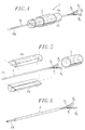
- the four elementary fibers F1 to F4 are placed in a centering component 1 using the technique which was more particularly described in French patent application FR 94 03467.
- the four monomode fibers F1 to F4 - whose optical sheath initially has an external diameter of 125 ⁇ m - are subjected to a chemical attack with hydrofluoric acid, so as to reduce their diameter of optical sheath to a diameter of 44 ⁇ m.
- the end shape of the fibers can be conical or cylindrical.
- the fibers F1 to F4 are combined.
- the surface tension of a liquid which is for example acetone, is used for this purpose.
- the fibers thus gathered are ready to be introduced into the centering component 1.
- the latter is positioned on a vertical stem, this arrangement facilitating the introduction of the fibers F1 to F4 assembled.
- the internal geometry of the centering component 1 is such that the fibers F1 to F4 are necessarily inscribed in an arrangement where their hearts C1 to C4 extend according to a geometry which coincides with that of the hearts C'1 to C'4 of the multicore FM fiber - in this case a square.
- the centering component 1 consists of two half-ferrules 2a and 2b and an elastic ring 3 which is a split skirt intended to hold said half-ferrules 2a and 2b one on the other.
- the half-ferrules 2a and 2b end with half-pellets 4a and 4b intended, when said half-ferrules are attached to each other, to define a calibrated patch whose centering hole extends the orifice of the ferrule defined by the two half-ferrules 2a and 2b.
- This centering hole is less than a micrometer in accuracy.
- the assembly thus formed is transferred to one of the cradles 5 of a welding machine, the other cradle 6 of which receives the FM multi-core fiber (FIG. 3).
- the centering component 1 and the multicore FM fiber are held on the cradles 5 and 6 by pressing means, shown diagrammatically by arrows in FIG. 3.
- the cradles 5 and 6 are mounted on piezoelectric means which make it possible to adjust their relative position horizontally and vertically.
- This relative position is adjusted so that the axis of the multi-core FM fiber coincides with the axis of the hole for centering the calibrated pad of the centering component 1.
- the welding machine also comprises means making it possible to adjust the relative angular orientation ⁇ of the two cradles 5 and 6 around this common axis, so as to allow the alignment of the hearts C'1 to C'4 of the FM multi-core fiber. and hearts C1 to C4 of elementary fibers F1 to F4.
- These means include for example a manual or automatic rotator acting on the position of the FM multicore fiber.
- a weld is made between the optical sheaths of said multi-core FM fiber and said elementary fibers F1 to F4, for example by electric arc welding, as shown by the electrodes 7 in FIG. 3, or also by welding with a CO 2 laser, with a torch, or even with a graphite susceptor oven.
- the FM multi-core fiber is optionally, prior to its installation on the cradle 6, subjected to an appropriate chemical attack, intended to make its diameter close to that of the fibers F1 to F4, in order to make the fusion of the whole homogeneous.
- an optical spark gap consisting of a multi-core fiber extended by several elementary fibers, with continuity of the hearts C'1 to C'4 of the multi-core fiber FM and of the hearts C1 to C4 of the elementary fibers F1 to F4, (that is to say absence of Fresnel reflection), and absence of coupling mixture between the hearts.
- the various parameters of the melting are managed on a case-by-case basis, for example by computer means controlling the electrodes 7.
- the optical spark gap obtained at the end of the welding operation has been illustrated in FIG. 4.
- the splicing zone has been referenced by E in this figure.
- the centering component constituted by the two half-ferrules 2a and 2b and the elastic ring 3 can then be reused for another welding operation.
- the final component thus obtained is an optical coupler / spark gap which can be connected in line by soldering or any other conventional connection means, with all the performance required in attenuation (less than 0.5 dB), in crosstalk (less than 52 dB / core) and in reflection (less than 60 dB).
- This component which does not have a ferrule, is compact and can be handled and stored in the same way as a conventional optical fiber.
Landscapes
- Physics & Mathematics (AREA)
- General Physics & Mathematics (AREA)
- Optics & Photonics (AREA)
- Engineering & Computer Science (AREA)
- Plasma & Fusion (AREA)
- Mechanical Coupling Of Light Guides (AREA)
Applications Claiming Priority (2)
| Application Number | Priority Date | Filing Date | Title |
|---|---|---|---|
| FR9605791 | 1996-05-09 | ||
| FR9605791A FR2748575B1 (fr) | 1996-05-09 | 1996-05-09 | Composant de centrage, procede pour le raccordement d'une pluralite de fibres a une fibre multicoeur et coupleur/eclateur ainsi obtenu |
Publications (2)
| Publication Number | Publication Date |
|---|---|
| EP0806688A1 true EP0806688A1 (de) | 1997-11-12 |
| EP0806688B1 EP0806688B1 (de) | 2003-03-26 |
Family
ID=9491978
Family Applications (1)
| Application Number | Title | Priority Date | Filing Date |
|---|---|---|---|
| EP97401037A Expired - Lifetime EP0806688B1 (de) | 1996-05-09 | 1997-05-07 | Zentrierelement, Verfahren für die Verbindung einer Anzahl von Fasern an eine Mehrkernfaser und so hergestellte Koppel-/Verteilervorrichtung |
Country Status (3)
| Country | Link |
|---|---|
| EP (1) | EP0806688B1 (de) |
| DE (1) | DE69720095T2 (de) |
| FR (1) | FR2748575B1 (de) |
Cited By (2)
| Publication number | Priority date | Publication date | Assignee | Title |
|---|---|---|---|---|
| US6539151B2 (en) | 2000-08-21 | 2003-03-25 | Corning, Incorporated | Method for making separable multiple core optical fibers, the resulting fiber structures, and uses thereof |
| CN115903139A (zh) * | 2023-01-16 | 2023-04-04 | 浙江康阔光智能科技有限公司 | 保偏光纤熔接机的端面定位方法及光纤端面定位装置 |
Citations (9)
| Publication number | Priority date | Publication date | Assignee | Title |
|---|---|---|---|---|
| US4101198A (en) * | 1976-06-21 | 1978-07-18 | Hewlett-Packard Company | Fiber optic connector with split ferrule assembly |
| JPS55164802A (en) * | 1979-06-12 | 1980-12-22 | Nippon Telegr & Teleph Corp <Ntt> | Manufacture of branching circuit for multicore optical fiber |
| JPS5752013A (en) * | 1980-09-12 | 1982-03-27 | Nippon Telegr & Teleph Corp <Ntt> | Branching circuit for multicore optical fiber |
| JPS63259602A (ja) * | 1987-04-17 | 1988-10-26 | Nippon Telegr & Teleph Corp <Ntt> | 光フアイバ融着接続機 |
| EP0575009A1 (de) * | 1992-06-19 | 1993-12-22 | SIRTI S.p.A. | Verfahren zum Schmelzformen eines optischen Signalabschwächers |
| EP0576266A2 (de) * | 1992-06-25 | 1993-12-29 | Hughes Aircraft Company | Faseroptische Laserspleissvorrichtung |
| WO1994025885A1 (de) * | 1993-04-27 | 1994-11-10 | Niebuhr Optoelektronik Gmbh | Faserhalter |
| EP0674197A1 (de) * | 1994-03-24 | 1995-09-27 | France Telecom | Verbindungsvorrichtung für eine Mehrkernfaser und Verfahren zu ihrer Herstellung |
| EP0674198A1 (de) * | 1994-03-24 | 1995-09-27 | France Telecom | Bauteil zum Anschluss an eine Mehrkernfaser und Herstellungsprozess |
Family Cites Families (2)
| Publication number | Priority date | Publication date | Assignee | Title |
|---|---|---|---|---|
| FR2524654B1 (fr) * | 1982-03-30 | 1985-10-04 | Socapex | Dispositif de raccordement de fibres optiques et procede le mettant en oeuvre |
| JPH05307116A (ja) * | 1992-05-01 | 1993-11-19 | Sumitomo Electric Ind Ltd | 光ファイバクランプ |
-
1996
- 1996-05-09 FR FR9605791A patent/FR2748575B1/fr not_active Expired - Fee Related
-
1997
- 1997-05-07 DE DE1997620095 patent/DE69720095T2/de not_active Expired - Fee Related
- 1997-05-07 EP EP97401037A patent/EP0806688B1/de not_active Expired - Lifetime
Patent Citations (9)
| Publication number | Priority date | Publication date | Assignee | Title |
|---|---|---|---|---|
| US4101198A (en) * | 1976-06-21 | 1978-07-18 | Hewlett-Packard Company | Fiber optic connector with split ferrule assembly |
| JPS55164802A (en) * | 1979-06-12 | 1980-12-22 | Nippon Telegr & Teleph Corp <Ntt> | Manufacture of branching circuit for multicore optical fiber |
| JPS5752013A (en) * | 1980-09-12 | 1982-03-27 | Nippon Telegr & Teleph Corp <Ntt> | Branching circuit for multicore optical fiber |
| JPS63259602A (ja) * | 1987-04-17 | 1988-10-26 | Nippon Telegr & Teleph Corp <Ntt> | 光フアイバ融着接続機 |
| EP0575009A1 (de) * | 1992-06-19 | 1993-12-22 | SIRTI S.p.A. | Verfahren zum Schmelzformen eines optischen Signalabschwächers |
| EP0576266A2 (de) * | 1992-06-25 | 1993-12-29 | Hughes Aircraft Company | Faseroptische Laserspleissvorrichtung |
| WO1994025885A1 (de) * | 1993-04-27 | 1994-11-10 | Niebuhr Optoelektronik Gmbh | Faserhalter |
| EP0674197A1 (de) * | 1994-03-24 | 1995-09-27 | France Telecom | Verbindungsvorrichtung für eine Mehrkernfaser und Verfahren zu ihrer Herstellung |
| EP0674198A1 (de) * | 1994-03-24 | 1995-09-27 | France Telecom | Bauteil zum Anschluss an eine Mehrkernfaser und Herstellungsprozess |
Non-Patent Citations (3)
| Title |
|---|
| PATENT ABSTRACTS OF JAPAN vol. 005, no. 042 (P - 053) 20 March 1981 (1981-03-20) * |
| PATENT ABSTRACTS OF JAPAN vol. 006, no. 125 (P - 127) 10 July 1982 (1982-07-10) * |
| PATENT ABSTRACTS OF JAPAN vol. 013, no. 073 (P - 830) 20 February 1989 (1989-02-20) * |
Cited By (3)
| Publication number | Priority date | Publication date | Assignee | Title |
|---|---|---|---|---|
| US6539151B2 (en) | 2000-08-21 | 2003-03-25 | Corning, Incorporated | Method for making separable multiple core optical fibers, the resulting fiber structures, and uses thereof |
| CN115903139A (zh) * | 2023-01-16 | 2023-04-04 | 浙江康阔光智能科技有限公司 | 保偏光纤熔接机的端面定位方法及光纤端面定位装置 |
| CN115903139B (zh) * | 2023-01-16 | 2023-09-22 | 浙江康阔光智能科技有限公司 | 保偏光纤熔接机的端面定位方法及光纤端面定位装置 |
Also Published As
| Publication number | Publication date |
|---|---|
| EP0806688B1 (de) | 2003-03-26 |
| FR2748575B1 (fr) | 1998-07-31 |
| DE69720095D1 (de) | 2003-04-30 |
| DE69720095T2 (de) | 2003-10-30 |
| FR2748575A1 (fr) | 1997-11-14 |
Similar Documents
| Publication | Publication Date | Title |
|---|---|---|
| CA1131952A (fr) | Connecteur pour liaison a fibre optique | |
| CA1105749A (fr) | Dispositif de raccordement global en bout de deux groupes de sept fibres optiques | |
| EP0011011B1 (de) | Endhülle eines Verbindungsstücks für eine optische Einzelfaser und mit derartiger Endhülle versehenes Verbindungsstück | |
| EP0011561B1 (de) | Verfahren zum Anbringen einer optischen Faser in einer Verbindungszwinge | |
| CA1123243A (fr) | Connecteur pour fibres optiques et dispositif de montage des fibres sur des embouts directement utilisables sur connecteur | |
| EP0051519B1 (de) | Zwinge für einen Verbinder für optische Fasern und Verbinder mit einer solchen Zwinge | |
| WO1983001123A1 (fr) | Cellule de centrage pour raccordement de fibres optiques | |
| EP0581671A1 (de) | Verfahren zur Ankopplung einer Glasfaser an einen optischen Baustein auf einem gemeinsamen Substrat | |
| FR2466028A1 (fr) | Connecteurs pour fibres optiques | |
| EP0806688B1 (de) | Zentrierelement, Verfahren für die Verbindung einer Anzahl von Fasern an eine Mehrkernfaser und so hergestellte Koppel-/Verteilervorrichtung | |
| EP0036369B1 (de) | Verfahren und Vorrichtung zum Verbinden faseroptischer Kabel auf dem Arbeitsplatz | |
| JP7716200B2 (ja) | マルチコアファイバ及びマルチコアファイバの製造方法 | |
| EP0165841B1 (de) | Verfahren zur Verbindung von optischen Fasern und Vorrichtung die aus diesem Verfahren erreichbar ist | |
| EP0718648A1 (de) | Herstellungsverfahren für optischen Mehrfachfaserverteiler und damit hergestellter optischer Verteiler | |
| KR101096495B1 (ko) | 접속기 홀더장치 및 이를 포함하는 융착 접속기 | |
| CA2063208C (fr) | Procede de raccordement de deux cables a fibres optiques par epissurage | |
| CA1193125A (fr) | Connecteur optique monofibre | |
| FR2580822A1 (fr) | Douille de raccordement pour le couplage d'un faisceau laser et d'un guide d'ondes optique | |
| FR2695733A1 (fr) | Procédés de préparation du raccordement par épissurage d'un dispositif d'optique intégrée à au moins un câble optique. | |
| FR2676287A1 (fr) | Dispositif et procede d'epanouissement de fibres optiques au-dela d'une extremite gainee de cable unitube. | |
| EP0406797A1 (de) | Steckstift für optische Faser, sein Montageverfahren und Verbindungsmethode von zwei optischen Fasern mit Hilfe dieser Steckstifte | |
| FR2747800A1 (fr) | Eclateur pour fibre multicoeur | |
| EP2428827A1 (de) | Schutzvorrichtung einer Spleißung, und Installationsverfahren für eine solche Vorrichtung | |
| FR2500936A1 (fr) | Dispositif de connexion de deux elements de cable a fibres optiques | |
| FR2476856A1 (fr) | Dispositif de connexion de fibres optiques et procede pour sa mise en oeuvre |
Legal Events
| Date | Code | Title | Description |
|---|---|---|---|
| PUAI | Public reference made under article 153(3) epc to a published international application that has entered the european phase |
Free format text: ORIGINAL CODE: 0009012 |
|
| AK | Designated contracting states |
Kind code of ref document: A1 Designated state(s): DE GB |
|
| 17P | Request for examination filed |
Effective date: 19980409 |
|
| 17Q | First examination report despatched |
Effective date: 20010517 |
|
| GRAH | Despatch of communication of intention to grant a patent |
Free format text: ORIGINAL CODE: EPIDOS IGRA |
|
| GRAH | Despatch of communication of intention to grant a patent |
Free format text: ORIGINAL CODE: EPIDOS IGRA |
|
| GRAA | (expected) grant |
Free format text: ORIGINAL CODE: 0009210 |
|
| AK | Designated contracting states |
Designated state(s): DE GB |
|
| REG | Reference to a national code |
Ref country code: GB Ref legal event code: FG4D Free format text: NOT ENGLISH |
|
| GBT | Gb: translation of ep patent filed (gb section 77(6)(a)/1977) |
Effective date: 20030326 |
|
| REF | Corresponds to: |
Ref document number: 69720095 Country of ref document: DE Date of ref document: 20030430 Kind code of ref document: P |
|
| PLBE | No opposition filed within time limit |
Free format text: ORIGINAL CODE: 0009261 |
|
| STAA | Information on the status of an ep patent application or granted ep patent |
Free format text: STATUS: NO OPPOSITION FILED WITHIN TIME LIMIT |
|
| 26N | No opposition filed |
Effective date: 20031230 |
|
| PGFP | Annual fee paid to national office [announced via postgrant information from national office to epo] |
Ref country code: DE Payment date: 20080514 Year of fee payment: 12 |
|
| PGFP | Annual fee paid to national office [announced via postgrant information from national office to epo] |
Ref country code: GB Payment date: 20080424 Year of fee payment: 12 |
|
| GBPC | Gb: european patent ceased through non-payment of renewal fee |
Effective date: 20090507 |
|
| PG25 | Lapsed in a contracting state [announced via postgrant information from national office to epo] |
Ref country code: GB Free format text: LAPSE BECAUSE OF NON-PAYMENT OF DUE FEES Effective date: 20090507 |
|
| PG25 | Lapsed in a contracting state [announced via postgrant information from national office to epo] |
Ref country code: DE Free format text: LAPSE BECAUSE OF NON-PAYMENT OF DUE FEES Effective date: 20091201 |