EP0806715A1 - Procédé pour la régulation d'un appareil de desserte de rayonnages commandé par ordinateur - Google Patents
Procédé pour la régulation d'un appareil de desserte de rayonnages commandé par ordinateur Download PDFInfo
- Publication number
- EP0806715A1 EP0806715A1 EP95118823A EP95118823A EP0806715A1 EP 0806715 A1 EP0806715 A1 EP 0806715A1 EP 95118823 A EP95118823 A EP 95118823A EP 95118823 A EP95118823 A EP 95118823A EP 0806715 A1 EP0806715 A1 EP 0806715A1
- Authority
- EP
- European Patent Office
- Prior art keywords
- storage
- control circuit
- drive
- current
- retrieval
- Prior art date
- Legal status (The legal status is an assumption and is not a legal conclusion. Google has not performed a legal analysis and makes no representation as to the accuracy of the status listed.)
- Granted
Links
Images
Classifications
-
- G—PHYSICS
- G05—CONTROLLING; REGULATING
- G05B—CONTROL OR REGULATING SYSTEMS IN GENERAL; FUNCTIONAL ELEMENTS OF SUCH SYSTEMS; MONITORING OR TESTING ARRANGEMENTS FOR SUCH SYSTEMS OR ELEMENTS
- G05B19/00—Program-control systems
- G05B19/02—Program-control systems electric
- G05B19/18—Numerical control [NC], i.e. automatically operating machines, in particular machine tools, e.g. in a manufacturing environment, so as to execute positioning, movement or co-ordinated operations by means of program data in numerical form
- G05B19/19—Numerical control [NC], i.e. automatically operating machines, in particular machine tools, e.g. in a manufacturing environment, so as to execute positioning, movement or co-ordinated operations by means of program data in numerical form characterised by positioning or contouring control systems, e.g. to control position from one programmed point to another or to control movement along a programmed continuous path
-
- B—PERFORMING OPERATIONS; TRANSPORTING
- B66—HOISTING; LIFTING; HAULING
- B66F—HOISTING, LIFTING, HAULING OR PUSHING, NOT OTHERWISE PROVIDED FOR, e.g. DEVICES WHICH APPLY A LIFTING OR PUSHING FORCE DIRECTLY TO THE SURFACE OF A LOAD
- B66F9/00—Devices for lifting or lowering bulky or heavy goods for loading or unloading purposes
- B66F9/06—Devices for lifting or lowering bulky or heavy goods for loading or unloading purposes movable, with their loads, on wheels or the like, e.g. fork-lift trucks
- B66F9/07—Floor-to-roof stacking devices, e.g. "stacker cranes", "retrievers"
-
- Y—GENERAL TAGGING OF NEW TECHNOLOGICAL DEVELOPMENTS; GENERAL TAGGING OF CROSS-SECTIONAL TECHNOLOGIES SPANNING OVER SEVERAL SECTIONS OF THE IPC; TECHNICAL SUBJECTS COVERED BY FORMER USPC CROSS-REFERENCE ART COLLECTIONS [XRACs] AND DIGESTS
- Y10—TECHNICAL SUBJECTS COVERED BY FORMER USPC
- Y10S—TECHNICAL SUBJECTS COVERED BY FORMER USPC CROSS-REFERENCE ART COLLECTIONS [XRACs] AND DIGESTS
- Y10S706/00—Data processing: artificial intelligence
- Y10S706/902—Application using ai with detail of the ai system
- Y10S706/903—Control
- Y10S706/905—Vehicle or aerospace
Definitions
- the invention relates to a method for regulating a computer-controlled, on a traveling frame a mast with a lifting platform arranged thereon and provided with a load-carrying means, comprising a current control circuit, a drive control circuit including a speed control circuit and a position control circuit.
- Such storage and retrieval machines or conveyors fulfill the transport task, for example in logistic systems which comprise a high-bay warehouse as an essential component, in a fully automatic or manual manner, i.e. the transfer of a loading unit from the storage location to the storage location and from there to the removal location.
- the spectrum of goods to be stored extends from small packages weighing only a few kilograms to coils weighing around 40 tons, for example metal strips wound into bundles.
- the storage heights and, depending on this, the height of the storage and retrieval machines are in a range from approx. 6 m to 45 m.
- the respective storage dimensions are opened up by the freely movable or guided rack operator device by its travel drive in the horizontal X direction, by the lifting drive of the lifting drive which can be moved vertically on the vertical mast for the lifting platform in the vertical Y direction and by the load suspension device drive in the Z direction .
- the tall, slim masts, on which the already mentioned, sometimes quite large loads are moved up and down, are flexible, extremely vibratory systems with variable dynamic properties, which e.g. can be stimulated by motor acceleration and deceleration, road impacts, brake application and controller influence.
- Drive controllers for lifting and travel drives with interfaces to different variable-speed electrical drives used for this purpose are servomotors with servo drive amplifiers, DC motors with converters and three-phase asynchronous motors with frequency converters.
- the interfaces mentioned delimit the controller hierarchically downwards; the upward interface is specified by the storage and retrieval machine control, which notifies the controller of the target points of the travel movements and for Safety functions, limit switches, coordination tasks, error diagnosis, communication to the warehouse management computer, etc. is responsible.
- a position measuring system which transmits the current position of the storage and retrieval machine to the controller via absolute or indirect measurement.
- the so-called “3-point position controller” and the “cascade controller”, which are based on three different, cascade-shaped controller circuits, are the state-of-the-art controller concepts: the current control loop as the inner circle, the speed control loop and the position control loop as the outer circle. Strictly speaking, of these controller concepts, the "3-point position controller” is not a position controller, but rather a path-dependent speed control, with the result that a multi-stage deceleration process with time losses occurs. Since there is no continuous comparison between the actual position and the setpoint, the cumulative position differences can only be compensated for at the end of the deceleration process during slow speed travel at a reduced speed.
- the multi-stage positioning thus brings with it multiple changes in speed and thus also changes in acceleration and deceleration, which favors vibrations of the mast of the storage and retrieval machine.
- the "cascade controller” is characterized by the fact that a continuous comparison of the actual position and setpoint takes place and positional differences are actively compensated for by adjusting the speed setpoint. Due to this concept, there are fewer starting points for vibration excitation.
- a passive method is therefore used in both controller concepts by limiting the change in acceleration over time or the associated jerk by specifying a suitable command variable. Accordingly, there is a transition from a sudden change in acceleration to a linearly increasing or to a sinusoidal rounding. This vibration minimization is disadvantageous however, that due to the rounding while maintaining the maximum acceleration value, the average acceleration decreases, which is inevitably associated with wasted time.
- the invention is therefore based on the object of creating a generic control method of the type mentioned at the outset, which makes it possible to decisively expand the intervention options and narrow technical limits which are limited in the known controller concepts.
- This object is achieved in that the instantaneous dynamic behavior of the storage and retrieval machine is calculated from an existing data base of a status and fault observer controller module using existing measurement and control variables that contain information about the device dynamics and on the basis of coefficient maps on the basis of a basic setting of the sizes of the storage and retrieval machine and an iterative estimation algorithm from a controller module that performs automatic self-learning coefficient identification.
- a self-learning adaptive state controller which takes into account an active vibration damping which takes into account the current dynamic state of the storage and retrieval unit, which results in a considerably broader spectrum of optimization options.
- the control procedure integrates further information containing information about the current dynamic behavior of the storage and retrieval machine, e.g. the mast deflection and relative speed of the mast tip and the position deviation in the case of positive toothed belt drives.
- This additional information or device-dynamic variables for describing the device dynamics are not obtained by measurement technology, but rather are calculated from existing data with the aid of a mathematical model of the state and fault observer controller module, for example the mast deflection and relative speed from the existing current signal.
- the control method according to the invention does not have constant coefficients, but rather coefficient characteristic maps. This takes into account that in practice the coefficients depend on, for example, the current position of the lifting platform, the size of the payload and other influencing variables, all of which are covered by the characteristic diagrams. So that these do not have to be time-consuming to determine in a demanding process, the controller module carries out an automatic self-learning coefficient identification by determining the characteristic fields on the basis of a basic setting with the aid of the mathematical model of the storage and retrieval machine and an iterative estimation algorithm.
- the learning mode of the controller module takes place in the form that a test run is carried out automatically and an additional current test signal is applied as a reference variable in the constant travel phase. From the target / actual comparison, the estimation algorithm calculates the parameters of the transfer function, which in turn lead to the coefficient maps using the mathematical model.
- a preferred embodiment of the invention provides that the current wheel pressure of the storage and retrieval machine is calculated by the status and fault observer controller module and the drive torque or the motor current is limited to the currently possible maximum in the drive or speed control loop. This allows the effects of the dynamics of the storage and retrieval machine on the wheel pressures between the wheels or drive wheels and the rail or the foundation to be taken into account.
- the driven wheels transmit lower frictional forces, which can lead to slippage in the acceleration or deceleration phases and thus to the wheels spinning or locking.
- the active vibration damping already counteracts this influence significantly, the torque monitoring enables the elimination of this influence in the drive control circuit due to a corresponding controller module.
- the current wheel pressure and the drive torque or the are calculated continuously Motor current currently adjusted accordingly.
- the advantage of the torque monitoring controller module is consequently that the instantaneous maximum acceleration or braking torque is always transmitted in accordance with the dynamic behavior of the storage and retrieval unit.
- the torque or motor current regulator loop is superimposed by a continuous comparison of the drive speed and the absolute speed of the storage and retrieval machine, including an absolute displacement measuring system.
- differences caused by slip cause the controller to correct the motor current.
- the energy consumption of the storage and retrieval machine is regulated depending on the current load.
- the invention further provides that the positioning accuracy of the storage and retrieval unit is regulated differently, adapted to the different transport units or stored goods.
- the respective positioning tolerance can be freely selected depending on the respective transport unit. This makes it possible to take into account the wide range of goods to be stored in terms of weight, dimensions and load carriers.
- the different transport units require different position tolerances for the safe transfer from the storage and retrieval machine into the storage compartment of the high-bay warehouse, whereby the positioning controller module ensures that the positioning accuracy is not higher than absolutely necessary in order to keep the seasons as short as possible.
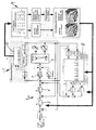
- the controller 1 comprises a reference variable generator 3, a cascade controller 4 with a position controller 5 and a speed controller 6, as well as one Current controllers 7. These are linked via appropriate control loops both to the storage and retrieval unit 2 and to a status and fault observer controller module 8, which uses a mathematical model to describe the data from existing data the additional information required for the device dynamics.
- This is not based on constant coefficients, but rather on coefficient maps, which are determined by a controller module 9 which carries out an automatic self-learning coefficient identification on the basis of a basic setting of the sizes of the storage and retrieval unit 2 and a module 10 for an iterative estimation algorithm.
- the controller 1 combines the advantages of active vibration damping to eliminate vibrations and shorten the decay time, the position control means that the target point is approached as quickly as possible, optimal control access and less drag error, anti-slip control and - since there is no vibration excitation - higher Acceleration values.
- the control parameters can be optimized taking into account different loads, lifting heights and geometries, a design-related dynamic behavior, different drives and types of power transmission and different static and dynamic deformations.
- freely selectable and, if necessary, combinable operating strategies can be carried out.
Landscapes
- Engineering & Computer Science (AREA)
- Transportation (AREA)
- Structural Engineering (AREA)
- Civil Engineering (AREA)
- Life Sciences & Earth Sciences (AREA)
- Geology (AREA)
- Mechanical Engineering (AREA)
- Manufacturing & Machinery (AREA)
- Human Computer Interaction (AREA)
- Physics & Mathematics (AREA)
- General Physics & Mathematics (AREA)
- Automation & Control Theory (AREA)
- Warehouses Or Storage Devices (AREA)
- Control Of Position Or Direction (AREA)
- Control And Safety Of Cranes (AREA)
- Feedback Control In General (AREA)
- Control Of Conveyors (AREA)
Priority Applications (6)
| Application Number | Priority Date | Filing Date | Title |
|---|---|---|---|
| DE59505399T DE59505399D1 (de) | 1995-11-30 | 1995-11-30 | Verfahren zum Regeln eines rechnergesteuerten Regalbediengerätes |
| EP95118823A EP0806715B1 (fr) | 1995-11-30 | 1995-11-30 | Procédé pour la régulation d'un appareil de desserte de rayonnages commandé par ordinateur |
| AT95118823T ATE177850T1 (de) | 1995-11-30 | 1995-11-30 | Verfahren zum regeln eines rechnergesteuerten regalbediengerätes |
| KR1019980704082A KR19990071803A (ko) | 1995-11-30 | 1996-12-02 | 컴퓨터 제어식 운반기계의 구동을 제어하는 방법 |
| PCT/EP1996/005343 WO1997019889A1 (fr) | 1995-11-30 | 1996-12-02 | Procede pour regler le dispositif d'entrainement d'un appareil de transport commande par ordinateur |
| US09/077,535 US6226558B1 (en) | 1995-11-30 | 1996-12-02 | Method of controlling the drive of a computer-controlled conveyor device |
Applications Claiming Priority (1)
| Application Number | Priority Date | Filing Date | Title |
|---|---|---|---|
| EP95118823A EP0806715B1 (fr) | 1995-11-30 | 1995-11-30 | Procédé pour la régulation d'un appareil de desserte de rayonnages commandé par ordinateur |
Publications (2)
| Publication Number | Publication Date |
|---|---|
| EP0806715A1 true EP0806715A1 (fr) | 1997-11-12 |
| EP0806715B1 EP0806715B1 (fr) | 1999-03-17 |
Family
ID=8219846
Family Applications (1)
| Application Number | Title | Priority Date | Filing Date |
|---|---|---|---|
| EP95118823A Expired - Lifetime EP0806715B1 (fr) | 1995-11-30 | 1995-11-30 | Procédé pour la régulation d'un appareil de desserte de rayonnages commandé par ordinateur |
Country Status (6)
| Country | Link |
|---|---|
| US (1) | US6226558B1 (fr) |
| EP (1) | EP0806715B1 (fr) |
| KR (1) | KR19990071803A (fr) |
| AT (1) | ATE177850T1 (fr) |
| DE (1) | DE59505399D1 (fr) |
| WO (1) | WO1997019889A1 (fr) |
Cited By (2)
| Publication number | Priority date | Publication date | Assignee | Title |
|---|---|---|---|---|
| WO2006082168A1 (fr) * | 2005-02-02 | 2006-08-10 | Dematic Gmbh & Co. Kg | Appareil de commande pour un entrepot a rayonnages, en particulier un gerbeur pour un entrepot a rayonnages eleves, et procede pour diriger l'appareil de commande |
| AT501509A1 (de) * | 2005-03-07 | 2006-09-15 | Tgw Transportgeraete Gmbh | Verfahren und positionsregelungseinrichtung zur steuerung des betriebes einer lasttragvorrichtung |
Families Citing this family (16)
| Publication number | Priority date | Publication date | Assignee | Title |
|---|---|---|---|---|
| DE102004048519A1 (de) * | 2004-08-23 | 2006-03-02 | Sandt Logistik Gmbh | Antriebsregelung für ein Regalbediengerät |
| WO2008006928A1 (fr) * | 2006-07-12 | 2008-01-17 | Rocla Oyj | Procédé et dispositif d'amortissement de vibrations dans une structure de mât |
| US8025664B2 (en) | 2006-11-03 | 2011-09-27 | Innovative Spine, Llc | System and method for providing surgical access to a spine |
| JP2008225533A (ja) * | 2007-03-08 | 2008-09-25 | Fanuc Ltd | サーボ制御装置 |
| DE102009004641B4 (de) * | 2009-01-09 | 2020-12-10 | Viastore Systems Gmbh | Logistikeinrichtung und Verfahren zum Betreiben einer Logistikeinrichtung |
| DE102009047036A1 (de) * | 2009-11-24 | 2011-05-26 | Dematic Gmbh | Verfahren zum energiesparenden Betreiben eines Logistiksystems |
| US9244443B2 (en) * | 2010-10-15 | 2016-01-26 | Yoshimasa Kobayashi | Recovery method for logistics system |
| DE102011001112A1 (de) * | 2011-03-04 | 2012-09-06 | Schneider Electric Automation Gmbh | Verfahren und Steuerungseinrichtung zur schwingungsarmen Bewegung eines bewegbaren Kranelementes eines Kransystems |
| US9403667B2 (en) | 2011-03-18 | 2016-08-02 | The Raymond Corporation | Dynamic vibration control systems and methods for industrial lift trucks |
| US8731785B2 (en) | 2011-03-18 | 2014-05-20 | The Raymond Corporation | Dynamic stability control systems and methods for industrial lift trucks |
| US8763990B2 (en) | 2012-03-20 | 2014-07-01 | The Raymond Corporation | Turn stability systems and methods for lift trucks |
| US9302893B2 (en) | 2013-02-07 | 2016-04-05 | The Raymond Corporation | Vibration control systems and methods for industrial lift trucks |
| US9002557B2 (en) | 2013-03-14 | 2015-04-07 | The Raymond Corporation | Systems and methods for maintaining an industrial lift truck within defined bounds |
| AT514152B1 (de) * | 2013-04-08 | 2017-09-15 | Dr Ing Berger Benjamin | Verfahren zum Steuern eines Regalbediengeräts |
| US10071894B2 (en) | 2015-08-03 | 2018-09-11 | The Raymond Corporation | Oscillation damping for a material handling vehicle |
| JP6893792B2 (ja) * | 2017-01-27 | 2021-06-23 | 芝浦機械株式会社 | 工作機械および振動抑制方法 |
Citations (3)
| Publication number | Priority date | Publication date | Assignee | Title |
|---|---|---|---|---|
| DE3803626A1 (de) * | 1988-02-06 | 1989-08-17 | Dambach Ind Anlagen | Regalfoerderzeug und hochregalanlage hierfuer |
| EP0423351A1 (fr) * | 1989-02-23 | 1991-04-24 | Fanuc Ltd. | Procede de commande a mode ajustable |
| US5239248A (en) * | 1991-01-23 | 1993-08-24 | Seiko Instruments Inc. | Servo control system |
Family Cites Families (13)
| Publication number | Priority date | Publication date | Assignee | Title |
|---|---|---|---|---|
| US3638575A (en) * | 1969-07-03 | 1972-02-01 | Palmer Shile Co | Analog control system |
| US4103795A (en) * | 1974-12-19 | 1978-08-01 | Automatic Container Loading Limited | Lifting and loading device |
| US4258825A (en) * | 1978-05-18 | 1981-03-31 | Collins Pat L | Powered manlift cart |
| DE3335402A1 (de) | 1983-09-29 | 1985-04-11 | Siemens AG, 1000 Berlin und 8000 München | Anordnung zum daempfen von schwingungen einer an einem seil eines krans oder anderen hebezeuges haengenden last |
| JPH0756608B2 (ja) * | 1986-03-24 | 1995-06-14 | キヤノン株式会社 | 位置決め制御装置 |
| DE3721184A1 (de) | 1987-06-26 | 1989-01-05 | Siemens Ag | Verfahren zum identifizieren von uebertragungsstrecken, insbesondere von regelstrecken |
| GB2252295B (en) * | 1991-01-31 | 1994-08-03 | James Daniel Davidson | Offshore crane control system |
| CA2061379C (fr) * | 1991-08-22 | 1995-11-14 | William T. Stewart | Convoyeur a palette reglable |
| US5403142A (en) * | 1991-08-22 | 1995-04-04 | Stewart-Glapat Corporation | Pallet handling adjustable conveyor |
| US5792483A (en) * | 1993-04-05 | 1998-08-11 | Vickers, Inc. | Injection molding machine with an electric drive |
| JPH07187318A (ja) * | 1993-12-28 | 1995-07-25 | Komatsu Forklift Co Ltd | スタッカクレーンの走行制御装置 |
| JP3246642B2 (ja) * | 1994-05-16 | 2002-01-15 | 特種製紙株式会社 | 段積みしたシート状包装体の自動ピッキング方法及び装置 |
| DE19519368A1 (de) | 1995-05-26 | 1996-11-28 | Bilfinger Berger Bau | Verfahren zur Bestimmung der Position einer Last |
-
1995
- 1995-11-30 AT AT95118823T patent/ATE177850T1/de not_active IP Right Cessation
- 1995-11-30 DE DE59505399T patent/DE59505399D1/de not_active Expired - Fee Related
- 1995-11-30 EP EP95118823A patent/EP0806715B1/fr not_active Expired - Lifetime
-
1996
- 1996-12-02 WO PCT/EP1996/005343 patent/WO1997019889A1/fr not_active Ceased
- 1996-12-02 US US09/077,535 patent/US6226558B1/en not_active Expired - Fee Related
- 1996-12-02 KR KR1019980704082A patent/KR19990071803A/ko not_active Abandoned
Patent Citations (4)
| Publication number | Priority date | Publication date | Assignee | Title |
|---|---|---|---|---|
| DE3803626A1 (de) * | 1988-02-06 | 1989-08-17 | Dambach Ind Anlagen | Regalfoerderzeug und hochregalanlage hierfuer |
| DE3803626C2 (fr) | 1988-02-06 | 1990-02-15 | Dambach-Industrieanlagen Gmbh, 7560 Gaggenau, De | |
| EP0423351A1 (fr) * | 1989-02-23 | 1991-04-24 | Fanuc Ltd. | Procede de commande a mode ajustable |
| US5239248A (en) * | 1991-01-23 | 1993-08-24 | Seiko Instruments Inc. | Servo control system |
Non-Patent Citations (1)
| Title |
|---|
| HEISS M.: "KENNFELDER IN DER REGELUNGSTECHNIK INPUT-OUTPUT MAPS FOR AUTOMATIC CONTROL", AUTOMATISIERUNGSTECHNIK - AT, vol. 43, no. 8, 1 August 1995 (1995-08-01), pages 363 - 367, XP000523262 * |
Cited By (4)
| Publication number | Priority date | Publication date | Assignee | Title |
|---|---|---|---|---|
| WO2006082168A1 (fr) * | 2005-02-02 | 2006-08-10 | Dematic Gmbh & Co. Kg | Appareil de commande pour un entrepot a rayonnages, en particulier un gerbeur pour un entrepot a rayonnages eleves, et procede pour diriger l'appareil de commande |
| AT501509A1 (de) * | 2005-03-07 | 2006-09-15 | Tgw Transportgeraete Gmbh | Verfahren und positionsregelungseinrichtung zur steuerung des betriebes einer lasttragvorrichtung |
| AT501509B1 (de) * | 2005-03-07 | 2007-02-15 | Tgw Transportgeraete Gmbh | Verfahren und positionsregelungseinrichtung zur steuerung des betriebes einer lasttragvorrichtung |
| US8190288B2 (en) | 2005-03-07 | 2012-05-29 | Tgw Mechanics Gmbh | Method and position regulating device for controlling the operation of a load bearing apparatus, based on two dimensions |
Also Published As
| Publication number | Publication date |
|---|---|
| US6226558B1 (en) | 2001-05-01 |
| KR19990071803A (ko) | 1999-09-27 |
| DE59505399D1 (de) | 1999-04-22 |
| EP0806715B1 (fr) | 1999-03-17 |
| WO1997019889A1 (fr) | 1997-06-05 |
| ATE177850T1 (de) | 1999-04-15 |
Similar Documents
| Publication | Publication Date | Title |
|---|---|---|
| EP0806715B1 (fr) | Procédé pour la régulation d'un appareil de desserte de rayonnages commandé par ordinateur | |
| DE68921534T2 (de) | Elektrisch angetriebene aktive Fahrzeugaufhängung. | |
| EP3115331B1 (fr) | Dispositif de machine inclinant a partir de charge d'entrainement en forme d'impulsions vers des oscillations et procede de fonctionnement d'un tel dispositif | |
| EP2614027B1 (fr) | Procédé de commande d'une machine d'entraînement d'un système d'ascenseur | |
| DE60208952T2 (de) | Krane und Verfahren zum Steuern des Kranes | |
| EP2607292A1 (fr) | Système de transport de marchandises agencées sur des moyens d'aide | |
| DE19907989B4 (de) | Verfahren zur Bahnregelung von Kranen und Vorrichtung zum bahngenauen Verfahren einer Last | |
| AT501509A1 (de) | Verfahren und positionsregelungseinrichtung zur steuerung des betriebes einer lasttragvorrichtung | |
| AT520008B1 (de) | Verfahren zum Dämpfen von Drehschwingungen eines Lastaufnahmeelements einer Hebeeinrichtung | |
| EP3653562A1 (fr) | Procédé et régulateur d'oscillation permettant de réguler les oscillations d'un système technique oscillant | |
| DE112010005324T5 (de) | Steuervorrichtung für einen Fahrstuhl | |
| WO2003040018A1 (fr) | Dispositif elevateur pour un moyen de suspension de charge d'un systeme en hauteur destine a manipuler des unites de stockage | |
| EP3652104A1 (fr) | Dispositif de commande pour un engin de levage et procédé pour le faire fonctionner | |
| DE102007024817A1 (de) | Flurförderzeug mit einem Hubgerüst und einem Stellglied zur Kompensation von Schwingungen | |
| EP3293141A1 (fr) | Procede de fonctionnement d'une grue, en particulier une grue pour conteneurs | |
| EP3006389B1 (fr) | Transstockeur et procede de fonctionnement d'un transstockeur | |
| EP4190739B1 (fr) | Procédé de régulation du mouvement d'une charge dans un espace de travail d'un dispositif de transport de charge | |
| WO2024156497A1 (fr) | Procédé et dispositif d'actionnement d'une grue à flèche orientable, et grue à flèche orientable | |
| DE19918449C2 (de) | Lasthebesystem zur Feinpositionierung und aktiven Schwingungsdämpfung | |
| EP2014600A1 (fr) | Dispositif de compensation | |
| EP1843967B1 (fr) | Appareil de commande pour un entrepot a rayonnages, en particulier un gerbeur pour un entrepot a rayonnages eleves, et procede pour diriger l'appareil de commande | |
| DE202023002939U1 (de) | Vorrichtung zum Betreiben eines Auslegerdrehkrans sowie Auslegerdrehkran | |
| WO2024047193A1 (fr) | Procédé de commande du mouvement d'un axe d'entraînement d'une unité d'entraînement | |
| WO2004016540A1 (fr) | Procede de commande du fonctionnement d'un treuil roulant | |
| EP4174013A1 (fr) | Procédé de déplacement d'une charge à l'aide d'une grue |
Legal Events
| Date | Code | Title | Description |
|---|---|---|---|
| PUAI | Public reference made under article 153(3) epc to a published international application that has entered the european phase |
Free format text: ORIGINAL CODE: 0009012 |
|
| 17P | Request for examination filed |
Effective date: 19951212 |
|
| AK | Designated contracting states |
Kind code of ref document: A1 Designated state(s): AT BE CH DE FR GB LI LU NL SE |
|
| GRAG | Despatch of communication of intention to grant |
Free format text: ORIGINAL CODE: EPIDOS AGRA |
|
| GRAG | Despatch of communication of intention to grant |
Free format text: ORIGINAL CODE: EPIDOS AGRA |
|
| GRAG | Despatch of communication of intention to grant |
Free format text: ORIGINAL CODE: EPIDOS AGRA |
|
| GRAH | Despatch of communication of intention to grant a patent |
Free format text: ORIGINAL CODE: EPIDOS IGRA |
|
| GRAH | Despatch of communication of intention to grant a patent |
Free format text: ORIGINAL CODE: EPIDOS IGRA |
|
| GRAA | (expected) grant |
Free format text: ORIGINAL CODE: 0009210 |
|
| AK | Designated contracting states |
Kind code of ref document: B1 Designated state(s): AT BE CH DE FR GB LI LU NL SE |
|
| REF | Corresponds to: |
Ref document number: 177850 Country of ref document: AT Date of ref document: 19990415 Kind code of ref document: T |
|
| REG | Reference to a national code |
Ref country code: CH Ref legal event code: EP |
|
| REF | Corresponds to: |
Ref document number: 59505399 Country of ref document: DE Date of ref document: 19990422 |
|
| ET | Fr: translation filed | ||
| GBT | Gb: translation of ep patent filed (gb section 77(6)(a)/1977) |
Effective date: 19990420 |
|
| REG | Reference to a national code |
Ref country code: CH Ref legal event code: NV Representative=s name: ULRICH BALLMER, BRIGITTE BALLMER PATENTANWAELTE |
|
| PLBE | No opposition filed within time limit |
Free format text: ORIGINAL CODE: 0009261 |
|
| STAA | Information on the status of an ep patent application or granted ep patent |
Free format text: STATUS: NO OPPOSITION FILED WITHIN TIME LIMIT |
|
| 26N | No opposition filed | ||
| REG | Reference to a national code |
Ref country code: GB Ref legal event code: IF02 |
|
| PGFP | Annual fee paid to national office [announced via postgrant information from national office to epo] |
Ref country code: GB Payment date: 20031029 Year of fee payment: 9 |
|
| PGFP | Annual fee paid to national office [announced via postgrant information from national office to epo] |
Ref country code: NL Payment date: 20031030 Year of fee payment: 9 Ref country code: CH Payment date: 20031030 Year of fee payment: 9 |
|
| PGFP | Annual fee paid to national office [announced via postgrant information from national office to epo] |
Ref country code: LU Payment date: 20031031 Year of fee payment: 9 |
|
| PGFP | Annual fee paid to national office [announced via postgrant information from national office to epo] |
Ref country code: SE Payment date: 20031103 Year of fee payment: 9 Ref country code: DE Payment date: 20031103 Year of fee payment: 9 |
|
| PGFP | Annual fee paid to national office [announced via postgrant information from national office to epo] |
Ref country code: AT Payment date: 20031105 Year of fee payment: 9 |
|
| PGFP | Annual fee paid to national office [announced via postgrant information from national office to epo] |
Ref country code: FR Payment date: 20031107 Year of fee payment: 9 |
|
| PGFP | Annual fee paid to national office [announced via postgrant information from national office to epo] |
Ref country code: BE Payment date: 20031209 Year of fee payment: 9 |
|
| PG25 | Lapsed in a contracting state [announced via postgrant information from national office to epo] |
Ref country code: LU Free format text: LAPSE BECAUSE OF NON-PAYMENT OF DUE FEES Effective date: 20041130 Ref country code: LI Free format text: LAPSE BECAUSE OF NON-PAYMENT OF DUE FEES Effective date: 20041130 Ref country code: GB Free format text: LAPSE BECAUSE OF NON-PAYMENT OF DUE FEES Effective date: 20041130 Ref country code: CH Free format text: LAPSE BECAUSE OF NON-PAYMENT OF DUE FEES Effective date: 20041130 Ref country code: BE Free format text: LAPSE BECAUSE OF NON-PAYMENT OF DUE FEES Effective date: 20041130 Ref country code: AT Free format text: LAPSE BECAUSE OF NON-PAYMENT OF DUE FEES Effective date: 20041130 |
|
| PG25 | Lapsed in a contracting state [announced via postgrant information from national office to epo] |
Ref country code: SE Free format text: LAPSE BECAUSE OF NON-PAYMENT OF DUE FEES Effective date: 20041201 |
|
| BERE | Be: lapsed |
Owner name: *SIEMAG TRANSPLAN G.M.B.H. Effective date: 20041130 |
|
| PG25 | Lapsed in a contracting state [announced via postgrant information from national office to epo] |
Ref country code: NL Free format text: LAPSE BECAUSE OF NON-PAYMENT OF DUE FEES Effective date: 20050601 Ref country code: DE Free format text: LAPSE BECAUSE OF NON-PAYMENT OF DUE FEES Effective date: 20050601 |
|
| REG | Reference to a national code |
Ref country code: CH Ref legal event code: PL |
|
| GBPC | Gb: european patent ceased through non-payment of renewal fee |
Effective date: 20041130 |
|
| PG25 | Lapsed in a contracting state [announced via postgrant information from national office to epo] |
Ref country code: FR Free format text: LAPSE BECAUSE OF NON-PAYMENT OF DUE FEES Effective date: 20050729 |
|
| NLV4 | Nl: lapsed or anulled due to non-payment of the annual fee |
Effective date: 20050601 |
|
| EUG | Se: european patent has lapsed | ||
| REG | Reference to a national code |
Ref country code: FR Ref legal event code: ST |
|
| BERE | Be: lapsed |
Owner name: *SIEMAG TRANSPLAN G.M.B.H. Effective date: 20041130 |