EP0806781A1 - Circuit pour l'alimentation protégée d'une charge électrique - Google Patents
Circuit pour l'alimentation protégée d'une charge électrique Download PDFInfo
- Publication number
- EP0806781A1 EP0806781A1 EP97400951A EP97400951A EP0806781A1 EP 0806781 A1 EP0806781 A1 EP 0806781A1 EP 97400951 A EP97400951 A EP 97400951A EP 97400951 A EP97400951 A EP 97400951A EP 0806781 A1 EP0806781 A1 EP 0806781A1
- Authority
- EP
- European Patent Office
- Prior art keywords
- circuit
- electronic switch
- load
- switch
- contactor
- Prior art date
- Legal status (The legal status is an assumption and is not a legal conclusion. Google has not performed a legal analysis and makes no representation as to the accuracy of the status listed.)
- Granted
Links
- 238000011144 upstream manufacturing Methods 0.000 claims description 8
- 230000002457 bidirectional effect Effects 0.000 claims description 2
- 238000001514 detection method Methods 0.000 description 3
- 238000003466 welding Methods 0.000 description 2
- 239000004020 conductor Substances 0.000 description 1
- 238000010586 diagram Methods 0.000 description 1
- 238000010891 electric arc Methods 0.000 description 1
- 238000013021 overheating Methods 0.000 description 1
- 239000004065 semiconductor Substances 0.000 description 1
- 230000003068 static effect Effects 0.000 description 1
Images
Classifications
-
- H—ELECTRICITY
- H01—ELECTRIC ELEMENTS
- H01H—ELECTRIC SWITCHES; RELAYS; SELECTORS; EMERGENCY PROTECTIVE DEVICES
- H01H9/00—Details of switching devices, not covered by groups H01H1/00 - H01H7/00
- H01H9/54—Circuit arrangements not adapted to a particular application of the switching device and for which no provision exists elsewhere
- H01H9/541—Contacts shunted by semiconductor devices
- H01H9/542—Contacts shunted by static switch means
-
- H—ELECTRICITY
- H01—ELECTRIC ELEMENTS
- H01H—ELECTRIC SWITCHES; RELAYS; SELECTORS; EMERGENCY PROTECTIVE DEVICES
- H01H89/00—Combinations of two or more different basic types of electric switches, relays, selectors and emergency protective devices, not covered by any single one of the other main groups of this subclass
- H01H89/06—Combination of a manual reset circuit with a contactor, i.e. the same circuit controlled by both a protective and a remote control device
-
- H—ELECTRICITY
- H01—ELECTRIC ELEMENTS
- H01H—ELECTRIC SWITCHES; RELAYS; SELECTORS; EMERGENCY PROTECTIVE DEVICES
- H01H9/00—Details of switching devices, not covered by groups H01H1/00 - H01H7/00
- H01H9/54—Circuit arrangements not adapted to a particular application of the switching device and for which no provision exists elsewhere
- H01H9/548—Electromechanical and static switch connected in series
Definitions
- the present invention relates to a circuit for the protected supply of an electrical load with alternating current, this circuit comprising an electromechanical protection switch and a bidirectional electronic switch placed in series, downstream of the protection switch, and controlled by a control device for ensuring gradual operation of the load; in parallel to the electronic switch is mounted a shunt switch which ensures continuous operation of the load.
- Such a circuit is known from patent application EP 633584.
- the electronic device is used for periods of starting and / or gradual stopping of the load while the shunt switch is operated outside of these periods to avoid overheating of the electronic switch.
- the role of the protection switch is to protect the main current path in the event of detection of a fault current; however, its response time is too long to effectively protect the electronic switch or the bypass contactor during operation.
- the present invention therefore aims to use a shunting contactor of standard dimensions, the protection of which is nevertheless ensured upon detection of a fault current.
- the supply circuit is characterized in that an electrical component intended for establishing a DC voltage at the terminals of the electronic switch is connected in series to the shunt contactor and upstream of it.
- the electrical component preferably consists of a resistor or a transformer, the impedance of which is chosen so as to make it conductive, when an overload current appears in the circuit and during a phase of continuous operation of the load, the electronic switch on which control pulses are sent periodically.
- FIG. 1 shows a supply circuit 10 for an electric charge such as a single- or multi-phase motor M.
- the supply circuit 10 is connected to the conductors of a three-phase distribution network U, V, W.
- an electromechanical protection switch 20 and an electronic switch 30 there are placed on one or more phases and in series an electromechanical protection switch 20 and an electronic switch 30; the electronic switch 30 is controlled by a pulse modulation control device 40 to modulate the energy supplied to the motor.
- a pulse modulation control device 40 to modulate the energy supplied to the motor.
- the motor M is supplied only when the electromechanical protection switch 20, such as a circuit breaker comprising movable contacts cooperating with fixed contacts, is closed, then the control device 40 has closed the electronic switch 30, the current passing through a main current path C.
- the electromechanical protection switch 20 such as a circuit breaker comprising movable contacts cooperating with fixed contacts
- the electronic switch 30 is controlled by the pulse modulation control device 40 to thereby form an electronic dimmer in order to deliver graduated energy to the motor during the starting and deceleration phases so as to ensure its progressiveness.
- the electronic switch 30 is constituted by two thyristors mounted head to tail in parallel or by any other controllable bi-directional semiconductor switch; it is connected by an upstream terminal 31 to the electromechanical protection switch 20 and by a downstream terminal 32 to the motor M.
- an electromechanical shunt contactor 50 comprising main contacts 51, 52; the contactor also includes an electromagnet whose coil 53 has terminals connected to the control device 40 and which determines the opening and closing of the contacts 51, 52. These contacts are closed outside of a start-up phase or engine braking when it is desired to supply the motor with unmodulated energy.
- the current bypass through the path C1 of the contactor 50 makes it possible not to overheat the thyristors.
- an electrical component 60 capable of establishing a DC voltage V at the terminals of the thyristors when the contacts 51, 52 of the contactor are closed.
- the electrical component 60 has an upstream terminal 61 connected to the upstream terminal 31 of the electronic switch 30 and a downstream terminal 62 connected to the upstream terminal 51 of the contactor 50, the downstream terminal 52 of which is connected to the static switch 30.
- the electrical component 60 can be constituted by a resistor R (FIG. 1) or by a transformer T (FIG. 2).
- the use of the transformer T can make it possible to supply a branch circuit 11 of the circuit 10.
- the impedance of the resistance R or the impedance of the primary of the transformer T is chosen so as to establish a voltage V sufficient for the thyristors, on which the device 40 continuously sends control pulses, to be conductive to the passage of a overcurrent on the main current path C.
- FIG 3 shows the circuit of Figure 1 to which is added an electric arc jump device 70 of known type associated with the switch 20.
- the device 70 is for example an arc transfer electrode, located in a part at a short distance from the upstream fixed contact of the switch 20 connected to the network, and on the other hand connected to the downstream terminal 32 of the electronic switch 30.
- the device 70 has the function of protecting the electronic switch 30, during a phase of its operation, by deriving the current when an overcurrent appears on the main current path C in order to avoid that the switch 30 is crossed by the arc current generated during the opening of the contacts of the switch 20.
- the protection switch 20 is closed then the control device 40 applies on or off signals to the thyristor control electrode to make the thyristors conductive or non-conductive during the engine start-up phase while the contactor 50 remains open.
- control device 40 bypasses the thyristors by closing the contactor 50 which supplies continuous energy to the motor, the current flowing in the thyristors is then zero.
- the device 40 continuously sends control pulses to the thyristors which are however not conductive due to the voltage V at their terminals remaining below the ignition threshold voltage.
- FIG. 4 illustrates the patterns of the current in the circuit and of the voltage at the terminals of the thyristors when an overload current, due for example to a short circuit, appears on the current path C.
- the current I C of the main path C increases, causing an increase in the current I C1 passing through the current path C1 when the shunt contactor 50 is closed.
- the increase in the current I C1 causes an increase in the voltage V at the terminals of the electronic switch 30 to reach the starting voltage, which causes the conduction of the thyristors and therefore the passage through them of a current I T , representing part of the current I C.
- the current Here increases but remains lower than the repulsion current I R of the contactor corresponding to the welding of the contacts.
Landscapes
- Emergency Protection Circuit Devices (AREA)
- Control Of Ac Motors In General (AREA)
Abstract
Description
- La présente invention conceme un circuit pour l'alimentation protégée d'une charge électrique en courant altematif, ce circuit comprenant un interrupteur électromécanique de protection et un interrupteur électronique bidirectionnel placé en série, en aval de l'interrupteur de protection, et piloté par un dispositif de commande pour assurer un fonctionnement gradué de la charge; en parallèle à l'interrupteur électronique est monté un contacteur de shuntage qui assure un fonctionnement continu de la charge.
- Un tel circuit est connu d'après la demande de brevet EP 633584. Le dispositif électronique est mis en oeuvre pour les périodes de démarrage et/ou d'arrêts progressifs de la charge tandis que le contacteur de shuntage est mis en oeuvre en dehors de ces périodes pour éviter un échauffement de l'interrupteur électronique.
- L'interrupteur de protection a pour rôle de protéger le chemin principal de courant en cas de détection d'un courant de défaut; son temps de réponse est toutefois trop long pour protéger efficacement l'interrupteur électronique ou le contacteur de shuntage en cours de fonctionnement.
- Pour pallier à cet inconvénient, il est connu d'une part, de shunter l'interrupteur électronique par un dispositif à saut d'arc pour dévier le courant, et d'autre part, de surdimensionner le contacteur de shuntage pour éviter le soudage des contacts.
- Le surdimensionnement du contacteur de shuntage pose néanmoins un problème d'encombrement et de coût.
- La présente invention a donc pour but d'utiliser un contacteur de shuntage de dimensions standard dont la protection est quand même assurée lors de la détection d'un courant de défaut.
- Selon l'invention, le circuit d'alimentation est caractérisé en ce qu'est branché en série au contacteur de shuntage et en amont de celui-ci un composant électrique destiné à établir une tension continue aux bomes de l'interrupteur électronique.
- Le composant électrique est constitué de préférence par une résistance ou un transformateur dont l'impédance est choisie de manière à rendre conducteur, lors de l'apparition d'un courant de surcharge dans le circuit et pendant une phase de fonctionnement continu de la charge, l'interrupteur électronique sur lequel est envoyé périodiquement des impulsions de commande.
- La description qui suit en regard des dessins annexés permettra d'expliciter les caractéristiques et avantages de l'invention.
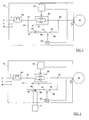
- la figure 1 est un schéma simplifié d'un circuit d'alimentation d'une charge électrique selon l'invention;
- la figure 2 est une variante du mode de réalisation illustré à la figure 1;
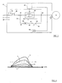
- la figure 3 représente le circuit d'alimentation de la figure 1 auquel est associé un dispositif à saut d'arc;
- la figure 4 représente des courbes de grandeurs électriques du circuit lors de l'apparition d'une surcharge.
- La figure 1 montre un circuit d'alimentation 10 d'une charge électrique telle qu'un moteur M mono- ou polyphasé. Le circuit d'alimentation 10 est relié aux conducteurs d'un réseau de distribution triphasé U, V, W.
- Entre le réseau et le moteur, se trouvent placés sur une ou plusieurs phases et en série un interrupteur électromécanique de protection 20 et un interrupteur électronique 30; l'interrupteur électronique 30 est piloté par un dispositif de commande à modulation d'impulsions 40 pour moduler l'énergie foumie au moteur. Pour des raisons de commodité, seuls sont représentés les éléments intéressant l'une des lignes de phase du circuit.
- Le moteur M est alimenté uniquement lorsque l'interrupteur électromécanique de protection 20, tel qu'un disjoncteur comprenant des contacts mobiles coopérant avec des contacts fixes, est fermé, puis que le dispositif de commande 40 a fermé l'interrupteur électronique 30, le courant passant par un chemin de courant principal C.
- L'interrupteur électronique 30 est piloté par le dispositif de commande à modulation d'impulsions 40 pour former ainsi un gradateur électronique afin de délivrer au moteur une énergie graduée pendant les phases de démarrage et de ralentissement de manière à en assurer la progressivité.
- L'interrupteur électronique 30 est constitué par deux thyristors montés tête bêche en parallèle ou par tout autre interrupteur à semi-conducteur bidirectionnel commandable; il est connecté par une bome amont 31 à l'interrupteur électromécanique de protection 20 et par une bome aval 32 au moteur M.
- En parallèle à l'interrupteur électronique 30, sur un chemin de courant dérivé C1, est branché de manière connue un contacteur électromécanique de shuntage 50 comprenant des contacts principaux 51, 52; le contacteur comprend aussi un électro-aimant dont la bobine 53 a des bomes reliées au dispositif de commande 40 et qui détermine l'ouverture et la fermeture des contacts 51, 52. Ces contacts sont fermés en dehors d'une phase de démarrage ou de freinage du moteur lorsqu'il est souhaité alimenter le moteur avec une énergie non modulée. La dérivation du courant par le chemin C1 du contacteur 50 permet de ne pas échauffer les thyristors.
- Enfin, en série et en amont du contacteur de shuntage 50 est branché un composant électrique 60 apte à établir une tension continue V aux bomes des thyristors lorsque les contacts 51, 52 du contacteur sont fermés. Le composant électrique 60 présente une bome amont 61 connectée à la bome amont 31 de l'interrupteur électronique 30 et une bome aval 62 connectée à la bome amont 51 du contacteur 50 dont la bome aval 52 est reliée à l'interrupteur statique 30.
- Le composant électrique 60 peut être constitué par une résistance R (figure 1) ou par un transformateur T (figure 2). L'utilisation du transformateur T peut permettre d'alimenter un circuit dérivé 11 du circuit 10.
- L'impédance de la résistance R ou l'impédance du primaire du transformateur T est choisie de manière à établir une tension V suffisante pour que les thyristors, sur lesquels le dispositif 40 envoie continuellement des impulsions de commande, soient conducteurs au passage d'une surintensité sur le chemin de courant principal C.
- La figure 3 montre le circuit de la figure 1 auquel est ajouté un dispositif électrique à saut d'arc 70 de type connu associé à l'interrupteur 20. Le dispositif 70 est par exemple une électrode de transfert d'arc, située d'une part à faible distance du contact fixe amont de l'interrupteur 20 raccordé au réseau, et reliée d'autre part à la bome aval 32 de l'interrupteur électronique 30. Le dispositif 70 a pour fonction de protéger l'interrupteur électronique 30, pendant une phase de son fonctionnement, en dérivant le courant lorsqu'une surintensité apparaît sur le chemin principal C de courant afin d'éviter que l'interrupteur 30 soit traversé par le courant d'arc engendré lors de l'ouverture des contacts de l'interrupteur 20.
- Le fonctionnement du circuit d'alimentation se fait de la manière suivante:
- L'interrupteur de protection 20 est fermé puis le dispositif de commande 40 applique à l'électrode de commande des thyristors des signaux d'allumage ou d'extinction pour rendre les thyristors conducteurs ou non conducteurs lors de la phase de démarrage du moteur tandis que le contacteur 50 reste ouvert.
- Lorsque le moteur a atteint une vitesse nominale, le dispositif de commande 40 shunte les thyristors en fermant le contacteur 50 qui foumit une énergie continue au moteur, le courant circulant dans les thyristors est alors nul.
- Lorsque le contacteur 50 est fermé, le dispositif 40 envoie continuellement des impulsions de commande aux thyristors qui ne sont cependant pas conducteurs en raison de la tension V à leurs bomes restant inférieure à la tension de seuil d'amorçage.
- La figure 4 illustre les allures du courant dans le circuit et de la tension aux bomes des thyristors lorsqu'un courant de surcharge, dû par exemple à un court-circuit, apparaît sur le chemin de courant C. Durant le court instant entre la détection du courant de surcharge et l'ouverture des contacts de l'interrupteur 20, le courant IC du chemin principal C augmente engendrant une augmentation du courant IC1 passant par le chemin de courant C1 lorsque le contacteur de shuntage 50 est fermé. En raison de la présence de la résistance 60, l'augmentation du courant IC1 entraîne une augmentation de la tension V aux bomes de l'interrupteur électronique 30 pour atteindre la tension d'amorçage, ce qui provoque la conduction des thyristors et donc le passage par ceux-ci d'un courant IT, représentant une partie du courant IC.
- Ainsi, lors d'une surintensité, le courant Ici augmente mais reste inférieur au courant de répulsion IR du contacteur correspondant au soudage des contacts.
Claims (4)
- Circuit pour l'alimentation protégée d'une charge électrique en courant altematif, le circuit (10) comprenant un interrupteur de protection (20) et un interrupteur électronique bidirectionnel (30) placé en série, en aval de l'interrupteur de protection (20) et piloté par un dispositif de commande (40) pour assurer un fonctionnement gradué de la charge, et comprenant en parallèle à l'interrupteur électronique (30) un contacteur de shuntage (50) assurant un fonctionnement continu de la charge, caractérisé en ce qu'est branché en série au contacteur de shuntage (50) et en amont de celui-ci un composant électrique (60) destiné à établir une tension continue (V) aux bomes de l'interrupteur électronique (30) et dont l'impédance est choisie de manière à rendre conducteur, lors de l'apparition d'un courant de surcharge dans le circuit et pendant une phase de fonctionnement continu de la charge, l'interrupteur électronique (30) sur lequel est envoyé périodiquement des impulsions de commande.
- Circuit d'alimentation selon la revendication 1, caractérisé en ce que le composant électrique (60) est une résistance.
- Circuit d'alimentation selon la revendication 1, caractérisé en ce que le composant électrique (60) est un transformateur qui alimente un circuit dérivé (11) du circuit d'alimentation (10).
- Circuit d'alimentation selon l'une quelconque des revendications précédentes, caractérisé en ce qu'il comprend un dispositif à saut d'arc (70) shuntant l'interrupteur électronique (30) en cas d'apparition d'un courant de surcharge pendant un fonctionnement gradué de la charge.
Applications Claiming Priority (2)
| Application Number | Priority Date | Filing Date | Title |
|---|---|---|---|
| FR9605956 | 1996-05-10 | ||
| FR9605956A FR2748612B1 (fr) | 1996-05-10 | 1996-05-10 | Circuit pour l'alimentation protegee d'une charge electrique |
Publications (2)
| Publication Number | Publication Date |
|---|---|
| EP0806781A1 true EP0806781A1 (fr) | 1997-11-12 |
| EP0806781B1 EP0806781B1 (fr) | 2002-09-11 |
Family
ID=9492097
Family Applications (1)
| Application Number | Title | Priority Date | Filing Date |
|---|---|---|---|
| EP97400951A Expired - Lifetime EP0806781B1 (fr) | 1996-05-10 | 1997-04-28 | Circuit pour l'alimentation protégée d'une charge électrique |
Country Status (9)
| Country | Link |
|---|---|
| US (1) | US5953189A (fr) |
| EP (1) | EP0806781B1 (fr) |
| AU (1) | AU716799B2 (fr) |
| BR (1) | BR9703106A (fr) |
| CZ (1) | CZ293753B6 (fr) |
| DE (1) | DE69715296T2 (fr) |
| FR (1) | FR2748612B1 (fr) |
| TW (1) | TW463440B (fr) |
| ZA (1) | ZA973974B (fr) |
Cited By (5)
| Publication number | Priority date | Publication date | Assignee | Title |
|---|---|---|---|---|
| NL1016791C2 (nl) * | 2000-12-04 | 2002-06-05 | Holec Holland Nv | Hybride elektrische schakelinrichting. |
| ES2367936A1 (es) * | 2008-02-05 | 2011-11-11 | Ls Industrial Systems Co. Ltd | Aparato limitador de corriente de pico. |
| EP2590314A1 (fr) * | 2011-11-03 | 2013-05-08 | ABB Technology AG | Onduleur et système électronique de puissance doté de tels systèmes onduleurs |
| WO2014029614A3 (fr) * | 2012-08-21 | 2014-10-23 | Siemens Aktiengesellschaft | Démarreur |
| WO2017153098A1 (fr) * | 2016-03-08 | 2017-09-14 | Siemens Aktiengesellschaft | Demarreur de moteur et procédé de diagnostic |
Families Citing this family (15)
| Publication number | Priority date | Publication date | Assignee | Title |
|---|---|---|---|---|
| EP1733470B1 (fr) | 2004-04-05 | 2012-08-15 | Siemens Aktiengesellschaft | Dispositif de commutation servant a faire fonctionner un moteur, et procede correspondant |
| US8072723B2 (en) * | 2007-06-19 | 2011-12-06 | General Electric Company | Resettable MEMS micro-switch array based on current limiting apparatus |
| FR2930091B1 (fr) * | 2008-04-09 | 2011-10-28 | Schneider Electric Ind Sas | Systeme a relais statique comprenant deux transistors de type jfet en serie |
| US8922957B2 (en) * | 2008-04-30 | 2014-12-30 | Keysight Technologies, Inc. | Dynamic switch contact protection |
| JP5286413B2 (ja) | 2009-06-25 | 2013-09-11 | 東芝三菱電機産業システム株式会社 | 低周波遮断器 |
| US8619395B2 (en) | 2010-03-12 | 2013-12-31 | Arc Suppression Technologies, Llc | Two terminal arc suppressor |
| KR101044492B1 (ko) * | 2010-04-23 | 2011-06-27 | 엘에스산전 주식회사 | 하이브리드 한류기 |
| JP5106606B2 (ja) | 2010-09-27 | 2012-12-26 | 三菱電機株式会社 | 放電システムおよび電動車両 |
| CN102244510A (zh) * | 2011-05-18 | 2011-11-16 | 广州市金矢电子有限公司 | 触发节能装置及晶闸管开关 |
| WO2014075742A1 (fr) * | 2012-11-19 | 2014-05-22 | Siemens Aktiengesellschaft | Appareil de commutation pour la commande de l'alimentation en énergie d'un moteur électrique disposé en aval |
| US9270119B2 (en) * | 2013-05-24 | 2016-02-23 | Eaton Corporation | High voltage direct current transmission and distribution system |
| CN104660107A (zh) * | 2013-11-21 | 2015-05-27 | 河南省济源市矿用电器有限责任公司 | 矿用隔爆兼本安质安全型双接触器低压交流软启动器 |
| CN104730441B (zh) * | 2013-12-20 | 2018-07-17 | 中国科学院宁波材料技术与工程研究所 | 晶闸管故障检测装置 |
| CN104752080A (zh) * | 2013-12-31 | 2015-07-01 | 北京新宇航世纪科技有限公司 | 具有消弧功能的感性负载直流开关 |
| EP3410601A1 (fr) * | 2017-06-02 | 2018-12-05 | General Electric Technology GmbH | Appareil de commutation |
Citations (2)
| Publication number | Priority date | Publication date | Assignee | Title |
|---|---|---|---|---|
| FR2227624A1 (fr) * | 1973-04-26 | 1974-11-22 | Franklin Electric Co Inc | |
| EP0633584A1 (fr) * | 1993-07-05 | 1995-01-11 | Schneider Electric Sa | Dispositif de protection et de commande pour charge électrique |
Family Cites Families (1)
| Publication number | Priority date | Publication date | Assignee | Title |
|---|---|---|---|---|
| FR2584529B1 (fr) * | 1985-07-04 | 1995-01-06 | Merlin Gerin | Disjoncteur-contacteur electrique, notamment pour des batteries de condensateurs |
-
1996
- 1996-05-10 FR FR9605956A patent/FR2748612B1/fr not_active Expired - Lifetime
-
1997
- 1997-04-28 EP EP97400951A patent/EP0806781B1/fr not_active Expired - Lifetime
- 1997-04-28 DE DE69715296T patent/DE69715296T2/de not_active Expired - Lifetime
- 1997-05-08 AU AU20098/97A patent/AU716799B2/en not_active Ceased
- 1997-05-08 ZA ZA9703974A patent/ZA973974B/xx unknown
- 1997-05-09 US US08/854,164 patent/US5953189A/en not_active Expired - Lifetime
- 1997-05-09 BR BR9703106A patent/BR9703106A/pt not_active Application Discontinuation
- 1997-05-09 CZ CZ19971423A patent/CZ293753B6/cs not_active IP Right Cessation
- 1997-05-30 TW TW086107571A patent/TW463440B/zh not_active IP Right Cessation
Patent Citations (2)
| Publication number | Priority date | Publication date | Assignee | Title |
|---|---|---|---|---|
| FR2227624A1 (fr) * | 1973-04-26 | 1974-11-22 | Franklin Electric Co Inc | |
| EP0633584A1 (fr) * | 1993-07-05 | 1995-01-11 | Schneider Electric Sa | Dispositif de protection et de commande pour charge électrique |
Cited By (12)
| Publication number | Priority date | Publication date | Assignee | Title |
|---|---|---|---|---|
| NL1016791C2 (nl) * | 2000-12-04 | 2002-06-05 | Holec Holland Nv | Hybride elektrische schakelinrichting. |
| WO2002047100A1 (fr) * | 2000-12-04 | 2002-06-13 | Holec Holland N.V. | Dispositif de commutation electrique hybride |
| US7339288B2 (en) | 2000-12-04 | 2008-03-04 | Eaton Electric N.V. | Hybrid electrical switching device |
| US7612471B2 (en) | 2000-12-04 | 2009-11-03 | Eaton Electric N.V. | Hybrid electrical switching device |
| ES2367936A1 (es) * | 2008-02-05 | 2011-11-11 | Ls Industrial Systems Co. Ltd | Aparato limitador de corriente de pico. |
| EP2590314A1 (fr) * | 2011-11-03 | 2013-05-08 | ABB Technology AG | Onduleur et système électronique de puissance doté de tels systèmes onduleurs |
| WO2014029614A3 (fr) * | 2012-08-21 | 2014-10-23 | Siemens Aktiengesellschaft | Démarreur |
| US10253742B2 (en) | 2012-08-21 | 2019-04-09 | Siemens Aktiengesellschaft | Motor starter |
| WO2017153098A1 (fr) * | 2016-03-08 | 2017-09-14 | Siemens Aktiengesellschaft | Demarreur de moteur et procédé de diagnostic |
| CN108781046A (zh) * | 2016-03-08 | 2018-11-09 | 西门子股份公司 | 电机启动器和诊断方法 |
| US10873279B2 (en) | 2016-03-08 | 2020-12-22 | Siemens Aktiengesellschaft | Motor starter and diagnosis method |
| CN108781046B (zh) * | 2016-03-08 | 2023-02-17 | 西门子股份公司 | 电机启动器和诊断方法 |
Also Published As
| Publication number | Publication date |
|---|---|
| AU2009897A (en) | 1997-11-13 |
| FR2748612A1 (fr) | 1997-11-14 |
| EP0806781B1 (fr) | 2002-09-11 |
| CZ142397A3 (cs) | 1998-12-16 |
| CZ293753B6 (cs) | 2004-07-14 |
| FR2748612B1 (fr) | 1998-06-19 |
| ZA973974B (en) | 1997-12-02 |
| DE69715296T2 (de) | 2003-06-12 |
| DE69715296D1 (de) | 2002-10-17 |
| US5953189A (en) | 1999-09-14 |
| AU716799B2 (en) | 2000-03-09 |
| TW463440B (en) | 2001-11-11 |
| BR9703106A (pt) | 1998-06-30 |
Similar Documents
| Publication | Publication Date | Title |
|---|---|---|
| EP0806781B1 (fr) | Circuit pour l'alimentation protégée d'une charge électrique | |
| JP3894576B2 (ja) | サージ抵抗継電器スイッチング回路 | |
| US3868549A (en) | Circuit for protecting contacts against damage from arcing | |
| KR20050092721A (ko) | 아크-결함 검출 회로 차단기 시스템 | |
| FR2748167A1 (fr) | Dispositif de commande d'une charge inductive | |
| FR2618276A1 (fr) | Dispositif de commutation electronique. | |
| FR2574984A1 (fr) | Dispositif d'extinction d'arc | |
| EP0462034B1 (fr) | Dispositif de protection pour relais statique à semi-conducteurs | |
| EP0841670A1 (fr) | Transformateur de courant, déclencheur et disjoncteur comportant un tel transformateur | |
| US2569133A (en) | Series capacitor protective system | |
| BE1005336A0 (fr) | Telerupteur a dispositif de limitation de courant. | |
| CH618273A5 (fr) | ||
| US6680836B1 (en) | Timed tripping circuit for an electromechanical switching device | |
| JP3445244B2 (ja) | 変成器過渡電流制限装置 | |
| FR3099289A1 (fr) | Contacteur et procédé de commande d’un contacteur | |
| EP0780861A1 (fr) | Dispositif électrique à communtation d'arc | |
| EP0854491A1 (fr) | Appareil contacteur-disjoncteur | |
| EP3159991B1 (fr) | Dispositif et procede de limitation d'un premier pic de courant dans un reseau electrique | |
| FR2707437A1 (fr) | Dispositif de protection et de commande pour charge électrique. | |
| FR2702315A1 (fr) | Interrupteur différentiel de protection contre les courants de défaut et les surtensions. | |
| EP0461054A1 (fr) | Procédé et dispositif de limitation de surintensités dans un circuit électrique | |
| JPH0346934B2 (fr) | ||
| FR2538608A1 (fr) | Dispositif electronique de protection du circuit contacteur d'un relais et relais equipe d'un tel dispositif | |
| FR2775847A1 (fr) | Dispositifs de protection differentielle, appareil electrique et installation electrique comportant un tel dispositif | |
| FR2703858A1 (fr) | Dispositif de protection contre les surintensités pour un régulateur. |
Legal Events
| Date | Code | Title | Description |
|---|---|---|---|
| PUAI | Public reference made under article 153(3) epc to a published international application that has entered the european phase |
Free format text: ORIGINAL CODE: 0009012 |
|
| AK | Designated contracting states |
Kind code of ref document: A1 Designated state(s): DE IT SE |
|
| 17P | Request for examination filed |
Effective date: 19980512 |
|
| RAP1 | Party data changed (applicant data changed or rights of an application transferred) |
Owner name: SCHNEIDER ELECTRIC INDUSTRIES SA |
|
| RAP1 | Party data changed (applicant data changed or rights of an application transferred) |
Owner name: SCHNEIDER ELECTRIC INDUSTRIES SA |
|
| GRAG | Despatch of communication of intention to grant |
Free format text: ORIGINAL CODE: EPIDOS AGRA |
|
| GRAG | Despatch of communication of intention to grant |
Free format text: ORIGINAL CODE: EPIDOS AGRA |
|
| GRAH | Despatch of communication of intention to grant a patent |
Free format text: ORIGINAL CODE: EPIDOS IGRA |
|
| 17Q | First examination report despatched |
Effective date: 20020220 |
|
| GRAH | Despatch of communication of intention to grant a patent |
Free format text: ORIGINAL CODE: EPIDOS IGRA |
|
| GRAA | (expected) grant |
Free format text: ORIGINAL CODE: 0009210 |
|
| RAP1 | Party data changed (applicant data changed or rights of an application transferred) |
Owner name: SCHNEIDER ELECTRONIC INDUSTRIES SAS |
|
| RAP1 | Party data changed (applicant data changed or rights of an application transferred) |
Owner name: SCHNEIDER ELECTRIC INDUSTRIES SAS |
|
| AK | Designated contracting states |
Kind code of ref document: B1 Designated state(s): DE IT SE |
|
| REF | Corresponds to: |
Ref document number: 69715296 Country of ref document: DE Date of ref document: 20021017 |
|
| PLBE | No opposition filed within time limit |
Free format text: ORIGINAL CODE: 0009261 |
|
| STAA | Information on the status of an ep patent application or granted ep patent |
Free format text: STATUS: NO OPPOSITION FILED WITHIN TIME LIMIT |
|
| 26N | No opposition filed |
Effective date: 20030612 |
|
| REG | Reference to a national code |
Ref country code: DE Ref legal event code: R084 Ref document number: 69715296 Country of ref document: DE Effective date: 20111228 |
|
| PGFP | Annual fee paid to national office [announced via postgrant information from national office to epo] |
Ref country code: SE Payment date: 20150410 Year of fee payment: 19 Ref country code: DE Payment date: 20150325 Year of fee payment: 19 |
|
| PGFP | Annual fee paid to national office [announced via postgrant information from national office to epo] |
Ref country code: IT Payment date: 20150423 Year of fee payment: 19 |
|
| REG | Reference to a national code |
Ref country code: DE Ref legal event code: R119 Ref document number: 69715296 Country of ref document: DE |
|
| REG | Reference to a national code |
Ref country code: SE Ref legal event code: EUG |
|
| PG25 | Lapsed in a contracting state [announced via postgrant information from national office to epo] |
Ref country code: DE Free format text: LAPSE BECAUSE OF NON-PAYMENT OF DUE FEES Effective date: 20161101 |
|
| PG25 | Lapsed in a contracting state [announced via postgrant information from national office to epo] |
Ref country code: IT Free format text: LAPSE BECAUSE OF NON-PAYMENT OF DUE FEES Effective date: 20160428 Ref country code: SE Free format text: LAPSE BECAUSE OF NON-PAYMENT OF DUE FEES Effective date: 20160429 |