EP0806825A2 - Système de protection différentielle - Google Patents
Système de protection différentielle Download PDFInfo
- Publication number
- EP0806825A2 EP0806825A2 EP97101634A EP97101634A EP0806825A2 EP 0806825 A2 EP0806825 A2 EP 0806825A2 EP 97101634 A EP97101634 A EP 97101634A EP 97101634 A EP97101634 A EP 97101634A EP 0806825 A2 EP0806825 A2 EP 0806825A2
- Authority
- EP
- European Patent Office
- Prior art keywords
- residual current
- current protection
- switching device
- protective
- protection switching
- Prior art date
- Legal status (The legal status is an assumption and is not a legal conclusion. Google has not performed a legal analysis and makes no representation as to the accuracy of the status listed.)
- Granted
Links
- 230000001681 protective effect Effects 0.000 claims abstract description 75
- 230000007935 neutral effect Effects 0.000 claims abstract description 12
- 239000004020 conductor Substances 0.000 claims description 97
- 239000004065 semiconductor Substances 0.000 claims description 17
- 238000002955 isolation Methods 0.000 claims description 11
- 239000003990 capacitor Substances 0.000 claims description 5
- 230000000694 effects Effects 0.000 claims description 4
- 238000009499 grossing Methods 0.000 claims description 4
- 238000001514 detection method Methods 0.000 abstract description 7
- 238000004804 winding Methods 0.000 description 12
- 238000011156 evaluation Methods 0.000 description 4
- 238000010586 diagram Methods 0.000 description 2
- 230000009993 protective function Effects 0.000 description 2
- 230000035945 sensitivity Effects 0.000 description 2
- 238000013459 approach Methods 0.000 description 1
- 230000007547 defect Effects 0.000 description 1
- 230000001419 dependent effect Effects 0.000 description 1
- 238000005553 drilling Methods 0.000 description 1
- 230000006870 function Effects 0.000 description 1
- 238000009413 insulation Methods 0.000 description 1
- 238000012544 monitoring process Methods 0.000 description 1
- 238000000926 separation method Methods 0.000 description 1
- 230000006641 stabilisation Effects 0.000 description 1
- 238000011105 stabilization Methods 0.000 description 1
- 239000000758 substrate Substances 0.000 description 1
- 230000001960 triggered effect Effects 0.000 description 1
Images

Classifications
-
- H—ELECTRICITY
- H02—GENERATION; CONVERSION OR DISTRIBUTION OF ELECTRIC POWER
- H02H—EMERGENCY PROTECTIVE CIRCUIT ARRANGEMENTS
- H02H3/00—Emergency protective circuit arrangements for automatic disconnection directly responsive to an undesired change from normal electric working condition with or without subsequent reconnection ; integrated protection
- H02H3/26—Emergency protective circuit arrangements for automatic disconnection directly responsive to an undesired change from normal electric working condition with or without subsequent reconnection ; integrated protection responsive to difference between voltages or between currents; responsive to phase angle between voltages or between currents
- H02H3/32—Emergency protective circuit arrangements for automatic disconnection directly responsive to an undesired change from normal electric working condition with or without subsequent reconnection ; integrated protection responsive to difference between voltages or between currents; responsive to phase angle between voltages or between currents involving comparison of the voltage or current values at corresponding points in different conductors of a single system, e.g. of currents in go and return conductors
- H02H3/33—Emergency protective circuit arrangements for automatic disconnection directly responsive to an undesired change from normal electric working condition with or without subsequent reconnection ; integrated protection responsive to difference between voltages or between currents; responsive to phase angle between voltages or between currents involving comparison of the voltage or current values at corresponding points in different conductors of a single system, e.g. of currents in go and return conductors using summation current transformers
- H02H3/338—Emergency protective circuit arrangements for automatic disconnection directly responsive to an undesired change from normal electric working condition with or without subsequent reconnection ; integrated protection responsive to difference between voltages or between currents; responsive to phase angle between voltages or between currents involving comparison of the voltage or current values at corresponding points in different conductors of a single system, e.g. of currents in go and return conductors using summation current transformers also responsive to wiring error, e.g. loss of neutral, break
-
- G—PHYSICS
- G01—MEASURING; TESTING
- G01R—MEASURING ELECTRIC VARIABLES; MEASURING MAGNETIC VARIABLES
- G01R19/00—Arrangements for measuring currents or voltages or for indicating presence or sign thereof
- G01R19/145—Indicating the presence of current or voltage
- G01R19/155—Indicating the presence of voltage
-
- G—PHYSICS
- G01—MEASURING; TESTING
- G01R—MEASURING ELECTRIC VARIABLES; MEASURING MAGNETIC VARIABLES
- G01R31/00—Arrangements for testing electric properties; Arrangements for locating electric faults; Arrangements for electrical testing characterised by what is being tested not provided for elsewhere
- G01R31/50—Testing of electric apparatus, lines, cables or components for short-circuits, continuity, leakage current or incorrect line connections
- G01R31/52—Testing for short-circuits, leakage current or ground faults
-
- G—PHYSICS
- G01—MEASURING; TESTING
- G01R—MEASURING ELECTRIC VARIABLES; MEASURING MAGNETIC VARIABLES
- G01R31/00—Arrangements for testing electric properties; Arrangements for locating electric faults; Arrangements for electrical testing characterised by what is being tested not provided for elsewhere
- G01R31/50—Testing of electric apparatus, lines, cables or components for short-circuits, continuity, leakage current or incorrect line connections
- G01R31/54—Testing for continuity
-
- H—ELECTRICITY
- H02—GENERATION; CONVERSION OR DISTRIBUTION OF ELECTRIC POWER
- H02H—EMERGENCY PROTECTIVE CIRCUIT ARRANGEMENTS
- H02H1/00—Details of emergency protective circuit arrangements
- H02H1/0007—Details of emergency protective circuit arrangements concerning the detecting means
-
- H—ELECTRICITY
- H02—GENERATION; CONVERSION OR DISTRIBUTION OF ELECTRIC POWER
- H02H—EMERGENCY PROTECTIVE CIRCUIT ARRANGEMENTS
- H02H3/00—Emergency protective circuit arrangements for automatic disconnection directly responsive to an undesired change from normal electric working condition with or without subsequent reconnection ; integrated protection
- H02H3/14—Emergency protective circuit arrangements for automatic disconnection directly responsive to an undesired change from normal electric working condition with or without subsequent reconnection ; integrated protection responsive to occurrence of voltage on parts normally at earth potential
-
- H—ELECTRICITY
- H02—GENERATION; CONVERSION OR DISTRIBUTION OF ELECTRIC POWER
- H02H—EMERGENCY PROTECTIVE CIRCUIT ARRANGEMENTS
- H02H3/00—Emergency protective circuit arrangements for automatic disconnection directly responsive to an undesired change from normal electric working condition with or without subsequent reconnection ; integrated protection
- H02H3/16—Emergency protective circuit arrangements for automatic disconnection directly responsive to an undesired change from normal electric working condition with or without subsequent reconnection ; integrated protection responsive to fault current to earth, frame or mass
-
- H—ELECTRICITY
- H02—GENERATION; CONVERSION OR DISTRIBUTION OF ELECTRIC POWER
- H02H—EMERGENCY PROTECTIVE CIRCUIT ARRANGEMENTS
- H02H5/00—Emergency protective circuit arrangements for automatic disconnection directly responsive to an undesired change from normal non-electric working conditions with or without subsequent reconnection
- H02H5/10—Emergency protective circuit arrangements for automatic disconnection directly responsive to an undesired change from normal non-electric working conditions with or without subsequent reconnection responsive to mechanical injury, e.g. rupture of line, breakage of earth connection
- H02H5/105—Emergency protective circuit arrangements for automatic disconnection directly responsive to an undesired change from normal non-electric working conditions with or without subsequent reconnection responsive to mechanical injury, e.g. rupture of line, breakage of earth connection responsive to deterioration or interruption of earth connection
-
- H—ELECTRICITY
- H02—GENERATION; CONVERSION OR DISTRIBUTION OF ELECTRIC POWER
- H02H—EMERGENCY PROTECTIVE CIRCUIT ARRANGEMENTS
- H02H11/00—Emergency protective circuit arrangements for preventing the switching-on in case an undesired electric working condition might result
- H02H11/001—Emergency protective circuit arrangements for preventing the switching-on in case an undesired electric working condition might result in case of incorrect or interrupted earth connection
Definitions
- the invention relates to a DI protective switching device according to the preamble of patent claim 1.
- Residual current circuit breakers are mechanical switching devices that are designed to interrupt the associated circuits by opening contacts when residual currents occur.
- a residual current circuit breaker for insulation monitoring of electrical circuits with a summation current transformer which has a primary winding formed from a phase conductor and a neutral conductor and a secondary winding, is known from EP 0655 820 A1.
- the secondary winding detects the fault current and controls a relay acting on switching contacts via an amplifier and a limit switch.
- Residual current circuit breakers in which the function of detection, evaluation or shutdown depend on the mains voltage are referred to as mains voltage-dependent DI residual current circuit breakers.
- Such a circuit breaker recognizes the need to isolate all poles, i.e. including the protective conductor (PE), by either the difference between the current flowing in and out through the phase conductor (L) and the neutral conductor (N) or the current through the protective conductor ( PE) exceeds a certain amount.
- the previously known residual current circuit breakers are not able to detect various fault situations in connection with the protective conductor (PE). For example, a break, i.e. the absence of the protective conductor (PE), is not recognizable, since if the protective conductor (PE) is not present, no current can flow through it.
- a break i.e. the absence of the protective conductor (PE)
- the protective conductor (PE) is not present, no current can flow through it.
- the residual current circuit breaker can only be activated by the tradesman as the sole current conductor. If a foreign phase is tapped, there is no guarantee that the protective earth path will be available.
- the residual current circuit breakers cannot detect the mains voltage on the protective conductor (PE) and use it for disconnection.
- the residual current circuit breaker only interrupts the circuit when a current of a specific current flows through the housing of the connected device and, for example, via the craftsman. Since this current initially flows at full mains voltage, a very high, critical initial body current results, which is only limited by the body resistance. This initial body flow can be fatal to the user.
- the invention is therefore based on the object of a residual current circuit breaker to improve the type mentioned at the outset so that the disadvantages mentioned above are avoided and in particular fault states of the protective conductor (PE) are recognized.
- PE protective conductor
- the residual current circuit breaker recognizes fault conditions with regard to the protective conductor and effects an all-pole disconnection of the main circuit.
- a potential approximation to earth at a sensor is required for the detection of a live PE conductor, which e.g. is achieved by an ohmic and / or capacitive impedance, for example by the user, when the user touches an ON button made of conductive material.
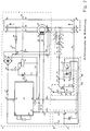
- FIG. 1 shows a preferred embodiment of a residual current circuit breaker according to the invention.
- the L-phase conductor 1 is connected to a protective impedance 5 via a line 4, and the N-neutral conductor 2 is connected to a protective impedance 7 via a line 6.
- the protective impedances 5, 7 are interconnected on the output side via conductors 8, 9 at a node 10.
- Point 10 is connected via a line 11 to a further protective impedance 12, which is connected on the output side via a conductor 13 to a device 14 for detecting the protective conductor state.
- the protective impedances 5, 7 and 12 serve to limit the current.
- the device 14 is also connected via a line 15 to the protective conductor 3 and via a line 16 to a sensor 17.
- the sensor 17 is a button made of a conductive material, which must be touched by an operator.
- the sensor 17 is located, for example, on the housing of the connected device.
- the output of the device 14 is connected via a conductor 18 to a switching stage 19 which switches a DI residual current circuit breaker 21 via a line 20.
- the DI residual current circuit breaker 21 is connected to a summation current transformer 22, the primary winding of which is formed by the phase conductor 1 and the neutral conductor 2.
- the summation current transformer 22 also has a secondary winding, which leads induced voltages via lines 23, 24 to evaluation electronics contained in the DI switch 21.
- the DI switch 21 is mechanically coupled to switch contacts 25, 26, 27, which are connected in lines 1, 2, 3. The entire arrangement shown in FIG. 1 forms the DI protective switching device.
- the device 14 detects this fault condition due to the current not flowing via the conductor 15 to the protective conductor 3 and switches the DI protective switch 21 via a potential-separated switching stage 19, which switches the Switch contacts 25, 26, 27 opens and thus interrupts the conductors 1, 2, 3 at all poles.
- the device 14 can also recognize a further fault condition, namely the presence of a phase or mains voltage on the protective conductor 3.
- the sensor surface 17 made of a conductive material is used for this purpose.
- the user touches the sensor surface 17, as a result of which the user's impedance 17 a at sensor 17 approaches the earth. If phase or mains voltage is present on the protective conductor 3, a voltage difference arises to the sensor surface 17, which is approximately at earth potential due to the user's touch, which is recognized by the device 14 as an error state.
- the device 14 switches the DI switch 21 via the switching stage 19, which opens the switch contacts 25, 26, 27.
- FIG. 2 shows a detailed view of the preferred one shown in FIG. 1 DI fault current protection switching device with protective conductor status detection according to the invention.
- the same reference numbers designate identical components.
- the protective impedances 5, 7, 12 are connected via the line 13 to the device 14 for detecting the state of the PE protective conductor 3.
- the line 13 branches in the device 14 at a branching point 28 into two line sections 29, 30, the first line section 29 being connected to a semiconductor switch 31 and the second line section 30 being connected to a potential isolation stage 32.
- the semiconductor switch 31 is preferably a MOSFET, for example a normally-off n-channel MOSFET, as shown in FIG. 2.
- Line 29 is connected to the DRAIN connection of MOSFET 31.
- SOURCE and ground of the MOSFET 31 are interconnected and are connected via a line 32 with the node 33 to the line 15, which leads to the protective conductor 3.
- the gate of the semiconductor switch 31 is connected via a line 34 to a node 37 lying between a protective resistor 35 and a load resistor 36.
- the protective or leakage resistor 35 is connected via the line 16 to the sensor 17.
- the load resistor 36 is connected between the nodes 33 and 37.
- the potential isolation stage 32 is located in the device 14. The potential isolation stage is connected on the input side via the lines 30, 38 between the branching point 28 and the line 15 leading to the PE protective conductor 3.
- the potential isolation stage 32 shown in FIG. 2 preferably consists of an optocoupler.
- the potential separation between the device 14 and the downstream switching stage 19 can, however, also take place via any other potential-isolating components, such as, for example, triac couplers, opto-field effect transistors, Piezo coupler, transformer or relay.
- the potential isolation stage 32 in the form of an optocoupler contains a light-emitting diode 39 on the input side, which lies between the lines 30 and 38.
- the potential isolation stage 32 has a light-sensitive transistor 40 which becomes conductive when light is received which is emitted by the light-emitting diode 39.
- the emitter of transistor 40 is connected to node 41 via a conductor 18b, and the collector of transistor 40 is connected to node 42 of switching stage 19 via a conductor 18a.
- the switching stage 19 contains a semiconductor switch 43, for example an NPN transistor, as shown in FIG. 2.
- the base of transistor 43 is connected to node 42 and the emitter to node 41.
- a smoothing capacitor 44 is connected in parallel to the base-emitter junction of transistor 43 between nodes 41 and 42.
- the switching stage 19 also has two current limiting resistors 45, 46 for the semiconductor switch 43.
- the first current limiting resistor 45 is arranged between the base 42 of the semiconductor switch 43 and a node 47, which is at the potential of a positive operating voltage (+ U b ) of an integrated circuit 48.
- the second current limiting resistor 46 of the switching stage 19 is connected between the collector of the semiconductor switch 43 and via a line 49a to a node 50.
- a secondary winding 52 of the summation current transformer 22 is connected to node 51 via line 23 and to node 50 via line 24.
- a converter terminating resistor 53 is connected between the two nodes 50, 51 in parallel to the secondary angle 52.
- the node 50 is connected to a connection 49, and the node 51 is connected to a connection point 54 of the integrated circuit 48.
- the integrated circuit 48 receives the supply voltage via two operating voltage connections 55, 56, the first connection 55 being at a positive operating voltage potential (+ U b ) and the second connection 56 at a negative operating voltage potential (-U b ).
- the two operating voltage connections 55, 56 of the integrated circuit 48 are internal to an IC several Z-diodes connected in series connected diode chain, which serves for stabilization.
- the connection point 49 is connected to an internal IC node, which lies in the middle of the Z-diode chain. Thus, the connection point 49 is at half the operating voltage and has a reference potential.
- the voltage supply of the integrated circuit 48 via the connections 55, 56 is ensured by a rectifier circuit 60, which taps the AC voltage on the phase conductor 1 and the neutral conductor 2 at points 61, 62 via the conductors 63, 64, rectifies and a DC voltage between the Nodes 65 and 66 provides.
- the node 65 is connected via a current limiting resistor 67 to the node 47, which supplies the IC 48 at the terminal 55 with the positive operating voltage (+ U b ).
- the node 66 supplies the IC 48 via the terminal 56 with the negative operating voltage (-U b ).
- the integrated circuit 48 also has two further connections 57, 58, between which an adjustable resistor 59 a is connected. The sensitivity of the integrated circuit 48 and thus the trigger value of the DI switch 21 can be set by means of the adjusting resistor 59 a.
- the integrated circuit 48 has an output connection 59 for emitting control pulses, which is connected via a control line 68 to a semiconductor switch 69, preferably a thyristor.
- the control line 68 starting from the output terminal 59 of the IC 48 controls the gate of the thyristor 69.
- the anode of the thyristor 69 shown in FIG. 2 is connected to a node 70 which is at a positive DC voltage potential via a current limiting resistor 71 at the node 65.
- the cathode of the thyristor 69 is connected via a line 72 to a connecting line 73 between the rectifier circuit 60 and the node 66.
- a quiescent current release relay 74 is connected in parallel with the thyristor 69 between the node 70 and the line 73.
- the quiescent current release relay 74 is mechanically connected the switching contacts 25, 26, 27 of the conductors 1, 2, 3 and a switch 75, by means of which the conductor 64 can be interrupted.
- the contacts 25, 26, 27 and the switch 75 can be actuated via a switch 76 or a switch to activate the circuit breaker.
- the DI switch 21 also has a test button 77, which is connected on the one hand via the node 78 to the operating current supply line 63 and on the other hand is connected in series with a resistor 79 for setting a test current to the neutral conductor 2.
- the residual current circuit breaker works in normal operation if the protective conductor 3 is correctly connected, no phase occurs on the protective conductor 3 and no residual current flows on the output or consumer side.
- the switching contacts 25, 26, 27 are closed and the input voltage is switched through the conductors 1, 2, 3 to the output or to the consumer side.
- Pressing the button 76 simultaneously causes the switch 75 to be closed, as a result of which an operating current is supplied to the rectifier circuit 60 via the operating current feed line 64.
- the rectifier circuit 60 supplies a positive voltage at node 70 at node 65 and after a corresponding voltage drop at current limiting resistor 71.
- quiescent current release relay 74 picks up and keeps contacts 25, 26, 27 and 75 closed after button 76 is released.
- the sum current transformer is in the secondary winding 52 22, whose primary windings are formed by conductors 1 and 2, induces a current.
- the induced current is conducted via lines 23, 24 and causes a voltage drop across the terminating resistor 53 of the summation current transformer 22. Due to the voltage drop across the resistor 53, the integrated circuit 48 receives a signal via the connections 49 and 54 which corresponds to the level of the fault current .
- the sensitivity of the integrated circuit 48 and thus the level of the trigger value can be set by means of the adjusting resistor 59 a.
- the integrated circuit 48 If the voltage between the connections 49 and 54 or the voltage across the terminating resistor 53 exceeds the set trigger value, the integrated circuit 48 outputs a control signal at the output 59 via the control line 68 to the gate of the thyristor 69 and ignites it.
- the fired thyristor 69 short-circuits the quiescent current release relay 74 connected in parallel with it, the relay 74 drops out and opens the switch contacts 25, 26, 27 and the switch 75.
- the switch contacts 25, 26, 27 By opening the switch contacts 25, 26, 27, the conductors 1, 2, 3 interrupted and thus the output side of the residual current circuit breaker separated from the input.
- the voltage supply for the residual current circuit breaker is interrupted by opening the switch 75.
- the residual current circuit breaker according to the invention also has additional protective functions since, in addition to the occurrence of a residual current, it also detects other error states.
- the device 14 recognizes the residual current circuit breaker as a further fault condition, a non-connected or interrupted PE protective conductor 3 and the presence of a voltage or phase on the PE protective conductor 3.
- the blocked transistor 43 prevents a short circuit between the connection point 49 and the connection 56, which has a negative operating voltage (-U b ), via line 49 a, resistor 46 and line 56a.
- a negative operating voltage (-U b )
- the IC 48 does not emit a control pulse via the control line 68 to the thyristor 69, which thereby remains blocked and does not short-circuit the relay 74.
- the switch contacts 25, 26, 27 and 75 remain closed as long as a current flows to the protective conductor 3 on the input side via the potential isolating stage 32 in the device 14 and no fault current is detected by the summation current transformer 22.
- a non-connected or interrupted protective conductor 3 thus immediately triggers the switching contacts 25, 26, 27 and immediately reliably separates the voltage input from the consumer-side output.
- the residual current circuit breaker according to the invention with detection of the protective conductor status cannot be switched on by means of the key 76 when the protective conductor 3 is not connected.
- the operator is informed by a display device that the protective conductor 3 is not connected or interrupted.
- the device 14 In addition to an interrupted or not connected protective conductor 3, the device 14 detects the presence of a voltage or a phase on the protective conductor 3 as a further fault condition.
- a current derived through line 15 flows via line 38, light-emitting diode 39 and line 30 or via line 32, semiconductor switch 31 and line 29 to line 13 and from there via protective impedances 12, 7 or 5 to neutral conductor 2.
- the n-channel MOSFET 31 shown in FIG. 2 limits the negative half-waves through its internal substrate diode, while the positive half-waves control the light-sensitive transistor 40 of the potential isolation stage 32 via the light-emitting diode 39.
- Controlled transistor 40 initially corresponds to normal operation, prevents the semiconductor switch 43 contained in the switching stage 19 from switching through and thus triggers the DI switch 21.
- the gate of the The semiconductor switch 31 is drawn via the line 34, the bleeder resistor 35, the line 16, the sensor surface 17 and the impedance 17 a (not shown in FIG. 2) of the user against earth potential.
- the semiconductor switch 31 becomes conductive and shorts the light-emitting diode 39.
- This causes the transistor 40 to be blocked and the smoothing capacitor 44 in the switching stage 19 to be charged via the resistor 45.
- the transistor 43 in the switching stage 19 switches on, and an asymmetry in the supply voltage at the IC-internal window comparator is caused.
- the IC 48 outputs a control pulse via the control line 68 to the gate of the thyristor 69, which fires and short-circuits the quiescent current release relay 74.
- the short-circuited relay drops out and opens the switch contacts 25, 26, 27 and the switch 75.
- this fault condition is recognized by the device 14 when the user touches the sensor surface 17 and leads to the immediate disconnection of the consumer-side output from the input of the residual current circuit breaker.
- the residual current circuit breaker according to the invention does not trigger only when a residual current has already flowed to earth via the user or craftsman, but in this case cannot be switched on at all.
- An additional advantage is that there is no shutdown when drilling into a foreign phase, i.e. Protection via switched PE remains.
- the fault current circuit breaker described above in connection with FIGS. 1 and 2 leads to incorrect wiring Networks or missing connections without additional windings on the summation current transformer 22 are recognized.
- the residual current circuit breaker according to the invention can no longer be switched on and additionally protects the user against errors in the connection of the protective conductor 3, against interruptions in the protective conductor 3 and against the occurrence of mains voltage on the protective conductor 3. These errors were not recognized and taken into account in the previously known residual current circuit breakers .
- auxiliary windings on the summation current transformer 22 could be omitted, since the electronic device 14 for detecting the protective conductor state acts directly on the IC 48 located in the DI switch 21 via the switching stage 19 and does not allow a fault current to flow through the auxiliary windings.
- the user is informed of the cause of the tripping or the reason why the residual current circuit breaker cannot be switched on by evaluation electronics when the residual current circuit breaker is triggered, if the residual current circuit breaker cannot be switched on.
- the user is shown via a display device connected to the evaluation electronics whether the DI switch 21 has tripped due to an error current that has occurred, an interrupted or not connected PE protective conductor 3 or because of a mains voltage that has occurred on the protective conductor 3, or does not switch on leaves. This display makes it much easier for the user to rectify the cause of the error.
Landscapes
- Physics & Mathematics (AREA)
- General Physics & Mathematics (AREA)
- Engineering & Computer Science (AREA)
- Power Engineering (AREA)
- Emergency Protection Circuit Devices (AREA)
- Control Of Motors That Do Not Use Commutators (AREA)
- Noodles (AREA)
- Amplifiers (AREA)
- Interface Circuits In Exchanges (AREA)
- Driving Mechanisms And Operating Circuits Of Arc-Extinguishing High-Tension Switches (AREA)
Applications Claiming Priority (2)
| Application Number | Priority Date | Filing Date | Title |
|---|---|---|---|
| DE19618279A DE19618279A1 (de) | 1996-05-07 | 1996-05-07 | DI-Schutzschalteinrichtung |
| DE19618279 | 1996-05-07 |
Publications (3)
| Publication Number | Publication Date |
|---|---|
| EP0806825A2 true EP0806825A2 (fr) | 1997-11-12 |
| EP0806825A3 EP0806825A3 (fr) | 1998-02-11 |
| EP0806825B1 EP0806825B1 (fr) | 2003-07-09 |
Family
ID=7793576
Family Applications (1)
| Application Number | Title | Priority Date | Filing Date |
|---|---|---|---|
| EP97101634A Expired - Lifetime EP0806825B1 (fr) | 1996-05-07 | 1997-02-03 | Système de protection différentielle |
Country Status (5)
| Country | Link |
|---|---|
| US (2) | US6091591A (fr) |
| EP (1) | EP0806825B1 (fr) |
| AT (1) | ATE244948T1 (fr) |
| AU (1) | AU717339B2 (fr) |
| DE (2) | DE19618279A1 (fr) |
Cited By (13)
| Publication number | Priority date | Publication date | Assignee | Title |
|---|---|---|---|---|
| WO2001005132A1 (fr) * | 1999-07-12 | 2001-01-18 | BSH Bosch und Siemens Hausgeräte GmbH | Appareil electrique comportant un bloc d'alimentation, un bloc d'alimentation de transformateur et une carte de commande pour un appareil electrique |
| EP0848471B1 (fr) * | 1996-12-12 | 2002-08-07 | Heinrich Kopp Ag | Dispositif de protection contre les courants de défaut |
| WO2011014132A1 (fr) * | 2009-07-28 | 2011-02-03 | Voskar Jan | Dispositif de mesure automatique de la continuité du conducteur de protection pen et pe |
| CN102674100A (zh) * | 2012-05-14 | 2012-09-19 | 杭州沪宁电梯配件有限公司 | 监测电梯制动器的触发电磁铁是否正常工作的电路 |
| DE102011006146A1 (de) * | 2011-03-25 | 2012-09-27 | Heinrich Kopp Gmbh | Kommunikationsmodul für Ladegeräte von Elektrofahrzeugen |
| DE102012219542A1 (de) | 2012-01-13 | 2013-07-25 | Siemens Aktiengesellschaft | Vorrichtungen und Verfahren zum Überwachen eines Schutzleiters |
| CN104160573A (zh) * | 2012-03-30 | 2014-11-19 | Sma太阳能技术股份公司 | 备用电力系统和用于备用电力系统的接地装置 |
| DE102016216321A1 (de) | 2016-08-30 | 2018-03-01 | Siemens Aktiengesellschaft | Schaltvorrichtung und Verfahren zum Schalten eines Stromes |
| DE102017213357B3 (de) | 2017-08-02 | 2018-10-31 | Heidelberger Druckmaschinen Ag | Verfahren und Vorrichtung zur Erdungswiderstanderkennung in einem Ladekabel |
| EP3817172A1 (fr) * | 2019-10-31 | 2021-05-05 | Hugo Brennenstuhl GmbH & Co. Kommanditgesellschaft | Agencement de surveillance d'un conducteur de protection, dispositif de distribution électrique et procédé de surveillance d'un conducteur de protection |
| EP3817173A1 (fr) * | 2019-10-31 | 2021-05-05 | Hugo Brennenstuhl GmbH & Co. Kommanditgesellschaft | Agencement de surveillance d'un conducteur de protection, dispositif de distribution de courant et procédé d'exécution d'un test de fonctionnement |
| DE102021133662A1 (de) | 2021-12-14 | 2023-06-15 | Doepke Schaltgeräte GmbH | Verfahren zur Erkennung von Fehlerzuständen eines Schutzleiters |
| DE102024130878A1 (de) | 2024-10-23 | 2026-04-23 | Bender Gmbh & Co. Kg | Verfahren und Vorrichtungen zum Prüfen und Überwachen der Durchgängigkeit eines PEN-Leiters für ein dreiphasiges TN-C-S-Stromversorgungssystem |
Families Citing this family (31)
| Publication number | Priority date | Publication date | Assignee | Title |
|---|---|---|---|---|
| DE19735412A1 (de) * | 1997-08-14 | 1999-02-18 | Siemens Ag | Fehlerstrom-Schutzeinrichtung |
| JP2002529928A (ja) * | 1998-11-05 | 2002-09-10 | インフィネオン テクノロジース アクチエンゲゼルシャフト | Ic集積回路用保護回路 |
| DE19919292A1 (de) * | 1999-04-28 | 2000-11-02 | Prodex Technologie Gmbh | Mobile Schutzeinrichtung |
| DE19961765B4 (de) * | 1999-12-21 | 2006-02-09 | Siemens Ag | Elektrisches Installationsgerät mit durchgeschleiftem Neutralleiter und/oder Schutzleiter |
| US6583975B2 (en) * | 2001-02-01 | 2003-06-24 | Hydro-Aire, Inc. | Aircraft applicable ground fault circuit interrupter |
| US7016171B2 (en) | 2001-02-01 | 2006-03-21 | Hydro-Aire, Inc. | Current fault detector and circuit interrupter and packaging thereof |
| US7362551B2 (en) * | 2001-02-01 | 2008-04-22 | Hydro-Aire, Inc. | Aircraft applicable circuit imbalance detection and circuit interrupter and packaging thereof |
| US6879224B2 (en) * | 2002-09-12 | 2005-04-12 | Agilent Technologies, Inc. | Integrated filter and impedance matching network |
| US7400476B1 (en) * | 2003-12-10 | 2008-07-15 | Hull Jr Vernon M | Safety device for prevention of electrical shocks |
| CN2733662Y (zh) * | 2004-09-22 | 2005-10-12 | 上海益而益电器制造有限公司 | 具有漏电保护功能的电源插头 |
| CN101138139A (zh) * | 2005-01-04 | 2008-03-05 | 科技研究公司 | 漏电流检测和中断电路 |
| US7623329B2 (en) * | 2005-01-04 | 2009-11-24 | Technology Research Corporation | Leakage current detection and interruption circuit with improved shield |
| ITMI20050899A1 (it) * | 2005-05-17 | 2006-11-18 | Bticino Spa | Dispositivo di protezione di un impia to elettrico |
| US7508638B2 (en) * | 2006-02-28 | 2009-03-24 | Siemens Energy & Automation, Inc. | Devices, systems, and methods for providing electrical power |
| US7423854B2 (en) | 2006-07-07 | 2008-09-09 | Technology Research Corporation | Interruption circuit with improved shield |
| US8659857B2 (en) * | 2008-07-24 | 2014-02-25 | Technology Reasearch Corporation | Leakage current detection and interruption circuit powered by leakage current |
| DE102008039249A1 (de) | 2008-08-22 | 2010-02-25 | Winfried Fohs | Schutzschalter und Verwendung eines derartigen Schutzschalters in einem elektrischen Gerät |
| CN102368606B (zh) * | 2011-10-14 | 2014-04-02 | 常州联力自动化科技有限公司 | 一种变频器的漏电保护方法及装置 |
| US10031174B2 (en) * | 2013-03-14 | 2018-07-24 | Fluke Deutschland Gmbh | Apparatus and method for insulation testing of an electrical supply network |
| ITTO20130259A1 (it) * | 2013-03-28 | 2014-09-29 | Indesit Co Spa | Elettrodomestico con circuito di sicurezza |
| DE102013212739B3 (de) * | 2013-06-28 | 2014-12-04 | Siemens Aktiengesellschaft | Stecker mit einem Schutzleiterkontakt |
| EP2945240B1 (fr) | 2014-05-13 | 2020-02-26 | Peter Brandes | Dispositif de répartition de l'alimentation, dispositif de surveillance de conducteur de mise à la terre et procédé |
| EP3016225B1 (fr) | 2014-10-30 | 2016-09-07 | PC Electric Ges.m.b.H. | Dispositif de reconnaissance et procédé de reconnaissance d'états défectueux d'un conducteur de mise à la terre |
| DE102016105882A1 (de) * | 2016-03-31 | 2017-10-05 | As - Schwabe Gmbh | Verfahren und Vorrichtung zur Schutzleiterüberwachung |
| ES2817541T3 (es) * | 2017-03-09 | 2021-04-07 | Heinrich Kopp Gmbh | Dispositivo de conmutación de protección DI y procedimiento de funcionamiento para identificar una tensión en el conductor PEN |
| GB2577354B (en) * | 2019-02-28 | 2020-11-11 | Myenergi Ltd | Controlling an electrical supply to an appliance |
| DE102021131140A1 (de) | 2021-11-26 | 2023-06-01 | KEBA Energy Automation GmbH | Ladestation, system und anordnung mit einer mehrzahl von ladestationen und verfahren zum betreiben einer ladestation |
| GB202209385D0 (en) * | 2022-06-27 | 2022-08-10 | Shell Int Research | Electrical protection system |
| US12571824B2 (en) | 2024-01-19 | 2026-03-10 | HELLA GmbH & Co. KGaA | Method and system for monitoring impedance in a conductor |
| FR3160068A1 (fr) | 2024-03-11 | 2025-09-12 | Schneider Electric Industries Sas | Dispositif de protection électrique différentielle, installation électrique et procédé de commande associés |
| DE102024119766B3 (de) * | 2024-07-11 | 2025-08-21 | Bender Gmbh & Co. Kg | Verfahren zur Überwachung der Durchgängigkeit eines Schutzleiters eines Ladesystems für Elektrofahrzeuge und Ladesystem |
Citations (1)
| Publication number | Priority date | Publication date | Assignee | Title |
|---|---|---|---|---|
| EP0655820A1 (fr) | 1993-11-30 | 1995-05-31 | Heinrich Kopp Ag | Disjoncteur de défaut à la terre |
Family Cites Families (5)
| Publication number | Priority date | Publication date | Assignee | Title |
|---|---|---|---|---|
| US4029996A (en) * | 1976-03-08 | 1977-06-14 | The Gillette Company | Apparatus having a protective circuit |
| US4364007A (en) * | 1980-04-22 | 1982-12-14 | General Electric Company | Unintentional impedance detection system |
| ATE44192T1 (de) * | 1985-01-28 | 1989-07-15 | Kopp Gmbh & Co Kg Heinrich | Als anschlussstecker ausgebildetes fischutzschaltger|t. |
| GB8710521D0 (en) * | 1987-05-02 | 1987-06-03 | Ashley Accessories Ltd | Residual current circuit breaker |
| FR2643195B1 (fr) * | 1989-02-15 | 1992-12-31 | Univ Alsace | Procede et dispositif de protection d'un circuit ou reseau electrique a l'aide d'un disjoncteur a courant differentiel |
-
1996
- 1996-05-07 DE DE19618279A patent/DE19618279A1/de not_active Withdrawn
-
1997
- 1997-02-03 AT AT97101634T patent/ATE244948T1/de not_active IP Right Cessation
- 1997-02-03 EP EP97101634A patent/EP0806825B1/fr not_active Expired - Lifetime
- 1997-02-03 DE DE59710398T patent/DE59710398D1/de not_active Expired - Lifetime
- 1997-05-05 AU AU20043/97A patent/AU717339B2/en not_active Ceased
- 1997-05-07 US US08/852,848 patent/US6091591A/en not_active Expired - Fee Related
-
1999
- 1999-10-07 US US09/415,046 patent/US6094329A/en not_active Expired - Fee Related
Patent Citations (1)
| Publication number | Priority date | Publication date | Assignee | Title |
|---|---|---|---|---|
| EP0655820A1 (fr) | 1993-11-30 | 1995-05-31 | Heinrich Kopp Ag | Disjoncteur de défaut à la terre |
Cited By (19)
| Publication number | Priority date | Publication date | Assignee | Title |
|---|---|---|---|---|
| EP0848471B1 (fr) * | 1996-12-12 | 2002-08-07 | Heinrich Kopp Ag | Dispositif de protection contre les courants de défaut |
| US6650030B2 (en) | 1999-07-12 | 2003-11-18 | BSH Bosch und Siemens Hausgeräte GmbH | Electrical device having a power supply unit, a transformer power supply unit and a control card for an electrical device |
| WO2001005132A1 (fr) * | 1999-07-12 | 2001-01-18 | BSH Bosch und Siemens Hausgeräte GmbH | Appareil electrique comportant un bloc d'alimentation, un bloc d'alimentation de transformateur et une carte de commande pour un appareil electrique |
| WO2011014132A1 (fr) * | 2009-07-28 | 2011-02-03 | Voskar Jan | Dispositif de mesure automatique de la continuité du conducteur de protection pen et pe |
| EP2502778B1 (fr) | 2011-03-25 | 2017-05-10 | Heinrich Kopp GmbH | Module de communication pour appareils de chargement de véhicules électriques |
| DE102011006146A1 (de) * | 2011-03-25 | 2012-09-27 | Heinrich Kopp Gmbh | Kommunikationsmodul für Ladegeräte von Elektrofahrzeugen |
| DE102012219542A1 (de) | 2012-01-13 | 2013-07-25 | Siemens Aktiengesellschaft | Vorrichtungen und Verfahren zum Überwachen eines Schutzleiters |
| DE202012012590U1 (de) | 2012-01-13 | 2013-08-07 | Siemens Aktiengesellschaft | Vorrichtungen zum Überwachen eines Schutzleiters |
| CN104160573A (zh) * | 2012-03-30 | 2014-11-19 | Sma太阳能技术股份公司 | 备用电力系统和用于备用电力系统的接地装置 |
| CN104160573B (zh) * | 2012-03-30 | 2017-04-19 | Sma太阳能技术股份公司 | 备用电力系统和用于备用电力系统的接地装置 |
| CN102674100A (zh) * | 2012-05-14 | 2012-09-19 | 杭州沪宁电梯配件有限公司 | 监测电梯制动器的触发电磁铁是否正常工作的电路 |
| DE102016216321A1 (de) | 2016-08-30 | 2018-03-01 | Siemens Aktiengesellschaft | Schaltvorrichtung und Verfahren zum Schalten eines Stromes |
| US11225155B2 (en) | 2016-08-30 | 2022-01-18 | Siemens Aktiengesellschaft | Switching apparatus and method for switching a current |
| DE102017213357B3 (de) | 2017-08-02 | 2018-10-31 | Heidelberger Druckmaschinen Ag | Verfahren und Vorrichtung zur Erdungswiderstanderkennung in einem Ladekabel |
| EP3817172A1 (fr) * | 2019-10-31 | 2021-05-05 | Hugo Brennenstuhl GmbH & Co. Kommanditgesellschaft | Agencement de surveillance d'un conducteur de protection, dispositif de distribution électrique et procédé de surveillance d'un conducteur de protection |
| EP3817173A1 (fr) * | 2019-10-31 | 2021-05-05 | Hugo Brennenstuhl GmbH & Co. Kommanditgesellschaft | Agencement de surveillance d'un conducteur de protection, dispositif de distribution de courant et procédé d'exécution d'un test de fonctionnement |
| DE102021133662A1 (de) | 2021-12-14 | 2023-06-15 | Doepke Schaltgeräte GmbH | Verfahren zur Erkennung von Fehlerzuständen eines Schutzleiters |
| DE102024130878A1 (de) | 2024-10-23 | 2026-04-23 | Bender Gmbh & Co. Kg | Verfahren und Vorrichtungen zum Prüfen und Überwachen der Durchgängigkeit eines PEN-Leiters für ein dreiphasiges TN-C-S-Stromversorgungssystem |
| EP4733791A1 (fr) | 2024-10-23 | 2026-04-29 | Bender GmbH & Co. KG | Procédés et dispositifs de contrôle et de surveillance de la continuité d'une ligne pen pour un système d'alimentation triphasée en courant tn-c |
Also Published As
| Publication number | Publication date |
|---|---|
| AU717339B2 (en) | 2000-03-23 |
| AU2004397A (en) | 1997-11-13 |
| ATE244948T1 (de) | 2003-07-15 |
| US6094329A (en) | 2000-07-25 |
| DE59710398D1 (de) | 2003-08-14 |
| DE19618279A1 (de) | 1997-11-13 |
| EP0806825A3 (fr) | 1998-02-11 |
| US6091591A (en) | 2000-07-18 |
| EP0806825B1 (fr) | 2003-07-09 |
Similar Documents
| Publication | Publication Date | Title |
|---|---|---|
| EP0806825B1 (fr) | Système de protection différentielle | |
| DE3215147C2 (fr) | ||
| DE3438818C2 (de) | Fehlerstrom-Schutzschalter | |
| DE69013347T2 (de) | Schutzschaltung gegen unterbrechung des null- oder erdleiters. | |
| DE10154354A1 (de) | Kurzschlusslichtbogen-Schaltungsunterbrechungs vorrichtung und diese betreffende Verfahren | |
| DE2401612A1 (de) | Erdschlussfehlerschaltung | |
| DE102004056976A1 (de) | Fehlerstrom-Schutzschalter | |
| DE4206072A1 (de) | Schaltkreis zum nachweis des durchbrennens einer sicherung | |
| WO2021180580A1 (fr) | Isolateur et procédé de déconnexion de connexions | |
| DE102016123955A1 (de) | Niederspannungs-Schutzschaltgerät | |
| EP0226704A1 (fr) | Circuit pour la détection d'un courant de défaut respectivement d'un courant différentiel | |
| EP0848471B1 (fr) | Dispositif de protection contre les courants de défaut | |
| DE2526649C3 (de) | Erdschlußschutzeinrichtung | |
| EP1011183B1 (fr) | Disposition de circuit de protection de courant de défaut à la terre | |
| DE2707455B2 (de) | Elektronischer Überstrom-Schutzschalter | |
| DE3879641T2 (de) | Statischer Auslöser mit externer Versorgung. | |
| DE60035901T2 (de) | Verbesserte elektronische fehlerstromschutzvorrichtung | |
| EP0246463A1 (fr) | Arrangement de circuit pour enregistrer un courant de fuite | |
| EP1074079B1 (fr) | Disjoncteur | |
| DE69926943T2 (de) | Schaltung zum Prüfen einer zeitlich begrenzten Fehlerstromschutzvorrichtung | |
| WO1986006563A1 (fr) | Disjoncteur de protection contre des courants de defaut pour courants de defaut alternatifs et continus sans accumulation d'energie | |
| DE10163016A1 (de) | DI-Schutzeinrichtung | |
| DE69411969T2 (de) | Differenzstromschalter zum Schutz gegen Fehlerströme und Überspannungen | |
| EP0739072B1 (fr) | Disjoncteur à courant de défaut | |
| DE2715219C2 (fr) |
Legal Events
| Date | Code | Title | Description |
|---|---|---|---|
| PUAI | Public reference made under article 153(3) epc to a published international application that has entered the european phase |
Free format text: ORIGINAL CODE: 0009012 |
|
| 17P | Request for examination filed |
Effective date: 19970310 |
|
| AK | Designated contracting states |
Kind code of ref document: A2 Designated state(s): AT CH DE FR GB IT LI SE |
|
| PUAL | Search report despatched |
Free format text: ORIGINAL CODE: 0009013 |
|
| AK | Designated contracting states |
Kind code of ref document: A3 Designated state(s): AT CH DE FR GB IT LI SE |
|
| 17Q | First examination report despatched |
Effective date: 20000620 |
|
| GRAH | Despatch of communication of intention to grant a patent |
Free format text: ORIGINAL CODE: EPIDOS IGRA |
|
| GRAH | Despatch of communication of intention to grant a patent |
Free format text: ORIGINAL CODE: EPIDOS IGRA |
|
| GRAA | (expected) grant |
Free format text: ORIGINAL CODE: 0009210 |
|
| AK | Designated contracting states |
Designated state(s): AT CH DE FR GB IT LI SE |
|
| PG25 | Lapsed in a contracting state [announced via postgrant information from national office to epo] |
Ref country code: IT Free format text: LAPSE BECAUSE OF FAILURE TO SUBMIT A TRANSLATION OF THE DESCRIPTION OR TO PAY THE FEE WITHIN THE PRE;WARNING: LAPSES OF ITALIAN PATENTS WITH EFFECTIVE DATE BEFORE 2007 MAY HAVE OCCURRED AT ANY TIME BEFORE 2007. THE CORRECT EFFECTIVE DATE MAY BE DIFFERENT FROM THE ONE RECORDED.SCRIBED TIME-LIMIT Effective date: 20030709 |
|
| REG | Reference to a national code |
Ref country code: GB Ref legal event code: FG4D Free format text: NOT ENGLISH |
|
| REG | Reference to a national code |
Ref country code: CH Ref legal event code: EP |
|
| REF | Corresponds to: |
Ref document number: 59710398 Country of ref document: DE Date of ref document: 20030814 Kind code of ref document: P |
|
| GBT | Gb: translation of ep patent filed (gb section 77(6)(a)/1977) | ||
| PG25 | Lapsed in a contracting state [announced via postgrant information from national office to epo] |
Ref country code: SE Free format text: LAPSE BECAUSE OF FAILURE TO SUBMIT A TRANSLATION OF THE DESCRIPTION OR TO PAY THE FEE WITHIN THE PRESCRIBED TIME-LIMIT Effective date: 20031009 |
|
| PG25 | Lapsed in a contracting state [announced via postgrant information from national office to epo] |
Ref country code: AT Free format text: LAPSE BECAUSE OF NON-PAYMENT OF DUE FEES Effective date: 20040203 |
|
| PG25 | Lapsed in a contracting state [announced via postgrant information from national office to epo] |
Ref country code: LI Free format text: LAPSE BECAUSE OF NON-PAYMENT OF DUE FEES Effective date: 20040229 Ref country code: CH Free format text: LAPSE BECAUSE OF NON-PAYMENT OF DUE FEES Effective date: 20040229 |
|
| ET | Fr: translation filed | ||
| PLBE | No opposition filed within time limit |
Free format text: ORIGINAL CODE: 0009261 |
|
| STAA | Information on the status of an ep patent application or granted ep patent |
Free format text: STATUS: NO OPPOSITION FILED WITHIN TIME LIMIT |
|
| 26N | No opposition filed |
Effective date: 20040414 |
|
| REG | Reference to a national code |
Ref country code: CH Ref legal event code: PL |
|
| PGFP | Annual fee paid to national office [announced via postgrant information from national office to epo] |
Ref country code: FR Payment date: 20120227 Year of fee payment: 16 |
|
| PGFP | Annual fee paid to national office [announced via postgrant information from national office to epo] |
Ref country code: GB Payment date: 20120221 Year of fee payment: 16 |
|
| GBPC | Gb: european patent ceased through non-payment of renewal fee |
Effective date: 20130203 |
|
| REG | Reference to a national code |
Ref country code: FR Ref legal event code: ST Effective date: 20131031 |
|
| PG25 | Lapsed in a contracting state [announced via postgrant information from national office to epo] |
Ref country code: FR Free format text: LAPSE BECAUSE OF NON-PAYMENT OF DUE FEES Effective date: 20130228 Ref country code: GB Free format text: LAPSE BECAUSE OF NON-PAYMENT OF DUE FEES Effective date: 20130203 |
|
| PGFP | Annual fee paid to national office [announced via postgrant information from national office to epo] |
Ref country code: DE Payment date: 20160229 Year of fee payment: 20 |
|
| REG | Reference to a national code |
Ref country code: DE Ref legal event code: R071 Ref document number: 59710398 Country of ref document: DE |