EP0806832A1 - Elektrischer Motor zur Leistungserzeugung - Google Patents
Elektrischer Motor zur Leistungserzeugung Download PDFInfo
- Publication number
- EP0806832A1 EP0806832A1 EP96917680A EP96917680A EP0806832A1 EP 0806832 A1 EP0806832 A1 EP 0806832A1 EP 96917680 A EP96917680 A EP 96917680A EP 96917680 A EP96917680 A EP 96917680A EP 0806832 A1 EP0806832 A1 EP 0806832A1
- Authority
- EP
- European Patent Office
- Prior art keywords
- rotor
- permanent magnet
- power
- electric motor
- max
- Prior art date
- Legal status (The legal status is an assumption and is not a legal conclusion. Google has not performed a legal analysis and makes no representation as to the accuracy of the status listed.)
- Withdrawn
Links
Images


Classifications
-
- H—ELECTRICITY
- H02—GENERATION; CONVERSION OR DISTRIBUTION OF ELECTRIC POWER
- H02K—DYNAMO-ELECTRIC MACHINES
- H02K29/00—Motors or generators having non-mechanical commutating devices, e.g. discharge tubes or semiconductor devices
-
- H—ELECTRICITY
- H02—GENERATION; CONVERSION OR DISTRIBUTION OF ELECTRIC POWER
- H02K—DYNAMO-ELECTRIC MACHINES
- H02K1/00—Details of the magnetic circuit
- H02K1/06—Details of the magnetic circuit characterised by the shape, form or construction
- H02K1/22—Rotating parts of the magnetic circuit
- H02K1/27—Rotor cores with permanent magnets
- H02K1/2706—Inner rotors
- H02K1/272—Inner rotors the magnetisation axis of the magnets being perpendicular to the rotor axis
- H02K1/274—Inner rotors the magnetisation axis of the magnets being perpendicular to the rotor axis the rotor consisting of two or more circumferentially positioned magnets
- H02K1/2753—Inner rotors the magnetisation axis of the magnets being perpendicular to the rotor axis the rotor consisting of two or more circumferentially positioned magnets the rotor consisting of magnets or groups of magnets arranged with alternating polarity
- H02K1/276—Magnets embedded in the magnetic core, e.g. interior permanent magnets [IPM]
-
- H—ELECTRICITY
- H02—GENERATION; CONVERSION OR DISTRIBUTION OF ELECTRIC POWER
- H02K—DYNAMO-ELECTRIC MACHINES
- H02K21/00—Synchronous motors having permanent magnets; Synchronous generators having permanent magnets
- H02K21/12—Synchronous motors having permanent magnets; Synchronous generators having permanent magnets with stationary armatures and rotating magnets
- H02K21/14—Synchronous motors having permanent magnets; Synchronous generators having permanent magnets with stationary armatures and rotating magnets with magnets rotating within the armatures
- H02K21/16—Synchronous motors having permanent magnets; Synchronous generators having permanent magnets with stationary armatures and rotating magnets with magnets rotating within the armatures having annular armature cores with salient poles
-
- H—ELECTRICITY
- H02—GENERATION; CONVERSION OR DISTRIBUTION OF ELECTRIC POWER
- H02K—DYNAMO-ELECTRIC MACHINES
- H02K29/00—Motors or generators having non-mechanical commutating devices, e.g. discharge tubes or semiconductor devices
- H02K29/06—Motors or generators having non-mechanical commutating devices, e.g. discharge tubes or semiconductor devices with position sensing devices
- H02K29/08—Motors or generators having non-mechanical commutating devices, e.g. discharge tubes or semiconductor devices with position sensing devices using magnetic effect devices, e.g. Hall-plates, magneto-resistors
-
- H—ELECTRICITY
- H02—GENERATION; CONVERSION OR DISTRIBUTION OF ELECTRIC POWER
- H02K—DYNAMO-ELECTRIC MACHINES
- H02K99/00—Subject matter not provided for in other groups of this subclass
-
- H—ELECTRICITY
- H02—GENERATION; CONVERSION OR DISTRIBUTION OF ELECTRIC POWER
- H02K—DYNAMO-ELECTRIC MACHINES
- H02K16/00—Machines with more than one rotor or stator
- H02K16/04—Machines with one rotor and two stators
Definitions
- the present invention relates to a power-generating electric motor which is very excellent in the energy efficiency.
- Electric motor which converts an electric energy into a mechanical energy exhibits in general, due to an electromagnetic loss, such as the so-called iron loss by the hysteresis and eddy current in the iron core, and due to a mechanical loss by friction and vibration, not much better conversion efficiency. In order to maintain the motor operation, electric power enough to compensate such conversion loss should be supplied successively.
- One of the essential causes therefor resides in that there is a limitation in the characteristics of the permanent magnet indispensable for an electric rotary machine, such as motor or generator.
- this magnetic material has a low Curie point and an inferior temperature characteristic of the magnetic flux density.
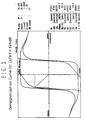
- This material is disadvantageous in the point that the coercive force is low, as seen from the demagnetization curve A of Fig. 1, in which the magnetic flux density decreases in proportion to the magnetic field strength. With such a magnetic material, a sufficient conversion efficiency cannot be achieved.
- the BH max value is high and the permeance coefficient is large, it means in itself that there is preserved a large amount of energy convertible into an electric energy or into a mechanical energy.
- a magnetic material has a high BH max value combined with a large permeance coefficient, its magnetization becomes more difficult and a considerable amount of energy will be consumed for the magnetization, so that it can be assumed that a magnet with a high BH max value and a large permeance coefficient possesses in itself an amount of magnetic energy corresponding to that required for its magnetization.
- An object of the present invention is to provide a power-generating electric motor of very high efficiency using a high BH max permanent magnet in a part of the permanent magnet of the rotor, which can afford to take out an electric power excessively and effectively.
- the present invention aims at a power-generating electric motor which can permit a long-lasting self-running by only supplying it with a starting power input and which realizes an efficient storage of electric power, by employing a special permanent magnet having a BH max value of at least 50 MGOe, preferably at least 100 MGOe, and a permeance coefficient of 1.0 to 4.0, preferably 2.5 to 3.5, in a form of, for example, a duplex structure with an inner layer magnet of Co-Fe-Y and an outer layer magnet of Fe-Nd-B.
- a special permanent magnet having a BH max value of at least 50 MGOe, preferably at least 100 MGOe, and a permeance coefficient of 1.0 to 4.0, preferably 2.5 to 3.5, in a form of, for example, a duplex structure with an inner layer magnet of Co-Fe-Y and an outer layer magnet of Fe-Nd-B.
- a very efficient power-generating electric motor permitting generation of an electric power which comprises a rotor of a permanent magnet; an armature arranged coaxially with the rotor with an air gap interposed therebetween and including a suitable number of field cores provided each with a field coil; and a brushless control circuit, by making use of a high BH max permanent magnet mentioned above, characterized in that the high BH max permanent magnet is disposed inside each magnet pole of the rotor so as to extend in the axial direction of the rotor and that an induction coil for power generation is arranged together with the field coil of the rotor.
- Fig. 1 is a graph showing the demagnetization curve for a conventional magnet material.
- Fig. 2 is a graph showing the demagnetization curve for a high BH max permanent magnet, according to the present invention.
- Fig. 3 shows an embodiment of the power-generating electric motor according to the present invention in an axial section.
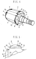
- Fig. 4 is a perspective view of the rotor of the motor of Fig. 3.
- Fig. 5 shows the rotor of Fig. 4 in a partial enlarged front view.
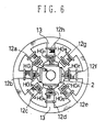
- Fig. 6 shows an embodiment of arrangement of the brushless control circuit in the motor according to the present invention.
- Fig. 7 shows an embodiment of construction of the brushless control circuit.
- Fig. 8 is a wiring chart of the induction coil in which the induction coil is connected parallel with a variable condenser.
- Fig. 9 is a graph showing the relationship between the motor efficiency and the rate of revolution of the rotor in which the induction coil circuit is out of tuning (solid curve) or tuned at a rotor revolution rate of 800 r.p.m. with the variable condenser (dotted curve).
- the rotor of a permanent magnet is made of a multilayered iron core composed of a rotary shaft and a magnetic material mounted on the shaft.
- the magnetic material may have a BH max value within the usual range.
- the number of magnet poles of the rotor are not restricted specifically and it may be in a 2-, 4- or 6-polar arrangement.
- the rotor is designed in a form of a cylinder, wherein the entire circumference of the rotor may be in a uniform acurate curve, while it is preferable to design the rotor in a form in which each magnetic pole protrudes outwards in a form of a ridge.
- a cut-off groove or canal extending in the axial direction of the rotor is provided for receiving a correspondingly shaped high BH max permanent magnet.
- the high BH max permanent magnet should have a BH max value of at least 50 MGOe, preferable at least 100 MGOe and a permeance coefficient of 1.0 to 4.0, preferably 2.5 to 3.5.
- An embodiment of the magnet which satisfies the above condition is constructed, as mentioned previously, by combining an inner layer magnet of Co-Fe-Y with an outer layer magnet of Fe-Ne-B, while other magnets and magnet combinations may also be employed therefor so long as the above condition is satisfied.
- the electric motor according to the present invention is characterized in that a high BH max permanent magnet is used as a part of the iron core of the rotor without deteriorating the motor efficiency.
- the polarity of the high BH max permanent magnet coincides with that of the ridged pole. While there is no limitation in the configuration of the high BH max magnet, it takes preferably a flat form. Here, it is preferable that the flat high BH max magnet is disposed inside the base portion of the ridge of the rotor magnet pole to extend within a cut-off canal almost over the entire width of the ridge with only a small uncutted rest or margin at each side end of the cut-off canal.
- the outer circumference of the ridge of the magnet pole may be shaped in a uniform arc surface, while it is preferable to cut a part of one side thereof into a plane surface.
- a stationary armature Surrounding the ridged magnet poles of the rotor, a stationary armature having a suitable number of field cores each provided with a field coil is disposed coaxially with the rotor with an air gap therebetween. It is preferable that each field core has a cut-off pierced canal in parallel to the axis of the rotor for receiving therein a high BH max permanent magnet.
- the power-generating motor according to the present invention has a brushless control circuit.
- a brushless control circuit every control mechanism without employing any brush is included, wherein an MR element, Hall-element, lead switch, magnetic diode, magnetic transistor or so on is used as a magnetic sensor, of which output is used for controlling the excitation of the field coil to rotate the rotor.
- the motor according to the present invention is characterized in that a more energy generation is attained by the use of the high BH max permanent magnet and a part of this energy is taken out as an electric energy.
- an induction coil for taking out the electric energy is arranged together with each field coil of the armature. It is preferable to dispose the induction coil at a position as near as possible to the field coil.
- the arrangement can be used as a motor as such.
- the induction coil with a condenser in parallel thereto, which causes tuning of the coil circuit to the frequency of the current generated at a lower revolution rate of the rotor, such as 500 - 800 r.p.m., whereby an electric power can be taken out effectively even at a lower revolution rate.
- a condenser in parallel thereto, which causes tuning of the coil circuit to the frequency of the current generated at a lower revolution rate of the rotor, such as 500 - 800 r.p.m., whereby an electric power can be taken out effectively even at a lower revolution rate.
- the motor according to the present invention operates in such a manner that a voluntary magnet pole of the rotor is caused to be attracted to a field core at certain position by energizing the field coil therefor, while detecting the passage of the magnet pole of the rotor by the field core using a magnetic sensor, the output signal of which is supplied to a control circuit to cause excitation of the next field coil and, at the same time, the deactivation of the preceding field coil.
- the rotor is rotated and corresponding mechanical energy is taken out from its rotary shaft.
- an induction current is generated in the induction coil when a magnetic pole of the rotor passes by the coil, which can be taken out as an electric power.
- a high BH max permanent magnet having a BH max value at least 50 MGOe, preferably at least 100 MGOe is mounted at each magnet pole of the rotor.
- the magnet flux density of the high BH max permanent magnet is so high that the induction energy generated upon passage of the induction coil through the magnet flux is vary large and, therefore, the rotor continues to be driven by the electric energy which is taken out of the induction coil and stored in the magnet, once a starting power input has been supplied.
- the power-generating motor includes a housing 1 and a rotor 2 composed of a rotary shaft 3 and an iron core 4.
- the iron core 4 consists of a permanent magnet with its magnet poles being formed each as a ridge 5, of which outer circumference has an arc surface 6 and a plane surface 7.
- a flat high BH max permanent magnet 8 is inserted in the cut-off canal 9 extending axially inside the base portion of each ridge 5 of the iron core of the rotor 2.
- This high BH max permanent magnet had a BH max value of 144.7 MGOe and a permeance coefficient of 3 and was formed in a duplex structure composed of an inner layer magnet of Co-Fe-Y and an outer layer magnet of Fe-Nd-B.
- the cut-off canal 9 receives the flat permanent magnet 8 and is formed extending almost over the entire width of the ridge 5 with only a small uncutted margin 10 at each side end.
- An armature 11 comprising a suitable number of field cores 13 each provided with a field coil 12 is arranged coaxially with the rotor 2.
- a flat high BH max permanent magnet 14 is insertedly disposed, as in the iron core 4 of the rotor.
- An induction coil 15 is arranged adjacent each of the field coils 12 and is excited upon the rotation of the rotor 2.
- Figs. 6 and 7 show the mechanical structure and the arrangement of the brushless control circuit, respectively, wherein each of the field coils 12a to 12h is provided with a Hall-element of HG1 to HG8.
- the Hall-element HG1 will generate an output signal, which causes the potential of the base of the transistor Tr1 to decrease to thereby excite the field coil 12a to cause the iron core 13a to assume as S-pole which attracts the magnet pole N1 of the rotor 2 to rotate it to a position opposing the field coil 12a.
- the base potential of the transistor TR1 is faded off by the extinction of the excitation current in the field coil 12a due to the moving away from the magnet pole N1, whereby the field core 13 becomes inactive towards the magnet pole N1.
- the induction coil 15 disposed adjacent the field coil 12 of the armature 11 is excited upon the rotation of the rotor 2 to generate an electric power.
- Fig. 8 shows the case in which a variable capacity condenser 16 is inserted in the field coil circuit in parallel connection with the field coil 15.
- Fig. 9 is a graph showing the relationship between the motor efficiency and the revolution rate of the rotor when the field coil circuit is tuned to an induction current frequency at a revolution rate of the rotor 2 of about 800 r.p.m., in which the dotted curve corresponds to the case where the condenser 16 is omitted and the solid curve corresponds to the case where the tuning condenser 16 is inserted.
- the driving of the motor and the storage of the electric power continued surprisigly for a period as long as one month, by supplying the motor only with the starting power input.
Landscapes
- Engineering & Computer Science (AREA)
- Power Engineering (AREA)
- Permanent Magnet Type Synchronous Machine (AREA)
- Permanent Field Magnets Of Synchronous Machinery (AREA)
- Brushless Motors (AREA)
- Control Of Eletrric Generators (AREA)
- Control Of Motors That Do Not Use Commutators (AREA)
- Lock And Its Accessories (AREA)
- Power Steering Mechanism (AREA)
Applications Claiming Priority (3)
| Application Number | Priority Date | Filing Date | Title |
|---|---|---|---|
| JP7274951A JPH0993996A (ja) | 1995-09-28 | 1995-09-28 | 発電電動機 |
| JP274951/95 | 1995-09-28 | ||
| PCT/JP1996/001624 WO1997012435A1 (en) | 1995-09-28 | 1996-06-13 | Generator/motor |
Publications (2)
| Publication Number | Publication Date |
|---|---|
| EP0806832A1 true EP0806832A1 (de) | 1997-11-12 |
| EP0806832A4 EP0806832A4 (de) | 1998-12-23 |
Family
ID=17548839
Family Applications (1)
| Application Number | Title | Priority Date | Filing Date |
|---|---|---|---|
| EP96917680A Withdrawn EP0806832A4 (de) | 1995-09-28 | 1996-06-13 | Elektrischer Motor zur Leistungserzeugung |
Country Status (11)
| Country | Link |
|---|---|
| US (1) | US5861693A (de) |
| EP (1) | EP0806832A4 (de) |
| JP (1) | JPH0993996A (de) |
| KR (1) | KR980700721A (de) |
| CN (1) | CN1167547A (de) |
| AU (1) | AU703971B2 (de) |
| BR (1) | BR9606643A (de) |
| CA (1) | CA2164745C (de) |
| NZ (1) | NZ309882A (de) |
| TW (1) | TW431051B (de) |
| WO (1) | WO1997012435A1 (de) |
Cited By (3)
| Publication number | Priority date | Publication date | Assignee | Title |
|---|---|---|---|---|
| EP1231703A3 (de) * | 2001-01-17 | 2003-11-19 | Gerd Schlüter | Unipolar-Maschine |
| SG120165A1 (en) * | 2004-02-25 | 2006-03-28 | Minato Kohei | Magnetic rotating motor generator |
| EP1850452A4 (de) * | 2005-02-09 | 2016-11-02 | Daikin Ind Ltd | Kern, rotor, motor und kompressor |
Families Citing this family (26)
| Publication number | Priority date | Publication date | Assignee | Title |
|---|---|---|---|---|
| EP0823771B1 (de) | 1996-02-23 | 2006-04-26 | Matsushita Electric Industrial Co., Ltd. | Motor |
| US6271614B1 (en) | 1998-11-20 | 2001-08-07 | Christopher J. Arnold | Pulsed plasma drive electromagnetic motor generator |
| FR2797533B1 (fr) * | 1999-08-13 | 2003-04-11 | Alain Delaite | Machine electrique tournante a courant alternatif |
| JP3740984B2 (ja) * | 2000-02-10 | 2006-02-01 | 日産自動車株式会社 | 電動機の磁極位置検出装置 |
| JP2002051534A (ja) * | 2000-08-03 | 2002-02-15 | Yoshiaki Takahashi | 家庭用発電システム |
| JP2002051535A (ja) * | 2000-08-03 | 2002-02-15 | Yoshiaki Takahashi | スクーターの電動駆動システム |
| KR20020052923A (ko) * | 2000-12-26 | 2002-07-04 | 박병순 | 교류 전동 발전기 |
| KR20030010370A (ko) * | 2001-07-26 | 2003-02-05 | 박병순 | 교류 전동 발전기 |
| KR20030015098A (ko) * | 2001-08-14 | 2003-02-20 | 박병순 | 초저압 교류 전동 발전기 |
| KR20030017956A (ko) * | 2001-08-25 | 2003-03-04 | 박병순 | 저압 교류 전동 발전기 |
| TW577658U (en) * | 2001-09-10 | 2004-02-21 | Adlee Powertronic Co Ltd | Rotor structure for a motor having built-in type permanebt magnet |
| KR20020075831A (ko) * | 2002-08-09 | 2002-10-07 | 최봉호 | 축전지(1)에 의해 발전된 전기의 일부분을 회전용코일(7)의 전원으로 사용하는 장치 |
| US6946766B2 (en) * | 2002-08-28 | 2005-09-20 | Emerson Electric Co. | Permanent magnet machine |
| US6727621B1 (en) | 2003-04-22 | 2004-04-27 | Northland/Scott Fetzer Company | Motor-based electrical power supply |
| EP2025050A2 (de) * | 2006-05-10 | 2009-02-18 | Jones, Robert, M. | Elektrische maschine mit segmentiertem stator |
| US7385328B2 (en) * | 2006-05-23 | 2008-06-10 | Reliance Electric Technologies, Llc | Cogging reduction in permanent magnet machines |
| GB0618729D0 (en) * | 2006-09-22 | 2006-11-01 | Hobby Roger B | Flux impulse motor |
| US7808143B2 (en) * | 2007-10-24 | 2010-10-05 | Rechi Precision Co., Ltd. | Permanent magnet motor |
| JP5380900B2 (ja) * | 2008-05-08 | 2014-01-08 | ダイキン工業株式会社 | 界磁子 |
| CN102428630B (zh) * | 2009-04-03 | 2014-04-02 | 罗伯特·M·琼斯 | 包覆模制的液体冷却三堆叠马达 |
| GB2462940B8 (en) * | 2009-09-03 | 2012-03-28 | Protean Holdings Corp | Electric motor and electric generator. |
| CN102447363A (zh) * | 2010-09-30 | 2012-05-09 | 艾默生电气公司 | 铝缠绕直接起动无刷永磁电动机 |
| JP6029598B2 (ja) * | 2012-01-31 | 2016-11-24 | 三菱電機株式会社 | ポンプ及び冷凍サイクル装置並びにポンプの製造方法 |
| CN106487131A (zh) * | 2015-08-28 | 2017-03-08 | 邓崇云 | 一种纳米高强磁能发电机及磁能发电系统 |
| GB2572350B (en) * | 2018-03-27 | 2023-01-25 | Hitachi Rail Ltd | An electromechanical generator for converting mechanical vibrational energy into electrical energy |
| CN112985877A (zh) * | 2021-02-04 | 2021-06-18 | 山东省地质矿产勘查开发局第四地质大队(山东省第四地质矿产勘查院) | 一种地质勘探用岩矿石标本参数测量装置 |
Family Cites Families (16)
| Publication number | Priority date | Publication date | Assignee | Title |
|---|---|---|---|---|
| US4237394A (en) * | 1977-05-23 | 1980-12-02 | Canon Kabushiki Kaisha | Frequency generator and miniature motor provided with the same |
| US4237395A (en) * | 1978-10-30 | 1980-12-02 | Loudermilk Billy E | Electric dynamotor |
| JPS56105605A (en) * | 1980-01-28 | 1981-08-22 | Hitachi Metals Ltd | Oxide permanent magnet |
| WO1983000955A1 (en) * | 1981-08-28 | 1983-03-17 | Iwaki, Yoshiyuki; | Generator for vehicle |
| JPS60131054A (ja) * | 1983-12-20 | 1985-07-12 | Nippon Denso Co Ltd | 内燃機関無接点点火装置用多極磁石発電機 |
| BG39783A1 (en) * | 1984-05-08 | 1986-08-15 | Popov | Rotor with permanent magnets for electric machine |
| US4720662A (en) * | 1986-06-20 | 1988-01-19 | Lanser Leslie V | Motor having alternator coils |
| US5006045A (en) * | 1987-12-24 | 1991-04-09 | Seiko Epson Corporation | Scroll compressor with reverse rotation speed limiter |
| JP3142002B2 (ja) * | 1990-07-12 | 2001-03-07 | セイコーエプソン株式会社 | 永久磁石回転子 |
| JP2615779B2 (ja) * | 1988-03-14 | 1997-06-04 | トヨタ自動車株式会社 | 回転界磁形モータ |
| US4942322A (en) * | 1988-05-27 | 1990-07-17 | Allied-Signal Inc. | Permanent magnet rotor with bonded sheath |
| WO1990009695A1 (de) * | 1989-02-17 | 1990-08-23 | Europe Patent Limited | Vorrichtung mit mehrphasiger last, statischem umrichter und drosselspulen |
| US5114502A (en) * | 1989-06-13 | 1992-05-19 | Sps Technologies, Inc. | Magnetic materials and process for producing the same |
| JP3164811B2 (ja) * | 1990-04-27 | 2001-05-14 | 松下電器産業株式会社 | 等方性永久磁石の製造方法 |
| EP0552365B1 (de) * | 1990-10-12 | 1996-11-06 | Seiko Epson Corporation | Verfahren zum schutz der magnete eines permanentmagnetischen rotors gegen korrosive stoffe |
| JPH05236688A (ja) * | 1992-02-25 | 1993-09-10 | Toshiba Corp | 永久磁石形モータ |
-
1995
- 1995-09-28 JP JP7274951A patent/JPH0993996A/ja active Pending
- 1995-11-17 US US08/559,938 patent/US5861693A/en not_active Expired - Fee Related
- 1995-12-08 CA CA002164745A patent/CA2164745C/en not_active Expired - Fee Related
-
1996
- 1996-06-13 EP EP96917680A patent/EP0806832A4/de not_active Withdrawn
- 1996-06-13 KR KR1019970703560A patent/KR980700721A/ko not_active Ceased
- 1996-06-13 BR BR9606643-1A patent/BR9606643A/pt unknown
- 1996-06-13 WO PCT/JP1996/001624 patent/WO1997012435A1/ja not_active Ceased
- 1996-06-13 CN CN96191181A patent/CN1167547A/zh active Pending
- 1996-06-13 NZ NZ309882A patent/NZ309882A/xx unknown
- 1996-06-13 AU AU60163/96A patent/AU703971B2/en not_active Ceased
- 1996-09-24 TW TW085111657A patent/TW431051B/zh not_active IP Right Cessation
Cited By (4)
| Publication number | Priority date | Publication date | Assignee | Title |
|---|---|---|---|---|
| EP1231703A3 (de) * | 2001-01-17 | 2003-11-19 | Gerd Schlüter | Unipolar-Maschine |
| SG120165A1 (en) * | 2004-02-25 | 2006-03-28 | Minato Kohei | Magnetic rotating motor generator |
| US7148596B2 (en) | 2004-02-25 | 2006-12-12 | Kohei Minato | Magnetic rotating motor generator |
| EP1850452A4 (de) * | 2005-02-09 | 2016-11-02 | Daikin Ind Ltd | Kern, rotor, motor und kompressor |
Also Published As
| Publication number | Publication date |
|---|---|
| BR9606643A (pt) | 1999-11-30 |
| TW431051B (en) | 2001-04-21 |
| AU703971B2 (en) | 1999-04-01 |
| CA2164745C (en) | 2001-02-20 |
| WO1997012435A1 (en) | 1997-04-03 |
| US5861693A (en) | 1999-01-19 |
| CA2164745A1 (en) | 1997-03-29 |
| CN1167547A (zh) | 1997-12-10 |
| EP0806832A4 (de) | 1998-12-23 |
| NZ309882A (en) | 1999-01-28 |
| JPH0993996A (ja) | 1997-04-04 |
| KR980700721A (ko) | 1998-03-30 |
| AU6016396A (en) | 1997-04-17 |
Similar Documents
| Publication | Publication Date | Title |
|---|---|---|
| US5861693A (en) | Power-generating electric motor | |
| US5041749A (en) | High speed, high power, single phase brushless DC motor | |
| US5465019A (en) | High-efficiency, low-noise electronically commutated motor having improved starting capability | |
| US5081388A (en) | Magnetic induction motor | |
| US5852335A (en) | Stator structure for rotary electric machine | |
| EP0048966B1 (de) | Feldpol-Struktur eines Gleichstrommotors | |
| CA2101662A1 (en) | Permanent Magnet Brushless Torque Actuator | |
| JP4383058B2 (ja) | リラクタンスモータ | |
| JP5280261B2 (ja) | リラクタンスモータ | |
| JP3059160B2 (ja) | ブラシレス直流電動機 | |
| US4794291A (en) | Permanent magnet field DC machine | |
| JP3268152B2 (ja) | 永久磁石界磁方式回転電機 | |
| US4728830A (en) | Electric motor with magnetic enhancement | |
| EP1182766A4 (de) | BüRSTENLOSER MOTOR | |
| US6437477B1 (en) | Hybrid electrical machine with axial flux magnet | |
| US5200729A (en) | Permanent magnet and magnetization apparatus for producing the permanent magnet | |
| CA1176699A (en) | Dc motor windings commutated by magnetically controllable electronic switches | |
| US5965967A (en) | Rotor for an electrical machine | |
| JP2001069738A (ja) | 外周対向形モータ | |
| JP4628527B2 (ja) | Dcモータ | |
| JPH0787685B2 (ja) | 永久磁石界磁式直流回転電機 | |
| JPH089610A (ja) | 永久磁石式回転電機 | |
| US6995490B2 (en) | Flux modifier for a permanent magnet brush-type motor using wound field coils combined with permanent magnets | |
| KR100451418B1 (ko) | 이중고정자구조의 직류전동기 | |
| JPS60200757A (ja) | ハイブリツド形リニヤパルスモ−タ |
Legal Events
| Date | Code | Title | Description |
|---|---|---|---|
| PUAI | Public reference made under article 153(3) epc to a published international application that has entered the european phase |
Free format text: ORIGINAL CODE: 0009012 |
|
| 17P | Request for examination filed |
Effective date: 19970627 |
|
| AK | Designated contracting states |
Kind code of ref document: A1 Designated state(s): BE DE ES FR GB IT LU NL |
|
| A4 | Supplementary search report drawn up and despatched | ||
| AK | Designated contracting states |
Kind code of ref document: A4 Designated state(s): BE DE ES FR GB IT LU NL |
|
| 17Q | First examination report despatched |
Effective date: 20010912 |
|
| STAA | Information on the status of an ep patent application or granted ep patent |
Free format text: STATUS: THE APPLICATION IS DEEMED TO BE WITHDRAWN |
|
| 18D | Application deemed to be withdrawn |
Effective date: 20030404 |