EP0806849B1 - Circuit pour le contrôle du bon fonctionnement de systèmes de réception mobiles - Google Patents
Circuit pour le contrôle du bon fonctionnement de systèmes de réception mobiles Download PDFInfo
- Publication number
- EP0806849B1 EP0806849B1 EP97106625A EP97106625A EP0806849B1 EP 0806849 B1 EP0806849 B1 EP 0806849B1 EP 97106625 A EP97106625 A EP 97106625A EP 97106625 A EP97106625 A EP 97106625A EP 0806849 B1 EP0806849 B1 EP 0806849B1
- Authority
- EP
- European Patent Office
- Prior art keywords
- signal
- frequency
- receiving system
- superheterodyne receiver
- aerial
- Prior art date
- Legal status (The legal status is an assumption and is not a legal conclusion. Google has not performed a legal analysis and makes no representation as to the accuracy of the status listed.)
- Expired - Lifetime
Links
Images
Classifications
-
- H—ELECTRICITY
- H04—ELECTRIC COMMUNICATION TECHNIQUE
- H04B—TRANSMISSION
- H04B5/00—Near-field transmission systems, e.g. inductive or capacitive transmission systems
- H04B5/70—Near-field transmission systems, e.g. inductive or capacitive transmission systems specially adapted for specific purposes
- H04B5/73—Near-field transmission systems, e.g. inductive or capacitive transmission systems specially adapted for specific purposes for taking measurements, e.g. using sensing coils
-
- H—ELECTRICITY
- H04—ELECTRIC COMMUNICATION TECHNIQUE
- H04B—TRANSMISSION
- H04B7/00—Radio transmission systems, i.e. using radiation field
- H04B7/02—Diversity systems; Multi-antenna system, i.e. transmission or reception using multiple antennas
- H04B7/04—Diversity systems; Multi-antenna system, i.e. transmission or reception using multiple antennas using two or more spaced independent antennas
- H04B7/08—Diversity systems; Multi-antenna system, i.e. transmission or reception using multiple antennas using two or more spaced independent antennas at the receiving station
- H04B7/0802—Diversity systems; Multi-antenna system, i.e. transmission or reception using multiple antennas using two or more spaced independent antennas at the receiving station using antenna selection
Definitions
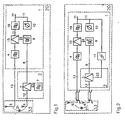
- the invention relates to a mobile receiving system, comprising at least one receiving antenna, which is connected to a heterodyne receiver, which is provided with Spiegelfrequenzndrükkung and with a measuring device for detecting the reception level, high frequency.
- image rejection 4 By forcibly present in the heterodyne receiver image rejection 4 to avoid the image frequency reception and the image frequency forcibly generated in the frequency converter 3 image frequency is suppressed.
- the received signal 13 is converted by means of the oscillator signal 8 in a mixer 15 to the intermediate frequency.
- the intermediate frequency signal 11 passes through the IF filter 19.
- the result of the functional check can either be recorded in a known manner by means of a measuring protocol or displayed on a display or acoustically or in a combination of the display options.
- the required for each test scope setpoints for the different frequency bases can be present in a memory of the mobile radio reception system or in a data memory outside the vehicle. In the latter case, a data line between the external data memory and the mobile receiving system is then required during the functional check.
- the frequency converter 3 is formed in its simplest embodiment by a series or parallel diode.
- a frequency converter 3 it is more advantageous to use a transistor as an additive or multiplicative mixing stage since the decoupling between input and output given by the transistor 12 allows the 12 to be tapped selectively in a simple manner via a switched-on resonant circuit. If a transistor push-pull mixing stage is used as the frequency converter 3, then the requirements for the amplitude constancy of the oscillator level supplied to the frequency converter 3 can be significantly reduced. The oscillator level respectively generated over the tuning range of the oscillator frequency must always be so great that the push-pull mixing stage operates in the switching mode.
- IF carrier oscillation 32 the intermediate frequency of the AM receiver, which is usually 455 kHz.
- IF carrier oscillation 32 typically 10.7 MHz is selected as IF carrier oscillation 32.
- the picture carrier intermediate frequency typically 38.9 MHz
- the intermediate audio frequency typically 33.4 MHz
- the IF carrier oscillation 32 can also be generated by using an amplifier with an extremely high amplifier, which is not driven at its input with a signal and at the output of which a resonant circuit is connected as an output filter whose natural frequency is the IF center frequency of the heterodyne receiver comes as close as possible, and that the signal filtered out of the self-noise of the amplifier forms the ZF carrier oscillation 32.
- Circuitry 2 coupling device 33 and heterodyne receiver can be arranged in close spatial proximity, whereby the required connection effort between the individual components remains extremely small.
- such an arrangement requires correspondingly large installation space, which are rarely available in modern automotive.
- the ZF carrier oscillation generating assembly 32 in the form of the IF oscillator 7 can be omitted if, by means of the circuit arrangement 2 according to the invention a self-excitation of the receiving system 20 is effected as shown in FIG. 2. Assuming that in the Function check first an unused receive channel is selected as the test frequency, a noise signal is received. When switching the mobile receiving system to the operation of the function check the present in the intermediate frequency amplifier section of the superimposed receiver intermediate frequency signal 11 is supplied with noise characteristic of a control device in the form of a Amplitudenbegrenzers 17, which is fed to the frequency converter 3 as limited in its amplitude ZF signal 22.
- This amplitude limiter 17 is always present for example in frequency-modulated received signals in the heterodyne receiver 1 in the form of a mostly integrated circuit. If the loop gain of the entire receiving system 20 chosen sufficiently large, so there is the state of self-excitation, since the phase condition for the self-excitation by the band-limiting effect of the IF selection for signals with noise characteristics by itself 'sets.
- the measuring device 10 for detecting the reception level should in this case detect the RMS (root mean square) value.
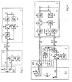
- Fig. 3 shows a receiving system according to the invention, in which the heterodyne receiver 1 is connected to the circuit arrangement 2 only via the antenna line 14.
- This RF connection line - usually designed as a coaxial line - forwards the receiving signal received from the receiving antenna 5 13 to the heterodyne receiver 1 and also performs the oscillator signal 8 of the heterodyne receiver 1 to the circuit arrangement 2. It is assumed that the input impedance of the filter for image rejection, the oscillator signal by appropriate dimensioning does not attenuate too much, on the other hand, the oscillator signal 8 at the output of the filter for image rejection is sufficiently suppressed. Both are possible by suitable dimensioning according to the prior art in a simple manner.
- the oscillator signal 8 is chosen dominantly, so that it exceeds the received signal 13 by at least one power of ten. This is achieved by suitably dimensioning the conversion gain or the mixed attenuation in the frequency converter 3 and by determining the coupling attenuation in the coupling device 33, the required level ratios are set.
- the RF output signal 12 is determined in its amplitude solely by the dominant oscillator signal 8 and by the amplitude of the IF carrier oscillation 32.
- the coupling device 33 consists of the receiving antenna 5, to which the RF output signal 12 of the frequency converter 3 is loosely coupled, for example via an electromagnetic wave.
- the RF output signal 12 is supplied to a transmission antenna 6, for example.
- This transmission antenna 6 can be mounted at a suitable location of the motor vehicle and emits the RF output signal 12 from.
- the receiving antenna 5 is designed as a glass antenna, it is particularly advantageous for the transmitting antenna 6 and the receiving antenna in to produce a screen-printing process on ESG panes or as inserted wires on laminated safety glass panes.
- the coupling attenuation of the coupling device 33 depends essentially on the spatial distance of the transmitting and receiving antenna and their mode of action. Capacitive antennas are preferably capacitive to excite, magnetically acting antennas preferably inductively couple.
- a coupling device 33 according to the invention can also consist in that the RF output signal 12 is supplied to the terminal of the receiving antenna via a small coupling capacity (for example a few pF in the VHF range).
- the RF output signal 12 can be fed to an RF line printed on the disk, in particular in the case of receiving antennas designed as glass antennas. Lying e.g. multiple receive antenna ports on one side of the wafer boundary, as may be the case for multi-antenna diversity systems, the RF line is e.g. in the form of an asymmetrical coplanar line also printed on this disc boundary and e.g. guided by branches over short distances along the antenna structures, so that the RF output signal is coupled substantially capacitively to the receiving antenna structures.
- the printed RF line is expediently terminated at its end with its characteristic impedance in order to obtain approximately constant current and voltage coating along the printed RF line.
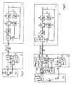
- the receiver-side changeover switch 26 can be replaced by a simple on / off switch, via which only the oscillator signal is switched to the IF signal in the function check mode. This can always be the case if the oscillator signal level is significantly greater than the IF level.
- the IF signal is conducted in diversity mode in addition to the received signal via only one RF connection line. Furthermore, in addition, a switching signal can be routed via the RF connection line, which switches from the diversity mode to individual antenna reception.
Landscapes
- Engineering & Computer Science (AREA)
- Computer Networks & Wireless Communication (AREA)
- Signal Processing (AREA)
- Radio Transmission System (AREA)
- Monitoring And Testing Of Transmission In General (AREA)
- Circuits Of Receivers In General (AREA)
Claims (13)
- Installation de réception mobile comportant au moins une antenne réceptrice qui comprend un récepteur hétérodyne relié à haute fréquence avec au moins une antenne réceptrice, et- avec un signal d'oscillateur,- avec un signal FI fixé pour le canal de réception choisi,- avec une inhibition de la fréquence-image (4) et- avec un dispositif de mesure (10) pour la détermination du niveau de réception,caractérisée en ce que :- il est prévu dans l'installation de réception (20) une disposition de circuit (2) avec un convertisseur de fréquence (3) et un oscillateur (7) variable dans la plage de fréquences de syntonisation concernée, dans lequel le signal d'oscillateur (8) du récepteur hétérodyne (1) est présent pendant le contrôle du fonctionnement,- l'oscillateur (7) produit une porteuse FI (32) d'amplitude constante dans le temps, dont la fréquence est aussi proche que possible de la fréquence moyenne en FI associée au canal de réception en question,- le convertisseur de fréquences (3) génère pendant le contrôle du fonctionnement, à partir du signal d'oscillateur (8) à fréquence variable du récepteur hétérodyne (1) et de la porteuse FI (32), un signal de sortie HF (12) dont la fréquence correspond à la fréquence de réception sur laquelle le récepteur hétérodyne (1) est syntonisé à ce moment,- il est prévu associé au circuit (2) et à l'antenne réceptrice (5) au nombre d'une au moins un dispositif de couplage (33) dans lequel le signal de sortie HF (12) est couplé de manière souple à l'antenne réceptrice (5) à une amplitude définie et transmis au récepteur hétérodyne (1) et au dispositif de mesure (10),- la détermination du niveau de réception dans le dispositif de mesure (10) permet de contrôler les fonctions de l'installation de réception (20).
- Installation de réception mobile selon la revendication 1, caractérisée en ce que la porteuse FI (32) est formée par auto-excitation de l'installation de réception (20) avec la disposition de circuit (2) de telle manière que le signal de fréquence intermédiaire (22) de la disposition de circuit (2) présent dans la partie d'amplificateur FI du récepteur hétérodyne (1) et dont l'amplitude est limitée est amené au convertisseur de fréquence (3) qui y est contenu, et l'amplification dans la boucle est suffisamment grande pour que l'état d'auto-excitation soit présent.
- Installation de réception mobile avec un récepteur hétérodyne (1) éloigné dans l'espace de l'antenne réceptrice (5) au nombre d'une au moins et relié à elle par une ligne de communication HF (14) selon l'une des revendications 1 et 2, caractérisée en ce que la disposition de circuit (2) est contenue dans le récepteur hétérodyne (1).
- Installation de réception mobile avec un récepteur hétérodyne (1) séparé dans l'espace de l'antenne réceptrice (5) et relié à elle par une ligne de communication HF (14) selon l'une des revendications 1 et 2, caractérisée en ce que la disposition de circuit (2) est disposée à proximité de l'antenne réceptrice (5) et en ce que pendant le contrôle du fonctionnement, le signal d'oscillateur (8) du récepteur hétérodyne (1) et le signal de réception HF (13) sont tous deux acheminés par la ligne de communication HF (14).
- Installation de réception mobile selon l'une des revendications 1 à 4, caractérisée en ce que le dispositif de couplage (33) se compose d'une antenne émettrice (6) ou d'une petite capacité reliée à l'antenne réceptrice (5), qui est éventuellement connectée à une extrémité d'une autre ligne de communication HF (23), et en ce que le signal de sortie HF (12) du convertisseur de fréquence (3) est transmis de manière souple par le dispositif de couplage (33) à l'antenne réceptrice (5).
- Installation de réception mobile selon l'une des revendications 1 à 4, caractérisée en ce que le dispositif de couplage (33) se compose d'une ligne HF ouverte terminée à son extrémité, à laquelle est amené le signal de sortie HF (12), lequel signal de sortie HF (12) est couplé de façon capacitive ou inductive à l'antenne réceptrice (5) ou à son point de connexion.
- Installation de réception mobile selon l'une des revendications 5 et 6, caractérisée en ce que le dispositif de couplage (33) est réalisé à proximité de l'antenne réceptrice (5) par sérigraphie sur les vitres en verre trempé de sécurité ou sous la forme d'un fil ou de fils intégrés dans les vitres en verre feuilleté de sécurité.
- Installation de réception mobile selon l'une des revendications 1 à 7, caractérisée en ce que le contrôle du fonctionnement est réalisé dans une lacune d'émission qui est déterminée par un cycle de recherche du récepteur hétérodyne par la détermination du niveau de réception en fonction de la fréquence de réception.
- Installation de réception mobile selon l'une des revendications 1 à 8, caractérisée en ce que :- il est prévu à l'entrée du récepteur hétérodyne (1) un aiguillage de signaux (16) du côté du récepteur, auquel sont transmis le signal d'oscillateur (8) du récepteur hétérodyne (1) et soit le signal FI (11), soit le signal FI d'amplitude limitée (22), et en ce que le signal de réception HF (13) est alors transmis en boucle au récepteur hétérodyne (1),- le signal de réception HF (13) ainsi que le signal d'oscillateur (8) et soit le signal FI (11), soit le signal FI d'amplitude limitée (22) sont transmis sur la ligne de communication HF (14), et- il est prévu du côté de la disposition de circuit un aiguillage de signaux (18) sur lequel sont captés le signal d'oscillateur (8) et soit le signal FI (11), soit le signal FI d'amplitude limitée (22), et le signal de réception HF (13) est alors transmis en boucle de l'antenne réceptrice (5) au nombre d'une au moins à la ligne de communication HF (14), et- en ce que les aiguillages de signaux sont réalisés de telle manière que les signaux ne s'influencent pas réciproquement.
- Installation de réception mobile selon la revendication 9, caractérisée en ce que l'un au moins des aiguillages de signaux est directionnel.
- Installation de réception mobile selon la revendication 9, caractérisée en ce que l'un au moins des aiguillages de signaux est sélectif en fréquence.
- Installation de réception mobile selon la revendication 9, caractérisée en ce que l'un au moins des aiguillages de signaux est conçu pour être directionnel par des coupleurs directionnels et pour être également sélectif en fréquence en vue de favoriser les propriétés de sélection.
- Installation de réception mobile selon l'une des revendications 1 à 12 avec une fonction de diversité d'antennes à balayage, dans laquelle il n'est prévu qu'une ligne de communication HF (14) coaxiale entre le processeur de diversité (30) et le récepteur hétérodyne (1), qui transmet au moyen d'un aiguillage de signaux (18) dans le processeur de diversité et d'un aiguillage de signaux (16) dans le récepteur hétérodyne un signal de commutation (29) et le signal FI (11) du récepteur hétérodyne (1) au processeur de diversité (30), caractérisée en ce que lors d'un contrôle du fonctionnement, outre le signal FI, le signal d'oscillateur (8) du récepteur hétérodyne est transmis par la ligne de communication (14) coaxiale et le niveau de l'oscillateur et choisi de telle sorte que si des mesures de sélection existent déjà dans les aiguillages de signaux, aucune autre mesure n'est nécessaire.
Applications Claiming Priority (2)
| Application Number | Priority Date | Filing Date | Title |
|---|---|---|---|
| DE19618333 | 1996-05-07 | ||
| DE19618333A DE19618333A1 (de) | 1996-05-07 | 1996-05-07 | Schaltungsanordnung zur Funktionsprüfung mobiler Rundfunkempfangsanlagen |
Publications (3)
| Publication Number | Publication Date |
|---|---|
| EP0806849A2 EP0806849A2 (fr) | 1997-11-12 |
| EP0806849A3 EP0806849A3 (fr) | 2000-08-02 |
| EP0806849B1 true EP0806849B1 (fr) | 2007-05-23 |
Family
ID=7793609
Family Applications (1)
| Application Number | Title | Priority Date | Filing Date |
|---|---|---|---|
| EP97106625A Expired - Lifetime EP0806849B1 (fr) | 1996-05-07 | 1997-04-22 | Circuit pour le contrôle du bon fonctionnement de systèmes de réception mobiles |
Country Status (3)
| Country | Link |
|---|---|
| US (1) | US6011962A (fr) |
| EP (1) | EP0806849B1 (fr) |
| DE (2) | DE19618333A1 (fr) |
Families Citing this family (59)
| Publication number | Priority date | Publication date | Assignee | Title |
|---|---|---|---|---|
| US6144852A (en) * | 1996-11-07 | 2000-11-07 | Lucent Technologies Inc. | Remote office administrative and maintenance system for cell sites in a wireless telecommunication network |
| DE19823523C1 (de) * | 1998-05-26 | 1999-08-19 | Siemens Ag | Anordnung zur Funktionsprüfung von Funkstationen eines Funk-Kommunikationssystems |
| JP4106136B2 (ja) * | 1998-09-04 | 2008-06-25 | 新潟精密株式会社 | 通信装置の計測方式 |
| DE19842075A1 (de) * | 1998-09-15 | 2000-03-16 | Joop A B Halbesma | Schaltungsanordnung und Verfahren zur Betriebsabrechnung von Hochfrequenzanlagen |
| DE19847887A1 (de) * | 1998-10-18 | 2000-04-20 | Heinz Lindenmeier | Scanning-Antennen-Diversity-System für Fahrzeuge |
| US6308064B1 (en) * | 1998-11-19 | 2001-10-23 | Telefonaktiebolaget Lm Ericsson (Publ) | Air interface based wireless telecommunication test system |
| DE19858465A1 (de) * | 1998-12-17 | 2000-06-21 | Heinz Lindenmeier | Scanning-Diversity-Antennensystem für Fahrzeuge |
| DE19930571B4 (de) | 1999-07-02 | 2010-04-29 | Delphi Delco Electronics Europe Gmbh | Diagnosevorrichtung für eine Mehrantennenanordnung |
| DE19931252C1 (de) | 1999-07-07 | 2001-03-29 | Bosch Gmbh Robert | Schaltungsanordnung und Verfahren zur Prüfung eines Rundfunkempfangssystems |
| US6236371B1 (en) * | 1999-07-26 | 2001-05-22 | Harris Corporation | System and method for testing antenna frequency response |
| JP3408481B2 (ja) * | 2000-02-02 | 2003-05-19 | エヌイーシーマイクロシステム株式会社 | 直交変調器および直交変調方法 |
| JP3631083B2 (ja) * | 2000-02-14 | 2005-03-23 | 三洋電機株式会社 | 無線基地局及び移動局 |
| DE10031005A1 (de) * | 2000-06-30 | 2002-01-17 | Schleifring Und Appbau Gmbh | Selbstdiagnostizierendes Übertragungssstem-Intelligenter Schleifring |
| US7050778B1 (en) * | 2000-09-18 | 2006-05-23 | Broadcom Corporation | Direct conversion turner |
| DE20019677U1 (de) | 2000-11-20 | 2001-02-15 | Hirschmann Electronics GmbH & Co. KG, 72654 Neckartenzlingen | Antennensystem |
| US6976075B2 (en) * | 2000-12-08 | 2005-12-13 | Clarinet Systems, Inc. | System uses communication interface for configuring a simplified single header packet received from a PDA into multiple headers packet before transmitting to destination device |
| JP2002208869A (ja) * | 2001-01-09 | 2002-07-26 | Sony Corp | マルチバンド無線信号送受信装置 |
| JP3540782B2 (ja) * | 2001-08-06 | 2004-07-07 | 三洋電機株式会社 | 無線基地装置、無線端末装置、移動体通信システム、および受信動作制御プログラム |
| EP1440539A4 (fr) | 2001-09-27 | 2009-08-26 | Broadcom Corp | Commande d'acces a un support a forte integration |
| EP1476764A1 (fr) * | 2002-02-22 | 2004-11-17 | DaimlerChrysler AG | Procede et dispositif pour controler au moins une antenne |
| US20040127161A1 (en) * | 2002-12-31 | 2004-07-01 | Motorola, Inc. | Mobile communication unit with self-diagnostic capability |
| KR100531619B1 (ko) * | 2003-04-10 | 2005-11-28 | 주식회사 케이티프리텔 | 수신전용 패스를 포함하는 통신 시스템의 수신감도를측정하는 장치 및 방법 |
| US20040230997A1 (en) * | 2003-05-13 | 2004-11-18 | Broadcom Corporation | Single-chip cable set-top box |
| US7336939B2 (en) * | 2003-05-21 | 2008-02-26 | Broadcom Corporation | Integrated tracking filters for direct conversion and low-IF single conversion broadband filters |
| US7702306B2 (en) * | 2003-08-28 | 2010-04-20 | Broadcom Corporation | Apparatus and method for local oscillator calibration in mixer circuits |
| US7894790B2 (en) * | 2004-04-02 | 2011-02-22 | Broadcom Corporation | Dual conversion receiver with reduced harmonic interference |
| US8578434B2 (en) * | 2004-05-21 | 2013-11-05 | Broadcom Corporation | Integrated cable modem |
| US8732788B2 (en) * | 2004-05-21 | 2014-05-20 | Broadcom Corporation | Integrated set-top box |
| EP1612965A3 (fr) * | 2004-07-01 | 2012-01-04 | NEC Corporation | Sélecteur d'antenne |
| US8239914B2 (en) * | 2004-07-22 | 2012-08-07 | Broadcom Corporation | Highly integrated single chip set-top box |
| US20060025171A1 (en) * | 2004-07-27 | 2006-02-02 | Dell Products L.P. | Information handling system capable of switching among multiple wireless radio architectures |
| US7444119B2 (en) * | 2004-11-30 | 2008-10-28 | Symbol Technologies, Inc. | Method for sharing antennas of a wireless device |
| KR100587791B1 (ko) * | 2004-12-08 | 2006-06-09 | 한국항공우주연구원 | 중간주파수 조절을 위한 주파수 송수신 장치 |
| DE102005039526A1 (de) * | 2005-08-18 | 2007-02-22 | Daimlerchrysler Ag | Verfahren und Diagnosevorrichtung zur selektiven Prüfung von Empfangsantennen in einem Mehrantennensystem |
| DE102006039357B4 (de) * | 2005-09-12 | 2018-06-28 | Heinz Lindenmeier | Antennendiversityanlage zum Funkempfang für Fahrzeuge |
| JP2007288257A (ja) * | 2006-04-12 | 2007-11-01 | Fujitsu Ten Ltd | 受信システム |
| US20070294738A1 (en) * | 2006-06-16 | 2007-12-20 | Broadcom Corporation | Single chip cable set-top box supporting DOCSIS set-top Gateway (DSG) protocol and high definition advanced video codec (HD AVC) decode |
| US7634236B2 (en) * | 2006-11-15 | 2009-12-15 | Northrop Grumman Corporation | Controlled signal-to-noise ratio generator circuit |
| DE102007017478A1 (de) * | 2007-04-13 | 2008-10-16 | Lindenmeier, Heinz, Prof. Dr. Ing. | Empfangsanlage mit einer Schaltungsanordnung zur Unterdrückung von Umschaltstörungen bei Antennendiversity |
| EP2037593A3 (fr) * | 2007-07-10 | 2016-10-12 | Delphi Delco Electronics Europe GmbH | Installation de diversité d'antennes pour la réception radio à bande relativement large dans des véhicules |
| DE102007039914A1 (de) * | 2007-08-01 | 2009-02-05 | Lindenmeier, Heinz, Prof. Dr. Ing. | Antennendiversityanlage mit zwei Antennen für den Funkempfang in Fahrzeugen |
| DE102008003532A1 (de) * | 2007-09-06 | 2009-03-12 | Lindenmeier, Heinz, Prof. Dr. Ing. | Antenne für den Satellitenempfang |
| PT2209221T (pt) * | 2009-01-19 | 2018-12-27 | Fuba Automotive Electronics Gmbh | Sistema de recepção para a soma de sinais de antena em fase |
| DE102009011542A1 (de) * | 2009-03-03 | 2010-09-09 | Heinz Prof. Dr.-Ing. Lindenmeier | Antenne für den Empfang zirkular in einer Drehrichtung der Polarisation ausgestrahlter Satellitenfunksignale |
| US20100306814A1 (en) * | 2009-05-26 | 2010-12-02 | Broadcom Corporation | Integrated Set-Top Box with Daisy-Chaining |
| DE102009023514A1 (de) * | 2009-05-30 | 2010-12-02 | Heinz Prof. Dr.-Ing. Lindenmeier | Antenne für zirkulare Polarisation mit einer leitenden Grundfläche |
| US9590733B2 (en) | 2009-07-24 | 2017-03-07 | Corning Optical Communications LLC | Location tracking using fiber optic array cables and related systems and methods |
| US8634766B2 (en) | 2010-02-16 | 2014-01-21 | Andrew Llc | Gain measurement and monitoring for wireless communication systems |
| WO2011123336A1 (fr) | 2010-03-31 | 2011-10-06 | Corning Cable Systems Llc | Services de localisation dans des composants et systèmes de communications distribués à base de fibres optiques et procédés connexes |
| US8570914B2 (en) | 2010-08-09 | 2013-10-29 | Corning Cable Systems Llc | Apparatuses, systems, and methods for determining location of a mobile device(s) in a distributed antenna system(s) |
| US9781553B2 (en) | 2012-04-24 | 2017-10-03 | Corning Optical Communications LLC | Location based services in a distributed communication system, and related components and methods |
| WO2013181247A1 (fr) | 2012-05-29 | 2013-12-05 | Corning Cable Systems Llc | Localisation au moyen d'ultrasons de dispositifs clients à complément de navigation par inertie dans des systèmes de communication distribués et dispositifs et procédés associés |
| US9647758B2 (en) | 2012-11-30 | 2017-05-09 | Corning Optical Communications Wireless Ltd | Cabling connectivity monitoring and verification |
| US9158864B2 (en) | 2012-12-21 | 2015-10-13 | Corning Optical Communications Wireless Ltd | Systems, methods, and devices for documenting a location of installed equipment |
| US9385810B2 (en) | 2013-09-30 | 2016-07-05 | Corning Optical Communications Wireless Ltd | Connection mapping in distributed communication systems |
| WO2015151086A1 (fr) | 2014-03-31 | 2015-10-08 | Corning Optical Communications Wireless Ltd. | Continuité de système d'antenne distribuée |
| US9648580B1 (en) | 2016-03-23 | 2017-05-09 | Corning Optical Communications Wireless Ltd | Identifying remote units in a wireless distribution system (WDS) based on assigned unique temporal delay patterns |
| US10560136B2 (en) | 2016-05-31 | 2020-02-11 | Corning Optical Communications LLC | Antenna continuity |
| CN115128361B (zh) * | 2022-06-30 | 2024-12-17 | 电子科技大学 | 超大动态范围脉冲场强测试系统及方法 |
Family Cites Families (10)
| Publication number | Priority date | Publication date | Assignee | Title |
|---|---|---|---|---|
| JPS5324714A (en) * | 1976-08-20 | 1978-03-07 | Alps Electric Co Ltd | Ssb transceiver |
| US4149122A (en) * | 1977-06-30 | 1979-04-10 | Cutler-Hammer, Inc. | Wideband tracking generator for harmonic mixing receivers |
| US4225969A (en) * | 1979-01-31 | 1980-09-30 | International Business Machines Corporation | Method and apparatus for testing a frequency synthesizer in an RF modem |
| JPS5621435A (en) * | 1979-07-31 | 1981-02-27 | Nissan Motor Co Ltd | Extrahigh frequency transmitting and receiving device |
| JPS58190731A (ja) * | 1982-04-30 | 1983-11-07 | Shimadzu Corp | パツシエンルンゲ形分光器 |
| US4776032A (en) * | 1985-05-15 | 1988-10-04 | Nippon Telegraph And Telephone Corporation | Repeater for a same frequency with spillover measurement |
| US5015973A (en) * | 1987-08-31 | 1991-05-14 | Oki Electric Industry Co., Ltd. | Duplexer with an isolating circuit on a dielectric plate |
| JPH063886B2 (ja) * | 1988-06-14 | 1994-01-12 | 富士通株式会社 | 折り返し試験機 |
| US4984293A (en) * | 1989-10-17 | 1991-01-08 | Rockwell International Corporation | Multi-channel microwave receiver having self-test capability |
| US5625889A (en) * | 1995-01-13 | 1997-04-29 | Hughes Electronics | RF sniffer module and method with a self-test circuit |
-
1996
- 1996-05-07 DE DE19618333A patent/DE19618333A1/de not_active Ceased
-
1997
- 1997-04-22 EP EP97106625A patent/EP0806849B1/fr not_active Expired - Lifetime
- 1997-04-22 DE DE59712846T patent/DE59712846D1/de not_active Expired - Lifetime
- 1997-05-07 US US08/852,561 patent/US6011962A/en not_active Expired - Lifetime
Non-Patent Citations (1)
| Title |
|---|
| None * |
Also Published As
| Publication number | Publication date |
|---|---|
| EP0806849A2 (fr) | 1997-11-12 |
| US6011962A (en) | 2000-01-04 |
| DE19618333A1 (de) | 1997-11-13 |
| DE59712846D1 (de) | 2007-07-05 |
| EP0806849A3 (fr) | 2000-08-02 |
Similar Documents
| Publication | Publication Date | Title |
|---|---|---|
| EP0806849B1 (fr) | Circuit pour le contrôle du bon fonctionnement de systèmes de réception mobiles | |
| DE4101629C3 (de) | Antennendiversity-Anlage mit mindestens zwei Antennen für den mobilen Empfang von Meter- und Dezimeterwellen | |
| DE69221355T2 (de) | Scheibenantennensystem für Kraftfahrzeug | |
| DE69735156T2 (de) | Multibandkommunikationsgerät | |
| DE3889328T2 (de) | Fernsehkanalschalter. | |
| DE3903262C2 (fr) | ||
| DE4396900C2 (de) | HF-Antennenschalter insbes. zum Umschalten zwischen einer ersten und zweiten Antenne | |
| DE69211330T2 (de) | Funksende- und -empfangsanordnung | |
| DE69331653T2 (de) | Hochfrequenzschaltung für ein TDMA System | |
| DE69631890T2 (de) | Tv/fm tuner für multimedia | |
| DE3311640C2 (fr) | ||
| EP0304611B1 (fr) | Montage de circuits pour la distribution de signaux d'antenne | |
| DE4204490A1 (de) | Schaltungsanordnung zur unterdrueckung von umschaltstoerungen bei antennendiversity | |
| DE69918606T2 (de) | Direktrundfunkübertragungssatellitenempfänger | |
| DE69222279T2 (de) | TDMA-TDD Sender-Empfänger | |
| DE2937913C3 (de) | Elektronische Schaltanordnung | |
| EP3987666A1 (fr) | Ensemble circuit servant à la transmission de signaux radio et procédé de fonctionnement d'un ensemble circuit | |
| DE60217165T2 (de) | Digitale-audio-rundfunk-v | |
| EP0597534A2 (fr) | Emetteur-récepteur radio | |
| DE4222309A1 (de) | Schaltungsanordnung zur Erkennung und Unterdrückung von Nachbarkanalstörungen | |
| EP1110317B1 (fr) | Appareil de reception radio | |
| DE69827922T2 (de) | Filter für ein Mobilfunktelefon | |
| DE69636633T2 (de) | Empfangsschaltung für ein tragbares Telefon | |
| DE60115572T2 (de) | Verfahren und Schaltung eines Multibandempfänger in einem Mobilfunktelefon | |
| DE10352290A1 (de) | Antennenverstärker |
Legal Events
| Date | Code | Title | Description |
|---|---|---|---|
| PUAI | Public reference made under article 153(3) epc to a published international application that has entered the european phase |
Free format text: ORIGINAL CODE: 0009012 |
|
| AK | Designated contracting states |
Kind code of ref document: A2 Designated state(s): DE ES FR GB IT SE |
|
| RAP1 | Party data changed (applicant data changed or rights of an application transferred) |
Owner name: FUBA AUTOMOTIVE GMBH |
|
| PUAL | Search report despatched |
Free format text: ORIGINAL CODE: 0009013 |
|
| RAP1 | Party data changed (applicant data changed or rights of an application transferred) |
Owner name: FUBA AUTOMOTIVE GMBH & CO. KG |
|
| AK | Designated contracting states |
Kind code of ref document: A3 Designated state(s): DE ES FR GB IT SE |
|
| 17P | Request for examination filed |
Effective date: 20000825 |
|
| 17Q | First examination report despatched |
Effective date: 20010314 |
|
| GRAP | Despatch of communication of intention to grant a patent |
Free format text: ORIGINAL CODE: EPIDOSNIGR1 |
|
| GRAS | Grant fee paid |
Free format text: ORIGINAL CODE: EPIDOSNIGR3 |
|
| GRAA | (expected) grant |
Free format text: ORIGINAL CODE: 0009210 |
|
| AK | Designated contracting states |
Kind code of ref document: B1 Designated state(s): DE ES FR GB IT SE |
|
| REG | Reference to a national code |
Ref country code: GB Ref legal event code: FG4D Free format text: NOT ENGLISH |
|
| REF | Corresponds to: |
Ref document number: 59712846 Country of ref document: DE Date of ref document: 20070705 Kind code of ref document: P |
|
| PG25 | Lapsed in a contracting state [announced via postgrant information from national office to epo] |
Ref country code: SE Free format text: LAPSE BECAUSE OF FAILURE TO SUBMIT A TRANSLATION OF THE DESCRIPTION OR TO PAY THE FEE WITHIN THE PRESCRIBED TIME-LIMIT Effective date: 20070823 |
|
| PG25 | Lapsed in a contracting state [announced via postgrant information from national office to epo] |
Ref country code: ES Free format text: LAPSE BECAUSE OF FAILURE TO SUBMIT A TRANSLATION OF THE DESCRIPTION OR TO PAY THE FEE WITHIN THE PRESCRIBED TIME-LIMIT Effective date: 20070903 |
|
| ET | Fr: translation filed | ||
| GBV | Gb: ep patent (uk) treated as always having been void in accordance with gb section 77(7)/1977 [no translation filed] |
Effective date: 20070523 |
|
| PLBE | No opposition filed within time limit |
Free format text: ORIGINAL CODE: 0009261 |
|
| STAA | Information on the status of an ep patent application or granted ep patent |
Free format text: STATUS: NO OPPOSITION FILED WITHIN TIME LIMIT |
|
| 26N | No opposition filed |
Effective date: 20080226 |
|
| PG25 | Lapsed in a contracting state [announced via postgrant information from national office to epo] |
Ref country code: GB Free format text: LAPSE BECAUSE OF FAILURE TO SUBMIT A TRANSLATION OF THE DESCRIPTION OR TO PAY THE FEE WITHIN THE PRESCRIBED TIME-LIMIT Effective date: 20070523 |
|
| REG | Reference to a national code |
Ref country code: FR Ref legal event code: TP |
|
| REG | Reference to a national code |
Ref country code: FR Ref legal event code: PLFP Year of fee payment: 19 |
|
| PGFP | Annual fee paid to national office [announced via postgrant information from national office to epo] |
Ref country code: DE Payment date: 20150429 Year of fee payment: 19 |
|
| PGFP | Annual fee paid to national office [announced via postgrant information from national office to epo] |
Ref country code: IT Payment date: 20150428 Year of fee payment: 19 Ref country code: FR Payment date: 20150417 Year of fee payment: 19 |
|
| REG | Reference to a national code |
Ref country code: DE Ref legal event code: R119 Ref document number: 59712846 Country of ref document: DE |
|
| REG | Reference to a national code |
Ref country code: FR Ref legal event code: ST Effective date: 20161230 |
|
| PG25 | Lapsed in a contracting state [announced via postgrant information from national office to epo] |
Ref country code: DE Free format text: LAPSE BECAUSE OF NON-PAYMENT OF DUE FEES Effective date: 20161101 Ref country code: FR Free format text: LAPSE BECAUSE OF NON-PAYMENT OF DUE FEES Effective date: 20160502 |
|
| PG25 | Lapsed in a contracting state [announced via postgrant information from national office to epo] |
Ref country code: IT Free format text: LAPSE BECAUSE OF NON-PAYMENT OF DUE FEES Effective date: 20160422 |