EP0806873A2 - Multiplex-Übertragungsverfahren und -system, und Audiogitterabsorptionsverfahren dafür - Google Patents
Multiplex-Übertragungsverfahren und -system, und Audiogitterabsorptionsverfahren dafür Download PDFInfo
- Publication number
- EP0806873A2 EP0806873A2 EP97107526A EP97107526A EP0806873A2 EP 0806873 A2 EP0806873 A2 EP 0806873A2 EP 97107526 A EP97107526 A EP 97107526A EP 97107526 A EP97107526 A EP 97107526A EP 0806873 A2 EP0806873 A2 EP 0806873A2
- Authority
- EP
- European Patent Office
- Prior art keywords
- frame
- multiplex
- length
- data
- retransmission
- Prior art date
- Legal status (The legal status is an assumption and is not a legal conclusion. Google has not performed a legal analysis and makes no representation as to the accuracy of the status listed.)
- Withdrawn
Links
Images


Classifications
-
- H—ELECTRICITY
- H04—ELECTRIC COMMUNICATION TECHNIQUE
- H04N—PICTORIAL COMMUNICATION, e.g. TELEVISION
- H04N19/00—Methods or arrangements for coding, decoding, compressing or decompressing digital video signals
- H04N19/85—Methods or arrangements for coding, decoding, compressing or decompressing digital video signals using pre-processing or post-processing specially adapted for video compression
- H04N19/89—Methods or arrangements for coding, decoding, compressing or decompressing digital video signals using pre-processing or post-processing specially adapted for video compression involving methods or arrangements for detection of transmission errors at the decoder
-
- H—ELECTRICITY
- H04—ELECTRIC COMMUNICATION TECHNIQUE
- H04N—PICTORIAL COMMUNICATION, e.g. TELEVISION
- H04N21/00—Selective content distribution, e.g. interactive television or video on demand [VOD]
- H04N21/20—Servers specifically adapted for the distribution of content, e.g. VOD servers; Operations thereof
- H04N21/23—Processing of content or additional data; Elementary server operations; Server middleware
- H04N21/236—Assembling of a multiplex stream, e.g. transport stream, by combining a video stream with other content or additional data, e.g. inserting a URL [Uniform Resource Locator] into a video stream, multiplexing software data into a video stream; Remultiplexing of multiplex streams; Insertion of stuffing bits into the multiplex stream, e.g. to obtain a constant bit-rate; Assembling of a packetised elementary stream
- H04N21/2368—Multiplexing of audio and video streams
-
- H—ELECTRICITY
- H04—ELECTRIC COMMUNICATION TECHNIQUE
- H04N—PICTORIAL COMMUNICATION, e.g. TELEVISION
- H04N21/00—Selective content distribution, e.g. interactive television or video on demand [VOD]
- H04N21/20—Servers specifically adapted for the distribution of content, e.g. VOD servers; Operations thereof
- H04N21/23—Processing of content or additional data; Elementary server operations; Server middleware
- H04N21/238—Interfacing the downstream path of the transmission network, e.g. adapting the transmission rate of a video stream to network bandwidth; Processing of multiplex streams
- H04N21/2383—Channel coding or modulation of digital bit-stream, e.g. QPSK modulation
-
- H—ELECTRICITY
- H04—ELECTRIC COMMUNICATION TECHNIQUE
- H04N—PICTORIAL COMMUNICATION, e.g. TELEVISION
- H04N21/00—Selective content distribution, e.g. interactive television or video on demand [VOD]
- H04N21/40—Client devices specifically adapted for the reception of or interaction with content, e.g. set-top-box [STB]; Operations thereof
- H04N21/43—Processing of content or additional data, e.g. demultiplexing additional data from a digital video stream; Elementary client operations, e.g. monitoring of home network or synchronising decoder's clock; Client middleware
- H04N21/434—Disassembling of a multiplex stream, e.g. demultiplexing audio and video streams, extraction of additional data from a video stream; Remultiplexing of multiplex streams; Extraction or processing of SI; Disassembling of packetised elementary stream
- H04N21/4341—Demultiplexing of audio and video streams
-
- H—ELECTRICITY
- H04—ELECTRIC COMMUNICATION TECHNIQUE
- H04N—PICTORIAL COMMUNICATION, e.g. TELEVISION
- H04N21/00—Selective content distribution, e.g. interactive television or video on demand [VOD]
- H04N21/40—Client devices specifically adapted for the reception of or interaction with content, e.g. set-top-box [STB]; Operations thereof
- H04N21/43—Processing of content or additional data, e.g. demultiplexing additional data from a digital video stream; Elementary client operations, e.g. monitoring of home network or synchronising decoder's clock; Client middleware
- H04N21/438—Interfacing the downstream path of the transmission network originating from a server, e.g. retrieving encoded video stream packets from an IP network
- H04N21/4382—Demodulation or channel decoding, e.g. QPSK demodulation
-
- H—ELECTRICITY
- H04—ELECTRIC COMMUNICATION TECHNIQUE
- H04N—PICTORIAL COMMUNICATION, e.g. TELEVISION
- H04N21/00—Selective content distribution, e.g. interactive television or video on demand [VOD]
- H04N21/60—Network structure or processes for video distribution between server and client or between remote clients; Control signalling between clients, server and network components; Transmission of management data between server and client, e.g. sending from server to client commands for recording incoming content stream; Communication details between server and client
- H04N21/63—Control signaling related to video distribution between client, server and network components; Network processes for video distribution between server and clients or between remote clients, e.g. transmitting basic layer and enhancement layers over different transmission paths, setting up a peer-to-peer communication via Internet between remote STB's; Communication protocols; Addressing
- H04N21/637—Control signals issued by the client directed to the server or network components
- H04N21/6375—Control signals issued by the client directed to the server or network components for requesting retransmission, e.g. of data packets lost or corrupted during transmission from server
Definitions
- the present invention relates to multiplex transmission methods and systems, and to audio jitter absorbing methods used therein, and more particularly to a method of multiplexing and transmitting low-bitrate-compressed audio data and video data and/or computer data and a method of absorbing audio jitter caused in the transmission.
- audio data are generally compressed to a very low bit rate by low bitrate coding when transmitted.
- transmission errors are not so noticeable as in the video data.
- it is sensitive to the transmission delay.
- muting is performed without error correction by retransmission, so as to prevent the transmission error from causing noise.
- ITU-T As a method for multiplexing and transmitting video data, or variable-length data employing retransmission, and audio data, or fixed-length data not employing retransmission, ITU-T has also issued draft H.223.
- Fig.43 shows a general layer structure of a multiplex transmission device adopting the multiplex transmission method determined by H.223.
- this multiplex transmission device includes a physical layer 801, a multiplex layer 802, an adaptation layer 803, a video coder 804, an audio coder 805, a data protocol 806, an LAPM 807, an H.245 control 808, a video I/O 809, an audio I/O 810, and an application layer 811.
- H.223 supposes a modem for analogue telephone line at 28.8 Kbps as the physical layer 801. It defines, as the multiplex layer 802 and the adaptation layer 803, a frame structure and a procedure for video error correction by retransmission control and a frame structure for audio error detection.
- the video coder 804 is H.263.
- the audio coder 805 G.723 is supposed.
- ITU-T issues H.324 as a specification recommendation for the entire system.
- H.223 does not specifically define the data protocol 806.
- a communication procedure for control data is defined as the LAPM 807.
- commands and procedure for system control are specified.
- Fig.44 shows the multiplex frame format in the multiplex layer 802 of H.223.
- the same bit pattern "01111110" as that used in HDLC is used to establish flag synchronization.
- H.223 defines to insert 0 after five contiguous 1's in a part other than a flag and to remove it on the receiving end.
- the header shows, into which types of slots the following information field is divided and which types of data are multiplexed.
- Fig.45 shows an example of a multiplex frame format in the multiplex layer 802 with audio data, computer data and video data multiplexed.
- Fig.46 shows an ARQ (Automatic Repeat reQuest) frame format for error correction of video by retransmission control.
- the control field contains a transmission number for retransmission control and a flag indicating whether the following payload field is an information frame or a supervisory frame.
- the payload field contains video data in the case of an information frame and contains a retransmission request number and a retransmission request command in the case of a supervisory frame.
- the CRC field contains a check code for error detection.
- the procedure of retransmission control determined in the adaptation layer 803 is the selective repeat ARQ method of a window size of 128 frames, in which a retransmission is requested only once in a supervisory frame by using the transmission number of a frame with an error detected by the CRC check as the retransmission request number, together with the retransmission request command.
- the H.223 gives variable lengths both to multiplex frames and video frames and uses flag synchronization. Accordingly, frame synchronization is lost if a flag has an error. When an error occurs in other data, that data may simulate itself as a flag to break the synchronization. The H.223 thus has the problem of being easily affected by error.
- the radio channel of the PHS which is a simplified portable telephone (which has a bit rate of 32 Kbps) is still more prone to transmission errors than the analogue telephone line.
- PHS Personal Handy-phone System
- PIAFS PHS Internet Access Forum Standard
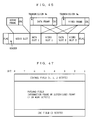
- FIG.47 shows a frame structure of PIAFS.
- the frame type identification field contains a frame type
- the error control field contains a transmission frame number and an oldest unreceived frame number
- the user data length indication field contains the data length of significant data in the user data field
- the user data field contains user data
- the error detection code field contains an error detection code for detecting error of the entire ARQ frame.
- PIAFS frame synchronization is established prior to a communication by using a synchronizing frame including a synchronization flag and the frame synchronization is kept by using data frames having the same length as the synchronizing frame, which requires no synchronization flag in the data frames.
- the PIAFS with fixed-length ARQ frames, is not susceptible to error because the frame synchronization is not lost even if an error occurs.
- each fixed-length frame is provided with a header showing whether the contents are HDLC data or not.
- the fixed-length frame contains a non-HDLC fixed-length packet (e.g., an audio data packet).
- the header indicates HDLC data
- the fixed-length frame contains part of a divided variable-length HDLC frame (e.g., a video frame).
- the multiplex frames as having a fixed length provide error robustness.
- the video data still adopt the HDLC flag synchronization and are stored over a plurality of multiplex frames. Accordingly, the video frames are still easily affected by error.
- a method for comparing a predetermined threshold and the number of cells in a buffer having a capacity twice the maximum fluctuation time to control reading of the buffer is suggested.
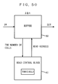
- Fig.49 shows the structure thereof.
- the buffer 50 has a capacity of 2 ⁇ t, twice the jitter ⁇ t.
- the reading control portion 60 compares the number of cells accumulated in the buffer 50 and a predetermined threshold. When the number of accumulated cells exceeds the threshold, it outputs a reading address to start reading the buffer 50.
- the jitter correcting circuit of Fig.49 is so structured as to read contents of the buffer 50 after a maximum delay time in the ATM network has passed after arrival of the first cell.
- the average delay time increases as the cells are accumulated to the threshold, increasing delay of audio.
- the multiplex layer discards data in the information field when an error is found in the multiplex header. Accordingly, it is when the sequence error is detected from the frame number of the ARQ header of the video frame received next without error that a retransmission request for the video frame in the discarded information field is sent out from the error control processing layer. For example, if a transmission error occurs in the multiplex header of the multiplex frame of the frame number (1) transmitted from the transmitting terminal, the receiving terminal discards video data in the multiplex frame after receiving the multiplex header.
- the receiving terminal can not immediately send a reject for the video data of the frame number (1). That is to say, the receiving terminal finds the absence of the multiplex frame of the frame number (1) only after it receives the multiplex frame of the frame number (2), and then it transmits a reject for the frame number (1) to the transmitting side.
- the receiving side can, even if the information part is discarded, immediately transmit a retransmission request for the frame as long as the frame number of that frame correctly arrives at the receiving side. This reduces the retransmission waiting time.
- a first object of the present invention is to provide a multiplex transmission method having error robustness and good transmission efficiency.
- a second object of the present invention is to provide a multiplex transmission method capable of correcting audio jitter without increasing delay time of audio.
- the present invention has the following features to achieve the objects above.
- a first aspect of the present invention is directed to a method for multiplexing and transmitting variable-length data employing retransmission to which error correction by retransmission control is applied and fixed-length data not employing retransmission to which error correction by retransmission control is not applied in multiplex frames, wherein the multiplex frames have a fixed length and a data link frame for storing the variable-length data employing retransmission has a frame length increased/decreased depending on the length of the fixed-length data not employing retransmission to be multiplexed so that the data link frame is transmitted at timing kept in synchronization for each multiplex frame with the transmission stream of the multiplex frames.
- the multiplex frames for storing the fixed-length data not employing retransmission and the variable-length data employing retransmission have a fixed length and a data link frame for storing the variable-length data employing retransmission has a frame length changed depending on the length of the fixed-length data not employing retransmission to be multiplexed so that the data link frames can be transmitted at timing synchronized with the transmission stream of the multiplex frames. Then the transmitting timing of the data link frames can be fixed and the boundaries between the data link frames are not lost in the event of a transmission error, providing error robustness.
- variable-length data employing retransmission transmitted in the second variable-length slot when variable-length data employing retransmission transmitted in the second variable-length slot is errored, the variable-length data employing retransmission can be retransmitted in either of the second variable-length slot and the fixed-length slot.
- a sixteenth aspect of the present invention is directed to a method of absorbing audio jitter on the side receiving multiplex frames when a low-bitrate-coded N-byte (N is a positive integer) audio frame generated at a rate of one frame per an F-byte (F is a positive integer and N ⁇ F) transmission time is stored and multiplexed in an M-byte (M is a positive integer and M ⁇ F) fixed-length multiplex frame and when at most J-byte (J is a positive integer) audio jitter is generated among the audio fields of the multiplex frames because F/M is not an integer, wherein a reference audio frame separated from the next audio frame at a minimum interval is identified from among the audio frames on the transmitted multiplex frame stream, and using the timing at which the reference audio frame is outputted as a reference, the following audio frames are outputted at the rate of one frame per the F-byte transmission time.
- different multiplex information are defined for n multiplex frames containing audio frames multiplexed therein, which facilitates identification of the reference audio frame serving as a reference in the audio jitter absorption.
- a twentieth aspect of the present invention is directed to a method of absorbing audio jitter on the side receiving multiplex frames when a low-bitrate-coded N-byte (N is a positive integer) audio frame generated at a rate of one frame per an F-byte (F is a positive integer and N ⁇ F) transmission time is stored and multiplexed in an M-byte (M is a positive integer and M ⁇ F) fixed-length multiplex frame and when at most J-byte (J is a positive integer) audio jitter is generated among the audio fields of the multiplex frames because F/M is not an integer, wherein when the time from the start of a coding operation of an audio coder for coding audio data to the start of output of the first audio frame from the audio coder is taken as T, and the time required from the start of output of the first audio frame from the audio coder to the start of output of the multiplex frame containing the first audio frame is taken as ⁇ , using as a reference the timing of the start of output of the multiplex frame containing a reference audio
- the twentieth aspect it is possible, on the side receiving the multiplex frames, to easily absorb the audio jitter caused because the frame length of the multiplex frames and the cycle of transmission of the audio frames do not match.
- different multiplex information are individually defined for n multiplex frames in which an audio frame is multiplexed, which allows a reference audio frame for audio jitter absorption to be easily identified.
- a twenty-fifth aspect of the present invention is directed to a method for multiplexing a first data frame provided with a frame number and an error detecting code and second to kth data frame(s) (k is an integer of 2 or larger) in multiplex frames from a transmitting side to a receiving side, wherein the multiplex frame is further provided with multiplex information indicating the structure of the multiplexing of the first data frame and the second to kth data frame(s), the transmitting side locates the frame number of the first data frame always in a fixed position in the multiplex frame, and when detecting presence of an error in the multiplex information in the multiplex frame received, the receiving side reads the frame number of the first data frame from the fixed position in the multiplex frame and transmits a retransmission request for the read frame number to the transmitting side.
- the frame number of the first data frame is always located in a fixed position in the multiplex frame so that the receiving side can read the frame number of the first data frame from the fixed position in the multiplex frame even if an error exists in the multiplex information in the received multiplex frame and can immediately transmit a retransmission request for the read frame number to the transmitting side.
- a thirtieth aspect of the present invention is directed to a method for multiplexing a first data frame provided with a frame number and an error detecting code and second to kth data frame(s) (k is an integer of 2 or larger) in multiplex frames from a transmitting side to a receiving side, wherein the multiplex frame is further provided with multiplex information indicating in what structure the first data frame and the second to kth data frame(s) are multiplexed, wherein the transmitting side includes as transmission modes,
- the receiving side can read the frame number of the first data frame from the fixed position in the multiplex frame even if there is an error in the multiplex information in the multiplex frame transmitted in the first transmission mode and can immediately transmit a retransmission request for the read frame number to the transmitting side.
- the receiving side can easily determine in which of the first and second transmission modes the transmitting side transmits the multiplex frames on the basis of the correspondence data sent from the transmitting side in advance.
- a thirty-second aspect of the present invention is directed to a multiplex transmission method in which an audio frame having a frame length of 30 ms and being of 120 bytes when transmitted at 32 Kbps is low-bitrate-coded, and then stored and multiplexed in a multiplex frame having a frame length of 20 ms and being of 80 bytes when transmitted at 32 Kbps, wherein a basic multiplex frame stream formed of two first multiplex frames containing the audio frame and one second multiplex frame containing none of the audio frame is repeatedly transmitted.
- different multiplex information are defined for the two first multiplex frames included in the basic multiplex frame stream so that the audio frame used as a reference in absorbing the audio jitter can easily be identified.
- the video data transmitted in the third video frame when video data transmitted in the third video frame is errored, the video data can be retransmitted in either of the second and third multiplex frames.
- the ARQ headers for the first and second video frames are stored in a fixed position in the multiplex headers. This allows the receiving side to read the ARQ headers for the first and second video frames from the fixed position in the multiplex frames even if there is an error in the multiplex information in the received multiplex frame and to perform the retransmission control at once.
- the ARQ headers for the first and second video frames are each stored in a fixed position in the multiplex headers. This allows the receiving side to read the ARQ headers for the first and second video frames from the fixed position in the multiplex frames even if there is an error in the multiplex information in a received multiplex frame and can perform the retransmission control at once.
- a thirty-ninth aspect of the present invention is directed to a multiplex transmission method in which an audio frame having a frame length of 30 ms and being of 120 bytes when transmitted at 32 Kbps is low-bitrate-coded, and then stored and multiplexed in a multiplex frame having a frame length of 15 ms and being of 60 bytes when transmitted at 32 Kbps, wherein a first multiplex frame containing the audio frame and a second multiplex frame containing none of the audio frame are alternately and repeatedly transmitted.
- the video data transmitted in the third video frame when video data transmitted in the third video frame is errored, the video data can be retransmitted in any of the second and third multiplex frames.
- the ARQ headers for the first and second video frames are stored in a fixed position in the multiplex headers. This allows the receiving side to read the ARQ headers for the first and second video frames from the fixed position in the multiplex frames even if there is an error in the multiplex information in the received multiplex frame and to perform the retransmission control at once.
- the ARQ headers for the first and second video frames are stored in a fixed position in the multiplex headers. This allows the receiving side to read the ARQ headers for the first and second video frames from the fixed position in the multiplex frames even if there is an error in the multiplex information in the received multiplex frame and to perform the retransmission control at once.
- a forty-fourth aspect of the present invention is directed to a system for multiplexing variable-length data employing retransmission to which error correction by retransmission control is applied and fixed-length data not employing retransmission to which error correction by retransmission control is not applied in multiplex frames from a transmitting device to a receiving device, wherein the transmitting device provides the multiplex frame with a fixed length and increases/decreases the frame length of a data link frame for storing the variable-length data employing retransmission depending on the length of the multiplexed fixed-length data not employing retransmission to transmit the data link frame at a timing always in synchronization with the transmission stream of the multiplex frames.
- multiplex frames for storing the fixed-length data not employing retransmission and the variable-length data employing retransmission have a fixed length and data link frames for storing the variable-length data employing retransmission have a frame length changed depending on the length of the fixed-length data not employing retransmission to be multiplexed so that the data link frames can be transmitted always in synchronization with the transmission stream of the multiplex frames. Then the transmission timing of the data link frames can be fixed and the boundaries between the data link frames are not lost in the event of a transmission error, providing error robustness.
- the frame timing of the data link frames of the variable-length data employing retransmission can have the same cycle and the same rate as the frame timing of PIAFS for the PHS data communication.
- a forty-ninth aspect of the present invention is directed to a method for performing multiplex transmission between a transmitting side and a receiving side by using multiplex frames on a composite data transmission network in which a first network performing synchronous communication and a second network performing asynchronous communication are connected to each other, wherein multiplex frames containing synchronization flags at the heads are always transmitted from the transmitting side to the receiving side while the communication is continuing, and when a communication is made within the first network, frame synchronization established prior to the data communication is kept by using the multiplex frames having a fixed frame length, without using the synchronization flags.
- a fiftieth aspect of the present invention is directed to a method for performing multiplex transmission between a transmitting side and a receiving side by using multiplex frames in a composite data transmission network in which a first network performing synchronous communication and a second network performing asynchronous communication are connected to each other, wherein when the second network is interposed between the transmitting side and the receiving side, frame synchronization is acquired between the transmitting side and the receiving side by transmitting multiplex frames containing synchronization flags at the heads, and when making a communication within the first network, multiplex frames containing no synchronization flags are transmitted and frame synchronization established prior to the data communication is kept by using the multiplex frames having a fixed frame length.
- a fifty-first aspect of the present invention is directed to a method for multiplexing data employing retransmission to which error correction by retransmission control is applied and data not employing retransmission to which error correction by retransmission control is not applied by using multiplex frames on a composite data transmission path in which a first transmission path with a relatively high bit rate and a second transmission path with a relatively low bit rate are connected to each other, wherein when the multiplex frame is transmitted from the first transmission path to the second transmission path, the data not employing retransmission in which a transmission error has occurred on the first transmission path is discarded at the connection from the first transmission path to the second transmission path.
- data not employing retransmission in which a transmission error has occurred on the first transmission path is discarded at the connection from the first transmission path to the second transmission path. This prevents unwanted data from being outputted onto the second transmission path, which prevents reduction of the bit rate on the second transmission path.
- a fifty-second aspect of the present invention is directed to a method for multiplexing data employing retransmission to which error correction by retransmission control is applied and data not employing retransmission to which error correction by retransmission control is not applied by using multiplex frames on a composite data transmission path in which a first transmission path with a relatively high bit rate and a second transmission path with a relatively low bit rate are connected to each other, wherein when the multiplex frame is transmitted from the first transmission path to the second transmission path, the data employing retransmission is provided with a block-coded error correcting code and transmitted on the first transmission path, at the connection from the first transmission path to the second transmission path, the data employing retransmission is subjected to error correction with the error correcting code and then outputted onto the second transmission path with the error correcting code removed therefrom, and retransmission control thereof is performed between a transmitting terminal and a receiving terminal.
- error correction only is applied to the data employing retransmission and retransmission control is not applied to the data employing retransmission. Then the error correcting code is removed and the data employing retransmission is outputted onto the second transmission path. This lessens the amount of data outputted onto the second transmission path, which prevents reduction of the bit rate on the second transmission path.
- a fifty-third aspect of the present invention is directed to a method for multiplexing data employing retransmission to which error correction by retransmission control is applied and data not employing retransmission to which error correction by retransmission control is not applied by using multiplex frames on a composite data transmission path in which a first transmission path with a relatively high bit rate and a second transmission path with a relatively low bit rate are connected to each other, wherein when the multiplex frame is transmitted from the first transmission path to the second transmission path, the data employing retransmission is provided with a block-coded error correcting code and transmitted on the first transmission path, at the connection from the first transmission path to the second transmission path, the error correcting code is just removed, without error correction with the error correcting code, and then the data employing retransmission is outputted onto the second transmission path, and retransmission control thereof is performed between a transmitting terminal and a receiving terminal.
- retransmission control to the data employing retransmission is not performed and the error correcting code is just removed, and the data employing retransmission is then outputted onto the second transmission path. This lessens the amount of data outputted onto the second transmission path, which prevents reduction of the bit rate on the second transmission path.
- a fifty-fourth aspect of the present invention is directed to a method for multiplexing data employing retransmission to which error correction by retransmission control is applied and data not employing retransmission to which error correction by retransmission control is not applied by using multiplex frames on a composite data transmission path in which a first transmission path with a relatively high bit rate and a second transmission path with a relatively low bit rate are connected to each other, wherein when the multiplex frame is transmitted from the first transmission path to the second transmission path, the data employing retransmission is convolutional-coded with a certain code rate Rc and transmitted on the first transmission path, at the connection from the first transmission path to the second transmission path, the convolutional coding is decoded and then the data employing retransmission is outputted onto the second transmission path, and its retransmission control is performed between a transmitting terminal and a receiving terminal.
- the convolutional-coded data employing retransmission is just decoded without retransmission control, which is outputted onto the second transmission path without re-coded. This lessens the amount of data outputted onto the second transmission path, which prevents reduction of the bit rate of the second transmission path.
- a fifty-sixth aspect of the present invention is directed to a method for multiplexing data employing retransmission to which error correction by retransmission control is applied and data not employing retransmission to which error correction by retransmission control is not applied by using multiplex frames on a composite data transmission path in which a first transmission path with a relatively high bit rate and a second transmission path with a relatively low bit rate are connected to each other, wherein when the multiplex frame is transmitted from the first transmission path to the second transmission path, the data not employing retransmission is convolutional-coded with a certain code rate Rc and transmitted on the first transmission path, and at the connection from the first transmission path to the second transmission path, the convolutional coding is decoded and then the data not employing retransmission is outputted onto the second transmission path.
- the convolutional-coded data not employing retransmission is just decoded and is outputted onto the second transmission path without re-coded. This lessens the amount of data outputted onto the second transmission path, which prevents reduction of the bit rate of the second transmission path.
- a fifty-eighth aspect of the present invention is directed to a method for multiplexing data employing retransmission to which error correction by retransmission control is applied and data not employing retransmission to which error correction by retransmission control is not applied by using multiplex frames on a composite data transmission path in which a first transmission path with a relatively high bit rate and a second transmission path with a relatively low bit rate are connected to each other, wherein when the multiplex frame is transmitted from the first transmission path to the second transmission path, the data not employing retransmission is provided with a block-coded error correcting code and transmitted on the first transmission path, and at the connection from the first transmission path to the second transmission path, the data not employing retransmission is subjected to error correction with the error correcting code and then outputted onto the second transmission path with the error correcting code removed therefrom.
- the data not employing retransmission is just subjected to error correction and the error correcting code is removed, and then the data not employing retransmission is outputted onto the second transmission path. This lessens the amount of data outputted onto the second transmission path, which prevents reduction of the bit rate of the second transmission path.
- a fifty-ninth aspect of the present invention is directed to a method for multiplexing data employing retransmission to which error correction by retransmission control is applied and data not employing retransmission to which error correction by retransmission control is not applied by using multiplex frames on a composite data transmission path in which a first transmission path with a relatively high bit rate and a second transmission path with a relatively low bit rate are connected to each other, wherein when the multiplex frame is transmitted from the first transmission path to the second transmission path, the data not employing retransmission is provided with a block-coded error correcting code and transmitted on the first transmission path, and at the connection from the first transmission path to the second transmission path, the error correcting code is just removed, without error correction with the error correcting code, and then the data not employing retransmission is outputted onto the second transmission path.
- the error correcting code is just removed and then the data not employing retransmission is outputted onto the second transmission path. This lessens the amount of data outputted onto the second transmission path, which prevents reduction of the bit rate on the second transmission path.
- a sixtieth aspect of the present invention is directed to a method for multiplexing data employing retransmission to which error correction by retransmission control is applied and data not employing retransmission to which error correction by retransmission control is not applied by using multiplex frames on a composite data transmission path in which a first transmission path with a relatively high bit rate and a second transmission path with a relatively low bit rate are connected to each other, wherein when the multiplex frame is transmitted from the first transmission path to the second transmission path, the data employing retransmission is convolutional-coded with a certain code rate Rc and transmitted on the first transmission path, and at the connection from the first transmission path to the second transmission path, the convolutional coding is decoded and then the data employing retransmission is outputted onto the second transmission path, and its retransmission control is performed between a transmitting terminal and a receiving terminal, and the data not employing retransmission is convolutional-coded with a certain code rate Rc and transmitted on the first transmission
- the convolutional-coded data employing retransmission is decoded without being subjected to retransmission control, and then the data employing retransmission is outputted onto the second transmission path without being re-coded. This lessens the amount of the data employing retransmission outputted onto the second transmission path.
- the convolutional-coded data not employing retransmission is decoded and outputted onto the second transmission path without being coded again. This lessens the amount of the data not employing retransmission outputted onto the second transmission path.
- a sixty-second aspect of the present invention is directed to a method for multiplexing and transmitting variable-length data employing retransmission to which error correction by retransmission control is applied and fixed-length data not employing retransmission to which error correction by retransmission control is not applied in multiplex frames, wherein the multiplex frames have a fixed length and a data link frame for storing the variable-length data employing retransmission has a frame length increased/decreased depending on the length of the fixed-length data not employing retransmission to be multiplexed so that the data link frame is transmitted at timing kept in synchronization with the transmission stream of the multiplex frames.
- the multiplex frames for storing the fixed-length data not employing retransmission and the variable-length data employing retransmission have a fixed length and a data link frame for storing the variable-length data employing retransmission has a frame length changed depending on the length of the fixed-length data not employing retransmission to be multiplexed so that the data link frames can be transmitted at timing synchronized with the transmission stream of the multiplex frames. Then the transmitting timing of the data link frames can be fixed and the boundaries between the data link frames are not lost in the event of a transmission error, providing error robustness.
- a sixty-third aspect of the present invention is directed to a storage medium for storing software program to be executed in order to multiplex and transmit variable-length data employing retransmission to which error correction by retransmission control is applied and fixed-length data not emplying retransmission to which error correction by retransmission control is not applied in multiplex frames, wherein said software program fix a length of said multiplex frame length and increase/decrease the length of data link frame length for storing said variable-length data employing retransmission depending on the length of said fixed-length data not emplying retransmission to be multiplexed so that the data link frame is transmitted at timing kept in synchronization, for each said multiplex frame, with the transmission stream of said multiplex frames.
- a basic multiplex frame stream including at least one first multiplex frame in which said fixed-length data not employing retransmission is multiplexed and at least one second multiplex frame in which said fixed-length data not employing retransmision is not multiplexed is repeatedly transmitted.
- a sixty-fifth aspect of the present invention is directed to a storage medium for storing software program to be excuted in order to absorb the audio jitter on the side receiving multiplex frames when a low-bitrate-coded N-byte (N is a positive integer) audio frame generated at a rate of one frame per an F-byte (F is a positive integer and N ⁇ F) transmission time is stored and multiplexed in an M-byte (M is a positive integer and M ⁇ F) fixed-length multiplex frame and when at most J-byte (J is a positive integer) audio jitter is generated among the audio fields of the multiplex frames because F/M is not an integer, wherein said software program comprises
- a sixty-sixth aspect of the present invention is derected to a storage medium for storing software program to be excuted in order to absorb the audio jitter on the side transmitting multiplex frames when a low-bitrate-coded N-byte (N is a positive integer) audio frame generated at a rate of one frame per an F-byte (F is a positive integer and N ⁇ F) transmission time is stored and multiplexed in an M-byte (M is a positive integer and M ⁇ F) fixed-length multiplex frame and when at most J-byte (J is a positive integer) audio jitter is generated among the audio fields of the multiplex frames because F/M is not an integer, wherein when the time from the start of a coding operation of an audio coder for coding audio data to the start of output of the first audio frame from the audio coder is taken as T, and the time required from the start of output of the first audio frame from said audio coder to the start of output of the multiplex frame containing said first audio frame is taken as ⁇ , using as a
- a sixty-seventh aspect of the present invention is directed to a storage medium for storing software program to be executed in order to store in multiplex frames, multiplex and tranmit a first data frame provided with a frame number and an error detecting code and second to kth data frame(s) (k is an integer of 2 or larger), wherein said multiplex frame is further provided with multiplex information indicating the structure of the multiplexing of said first data frame and said second to kth data frame(s), and wherein said software program has said transmitting side locate the frame number of said first data frame always in a fixed position in said multiplex frame and when detecting presence of an error in said multiplex information in the multiplex frame received, said receiving side read the frame number of said first data frame from the fixed position in the multiplex frame and transmit a retransmission request for the read frame number to said transmitting side.
- Fig.1 is a diagram showing the structure of a fixed-length multiplex frame used in a first embodiment of the present invention.
- Fig.2 is a diagram showing the structure of a fixed-length multiplex frame used in a second embodiment of the present invention.
- Fig.3 is a diagram showing the multiplexing in the first or second embodiment, wherein audio data coded by G.723 is multiplexed with video data in the multiplex frames having a frame length set to 120 bytes and transmitted through a transmission path at 32 Kbps of PHS which is a simplified mobile telephone.
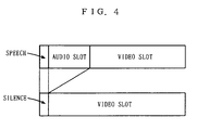
- Fig.4 is a diagram showing video slots of different sizes in a speech period and in a silent period in the multiplex frame shown in Fig.3.
- Fig.5 is a diagram showing the structure of a fixed-length multiplex frame used in a third embodiment of the present invention.
- Fig.6 is a diagram showing the structure of a fixed-length multiplex frame used in a fourth embodiment of the present invention.
- Fig.7 is a diagram showing the structure of a fixed-length multiplex frame used in a fifth embodiment of the present invention.
- Fig.8 is a diagram showing the structure of a fixed-length multiplex frame in the fourth embodiment, in which the frame length of each fixed-length multiplex frame is changed from 60 bytes to 80 bytes.
- Fig.9 is a diagram showing the structure of a fixed-length multiplex frame in the fifth embodiment, in which the frame length of each fixed-length multiplex frame is changed from 60 bytes to 80 bytes.
- Fig.10 is a layer diagram showing the structure of multiplex transmission devices in a sixth embodiment of the present invention.
- Fig.11 is a diagram showing a first example of structure of a fixed-length multiplex frame used in the multiplex transmission device of Fig.10.
- Fig.12 is a diagram showing a second example of structure of a fixed-length multiplex frame used in the multiplex transmission device of Fig.10.
- Fig.13 is a diagram showing a first structure and the data reading timing of a fixed-length multiplex frame used in seventh and eighth embodiments of the present invention.
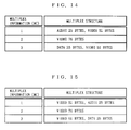
- Fig.14 is a diagram showing a first example of a multiplex code table describing the relation between the multiplex structure and the multiplex information of the fixed-length multiplex frames.
- Fig.15 is a diagram showing a second example of a multiplex code table describing the relation between the multiplex structure and the multiplex information of the fixed-length multiplex frames.
- Fig.16 is a diagram showing a second structure and the data reading timing of a fixed-length multiplex frame used in the seventh embodiment of the present invention.
- Fig.17 is a diagram showing a third structure and the data reading timing of a fixed-length multiplex frame used in the seventh embodiment of the present invention.
- Fig.18 is a diagram illustrating the reason why data is not read immediately after arrival of audio data in Fig.17.
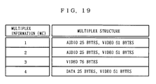
- Fig.19 is a diagram showing a third example of a multiplex code table describing the relation between the multiplex structure and the multiplex information of the fixed-length multiplex frames.
- Fig.20 is a flow chart showing processing on the receiving terminal side in a ninth embodiment of the present invention.
- Fig.21 is a diagram showing a fourth example of a multiplex code table describing the relation between the multiplex structure and the multiplex information of the fixed-length multiplex frames.
- Fig.22 is a diagram showing a second structure and the data reading timing of a fixed-length multiplex frame used in the eighth embodiment of the present invention.
- Fig.23 is a diagram showing a third structure and the data reading timing of a fixed-length multiplex frame used in the eighth embodiment of the present invention.
- Fig.24 is a timing chart showing a first example of operation on the transmitting side in a tenth embodiment of the present invention.
- Fig.25 is a timing chart showing a second example of operation on the transmitting side in the tenth embodiment of the present invention.
- Fig.26 is a timing chart showing a third example of operation on the transmitting side in the tenth embodiment of the present invention.
- Fig.27 is a diagram showing a multiplex structure of multiplex frames used in an eleventh embodiment of the present invention.
- Fig.28 is a diagram showing a multiplex structure of multiplex frames used in the eleventh embodiment of the present invention.
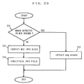
- Fig.29 is a flow chart showing processing performed by a multiplex layer on the receiving side in the eleventh embodiment of the present invention.
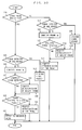
- Fig.30 is a flow chart showing processing performed by a video error control processing layer in the eleventh embodiment of the present invention.
- Fig.31 is a timing chart showing operation with retransmission control performed in the eleventh embodiment of the present invention.
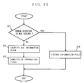
- Fig.32 is a flow chart showing processing performed by a multiplex layer on the receiving side in a twelfth embodiment of the present invention.
- Fig.33 is a flow chart showing processing performed by a video error control processing layer in the twelfth embodiment of the present invention.
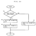
- Fig.34 is a flow chart showing processing performed by a multiplex layer on the receiving side in the twelfth embodiment of the present invention.
- Fig.35 is a diagram for describing a multiplex transmission method according to a thirteenth embodiment of the present invention.
- Fig.36 is a diagram illustrating a multiplex transmission method with each multiplex frame having a length of 60 bytes in the thirteenth embodiment of the present invention.
- Fig.37 is a diagram showing the structure of a communication system to which a fourteenth embodiment of the present invention is applied.
- Fig.38 is a diagram illustrating a multiplexing method at a terminal connected to the PHS network in the fourteenth embodiment of the present invention.
- Fig.39 is a diagram for illustrating a method of converting the rate at the network connection in the fourteenth embodiment of the present invention.
- Fig.40 is a block diagram showing the structure of the network connection in a fifteenth embodiment of the present invention.
- Fig.41 is a diagram showing a structure of a communication system to which sixteenth and seventeenth embodiments of the present invention are applied.
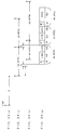
- Fig.42 is a diagram showing the structure of a multiplex frame inputted to the interconnecting device and the structure of the multiplex frame outputted from the interconnecting device in the sixteenth embodiment of the present invention.
- Fig.43 is a diagram showing the structure of a multiplex frame transmitted by a terminal connected to the PHS network in the seventeenth embodiment of the present invention.
- Fig.44 is a diagram showing a common layer structure of a conventional multiplex transmission device which adopts the multiplex transmission method determined by H.223.
- Fig.45 is a diagram showing the multiplex frame format in the multiplex layer in H.223.
- Fig.46 is a diagram showing an example of a multiplex frame format in the multiplex layer in the case where audio data, computer data and video data are multiplexed.
- Fig.47 is a diagram showing the format of the ARQ frame for error correction by retransmission control of video.
- Fig.48 is a diagram showing the frame structure defined in PIAFS.
- Fig.49 is a diagram for describing "Mixing Transfer System for HDLC Variable Length Packet and None HDLC Fixed Length Packet" disclosed in Japanese Patent Publication No.8-13057.
- Fig.50 is a block diagram showing a structure of a conventional jitter correcting circuit.
- An object of a first embodiment is to allow both of multiplex frames and video frames to easily acquire frame synchronization to provide a high tolerance for errors, when multiplexing fixed-length data not employing retransmission (audio data coded according to G.723 herein) and variable-length data employing retransmission (video data coded by H.263 herein).
- G.723 is a method for coding audio data to a rate of 5.3 Kbps, whose basic unit is formed of a 20-byte fixed-length frame.
- the fixed-length frames continue in a speech period in which audio is generated.
- the 20-byte fixed-length frames must necessarily be transmitted at a rate of one frame per 30 msec.
- an audio decoder performs processing regarding it as silent, or outputs previously transmitted background sound.
- audio data provided with a 1-byte error detecting code is transmitted.
- the receiving side adopts the so-called muting method in which the audio data is discarded when an error is detected, that is, the audio decoder performs processing regarding it as silence.
- H.263 is an image coding method for generating variable-length data, whose generated bit rate varies depending on the nature of the input image and definition, visibility, and the number of image frames of the transmitted image, and so on.
- variations in the bit rate due to retransmission control are adjusted by the coding control, too.
- the length of one fixed-length multiplex frame is 120 bytes.
- the length of an audio frame per one fixed-length multiplex frame may be set to 40 bytes or longer. In this case, however, it is necessary to store audio frames for storage in a multiplex frame, causing delay in audio.
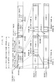
- Fig.1 is a diagram showing the structure of a fixed-length multiplex frame used in a multiplex transmission method according to a first embodiment of the present invention.
- a header is provided at the head of the fixed-length multiplex frame.
- This header at least requires the function of distinguishing between multiplexing with active speech and multiplexing with inactive speech.
- the header itself has the error detecting code or the error correcting code.
- the length of the header, including these codes, is selected to 1 byte. However, the length of the header can be decreased/increased depending on the number of patterns to be identified with the header and the error detecting or error correcting capability, which is not limited to the structure of this embodiment.
- the 120-byte fixed-length multiplex frame minus the 1-byte header, or the 119-byte fixed-length field, is divided into two, a variable-length slot 1 and a variable-length slot 2.
- the variable-length slot 1 is for transmitting an audio data link frame, whose size is equal to that of the audio data link frame, 21 bytes.
- the audio data link frame is formed of a 20-byte audio frame and a 1-byte CRC code (an error detecting code).
- the size of the variable-length slot 1 is 0 byte when there is no audio data link frame to be transmitted because speech is inactive.
- the variable-length slot 2 contains the entirety of a data link frame storing video data, the frame number, the retransmission request code, and the error detecting code.
- the data link frame is one complete frame structure as one mass of data in error control. That is to say, a multiplex transmission system to which the embodiment is applied performs retransmission control of video data in data link frame units.
- the size of the variable-length slot 2 changes depending on whether it is a speech period or a silent period. That is to say, in the case of active speech, the variable-length slot 2 has a size (98 bytes) corresponding to the fixed-length field (119 bytes) minus the variable-length slot 1 (21 bytes).
- the video data link frame is generated as a short frame having the same length of 98 bytes as the variable-length slot 2 and transmitted in the variable-length slot 2.
- the variable-length slot 2 has the same size (119 bytes) as the fixed-length field.
- the video data link frame is generated as a long frame having the same length of 119 bytes as the variable-length slot 2 and transmitted in the variable-length slot 2.
- the video data link frame may be provided with various codes depending on the method used for the retransmission control. For example, a reject code may be inserted as a retransmission request code only when an error occurs. Or, a data length code indicating the length of significant data may be provided, or stuffing (the operation of adding dummy bits in the empty part and removing them on the receiving side) may be performed, without a data length code, if an empty part takes place in the data field.
- this embodiment changes the frame length of the video data link frame depending on whether it is a speech period or a silent period.
- This enables synchronization between the transmitting timing of the fixed-length multiplex frames and the transmitting timing of the data link frames.
- variable-length slots 2 in adjacent fixed-length multiplex frames may be combined and the data link frame for video may be structured to that length.
- two video data link frames may be stored in three multiplex data link frames, or three video data link frames may be stored in four multiplex frames.
- transmission of one complete data link frame is always secured while one fixed-length multiplex frame is transmitted.
- a video data link frame is stored over a plurality of adjacent multiplex frames, it is necessary to identify said stored multiplex frames.
- each multiplex frame is completed and this provides a still higher tolerance for errors.
- the multiplex frames for carrying audio data and video data are of a fixed length and the data link frames for video have their frame lengths varied depending on whether it is in a speech period or a silent period, so as to acquire synchronization between the transmitting timing of the fixed-length multiplex frames and the transmitting timing of the data link frames.
- This enables constant transmitting timing for the data link frames, which prevents the boundaries between the data link frames from being lost in the event of a transmission error to provide robustness against errors.
- the first embodiment has explained multiplexing of the audio data and the video data
- other data such as the computer data may be transmitted as the variable-length data employing retransmission, or the audio data
- the video data and the computer data can be multiplexed to provide the same effects.
- the first embodiment has explained the case in which the audio data link frame has a length of 21 bytes, the present invention is not limited to it. That is to say, the frame length of the audio frame may be otherwise determined. Audio data link frames provided with error-correcting redundant bits having different lengths, or audio data link frames coded to another bit rate, e.g., to 6.3 Kbps, may be used as well.
- the audio data link frame in the first embodiment can take two kinds of lengths (21 bytes and 0 byte) in the speech period and the silent period, it may take three or more kinds of lengths.
- synchronization is acquired between the transmitting timing of the fixed-length multiplex frames and the transmitting timing of the data link frames by adjusting the lengths of the variable-length slots 1 and 2 according to the length of the audio data link frame and sizing the video data link frame equal to the length of the variable-length slot 2.
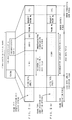
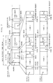
- Fig.2 is a diagram showing a structure of a fixed-length multiplex frame used in a multiplex transmission method according to a second embodiment of the present invention.
- This embodiment adopts the structure of the ARQ frame of PIAFS as a structure of the fixed-length multiplex frame. That is to say, in this embodiment, the video data as the variable-length data employing retransmission and the audio data as the fixed-length data not employing retransmission are stored in the user data field of the ARQ frame in PIAFS.
- the ARQ frame of PIAFS is a data link frame formed of the frame type identification field for storing the frame type identification code, the user data field for storing user data, the user data length indication field indicating the data length of the significant data in the user data field, the error control field for storing the frame number and the request frame number used in the retransmission control, and the error correcting code field for storing the error correcting code for detecting error in the entire ARQ frame.
- the user data field is divided into a data field for variable-length data employing retransmission and a data field for fixed-length data not employing retransmission to store the audio data in the user data field.
- These fields are previously agreed between transmitting and receiving sides.
- audio data is coded by using G.723, audio data is generated at 20 bytes/30 msec. In the G.723 system, however, no audio data is generated if it is silent during the unit time of 30 msec. When no audio data is generated, transmission is made by using the frame shown in Fig.2(b) in this embodiment.
- the transmitting side When audio data to be multiplexed exists, the transmitting side performs the transmission by using the frame of Fig.2(a). That is to say, the transmission is made with the video data stored in the data field for variable-length data employing retransmission and the audio data provided with a CRC2, an error detecting code, stored in the data field for fixed-length data not employing retransmission.
- the transmitting side conducts the transmission by using the frame of Fig.2(b). That is to say, it performs the transmission with only the video data stored in the data field for variable-length data employing retransmission.
- Stored in the frame type identification field is a code indicating whether audio data is multiplexed in the user data field and stored in the user data length indication field is the data length of the video data.
- Stored in the error control field is the frame number and the request frame number required to conduct the retransmission control defined in PIAFS.
- Stored in the error correcting code field is the CRC1, which is the error detecting code for error detection in the dotted parts in Fig.2(a) and Fig.2(b), i.e., the frame type identification field, the user data length indication field, the video data having the length shown in the user data length indication field and the error control field.
- the receiving side On receiving the fixed-length multiplex frame, the receiving side first reads the frame type identification code in the frame type identification field to determine whether audio data is multiplexed in the user data field. When audio data is multiplexed as shown in Fig.2(a), it extracts the audio data and the CRC2 from the no-retransmission-employing fixed-length data field. Then it detects error in the audio data by using the CRC2. When detecting an error, it discards the audio data, and when detecting no error, it gives the audio data to the upper layer.
- the receiving side applies the transmission control defined in PIAFS to the data left after the audio data has been extracted.
- the dotted parts correspond to the area error-detected by the CRC1. If an error is found, the data from which the audio data has been extracted is discarded.
- fixed-length data not employing retransmission control is multiplexed in the user data field of the ARQ frame defined in PIAFS. This enables multiplex transmission of video data and audio data without deteriorating the frame synchronization function providing a high tolerance for error realized in PIAFS.
- the information indicating whether audio data is multiplexed or not is included in the frame type identification code.
- the receiving side may determine that a data field for fixed-length data not employing retransmission exists only when the video data length indicated in the user data length indication field is shorter than the length of the field for variable-length data employing retransmission in Fig.2(a) to conduct the error detection of the audio data. Then if no error is found, it will give the audio data to the upper layer. This eliminates the necessity of including the information showing whether audio data is multiplexed in the frame type identification code, then the frame type identification code defined in PIAFS can be used as it is.
- the second embodiment has explained multiplexing and transmitting of the audio data and the video data
- other data such as the computer data may be transmitted as the variable-length data employing retransmission, or the audio data, the video data and the computer data can be multiplexed to provide the same effects.
- the audio data defined in PIAFS is applied to the retransmission control, but it is not limited to it.
- the retransmission control with less delay may be applied to it.
- the present invention is not limited to it. That is to say, the frame length of the audio frame may be set to another value. Audio data link frames provided with error-correcting redundant bits of different lengths, or audio frames coded to another bit rate, e.g., 6.3 Kbps, may be used as well.
- Fig.3 shows an example of multiplexing in which audio data coded by G.723 is multiplexed with video data and transmitted through the 32-Kbps transmission path of PHS, a simplified portable telephone, with the multiplex frame length set to 120 bytes.
- G.723 codes audio at a bit rate of 5.3 Kbps, wherein the audio signal is coded in 30-msec unit to form a fixed-length frame of 20 bytes. This fixed-length frame of 20 bytes is undividable and must necessarily be transmitted at a rate of one per 30 msec in a speech period.
- an audio frame of 20 bytes must be multiplexed every time 120-byte data is transmitted.
- the audio decoder on the receiving side performs processing for silence, or outputs previously transmitted background sound.
- the multiplex frame length is set to 120 bytes, the size of the video slot differs in a speech period and a silent period, as shown in Fig.4.
- a slot must include one complete ARQ frame (i.e., a data link frame). If the ARQ frame size is set equal to the slot size to improve the transmission efficiency, the size of the ARQ frame for video differs in a speech period and a silent period. Then, if a video frame transmitted in a silent period fails, it can not be retransmitted in a video slot in a speech period. The retransmission must be performed in the next silent period, or it must be performed by inserting a silent frame into a speech period in a forced manner. When the retransmission is made in the silent period coming next, a delay occurs in the retransmission data.
- ARQ frame size is set equal to the slot size to improve the transmission efficiency, the size of the ARQ frame for video differs in a speech period and a silent period. Then, if a video frame transmitted in a silent period fails, it can not be retransmitted in a video slot in a speech period. The retransmission must be performed in the next silent period,
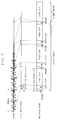
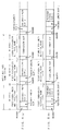
- Fig.5 is a diagram showing the structure of a fixed-length multiplex frame used in a multiplex transmission method according to the third embodiment of the present invention.
- the fixed-length multiplex frame used in this embodiment includes a header, a fixed-length field, and a fixed-length slot.
- the fixed-length field is divided into two, a variable-length slot 1 and a variable-length slot 2.
- the variable-length slot 1 contains a 20-byte audio frame plus a 1-byte CRC.
- a video data link frame is transmitted in the variable-length slot 2, whose size increases in a silent period, as has been explained in the first and second embodiments.
- the entire length of the fixed-length multiplex frame is selected to be 120 bytes.
- the length of the fixed-length slot is set equal to or longer than the length of the fixed-length field.
- the retransmission of the variable-length slot 2 is made in the fixed-length slot in this embodiment.
- the fixed-length field is set to 59 bytes and the fixed-length slot is set to 60 bytes.
- a video 1 frame with a 37-byte data link frame length is transmitted in the variable-length slot 2 and a video 2 frame with a 60-byte data link frame length is transmitted in the fixed-length slot. It is then repeated, where retransmissions of the frames are conducted by using the respective slots.
- the video 1 data link frame is set to 59 bytes and transmitted in the variable-length slot 2 and the video 2 frame with a 60-byte data link frame length is transmitted in the fixed-length slot.
- a data link frame transmitted in a silent period When a data link frame transmitted in a silent period has an error, it is transmitted in the same type of slot as long as the silent period continues. If speech is generated at the time of retransmitting a long frame transmitted in a silent period, the long frame of the video 1 frame is retransmitted in the fixed-length slot, instead of transmitting a new video 2 frame. If the speech becomes inactive at the time of retransmitting a video 1 frame transmitted in the previous speech period, it is transmitted in the long frame of the video 1 with a data length specified or stuffing.
- the length of the data link frame of video data in the fixed-length field is increased/decreased depending on the length of the audio frame to keep the transmitting timing of the fixed-length multiplex frames and the transmitting timing of the data link frames in synchronization. Then the boundaries between the data link frames will not be lost due to a transmission error, providing improved error robustness. Furthermore, a long frame of the variable-length slot 2 can be retransmitted by using a fixed-length slot without waiting for the next silent period to come, enabling retransmission without video delay.
- the third embodiment has described a multiplex transmission for transmitting audio data and video data
- other data such as computer data may be transmitted as the variable-length data employing retransmission.
- multiplex and transmit audio data, computer data and video data by transmitting the video data in the variable-length slot 2 and transmitting the computer data in the fixed-length slot, for example, through the silent periods can not be effectively utilized in this case.
- variable-length slots 2 in adjacent fixed-length multiplex frames may be combined and the data link frame for video data may be structured to that length.
- the present invention is not limited to it. That is to say, the frame length of the audio frame may take other values. Audio data link frames provided with redundant bits for error correction, or audio frames coded to another bit rate, e.g., 6.3 Kbps, may be used as well.
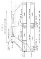
- Fig.6 is a diagram showing the structure of a fixed-length multiplex frame used in a multiplex transmission method according to a fourth embodiment of the present invention.
- this embodiment alternately and continuously transmits a 60-byte first fixed-length multiplex frame containing a header, a variable-length slot 1, and a variable-length slot 2 and a second fixed-length multiplex frame having the same length as the first fixed-length multiplex frame and containing a fixed-length slot in the part other than the header.
- the internal structure of the first fixed-length multiplex frame is the same as that of the fixed-length multiplex frame of the first embodiment. However, note that the frame length is half of that of the first embodiment (60 bytes).
- the internal structure of the second fixed-length multiplex frame includes the fixed-length slot of the third embodiment and the header.
- the fixed-length data not employing retransmission (e.g., audio data) is transmitted by using the variable-length slot 1, the variable-length data employing retransmission (e.g., video data) by using the variable-length slot 2, and the variable-length data employing retransmission (e.g., video data) by using the fixed-length slot.
- the variable-length data employing retransmission is retransmitted, when an error occurs, in the same manner as that described in the third embodiment, which is not explained again here.
- Fig.7 is a diagram showing the structure of a fixed-length multiplex frame used in a multiplex transmission method according to a fifth embodiment of the present invention.
- this embodiment transmits a 60-byte first fixed-length multiplex frame containing a header, a variable-length slot 1, and a variable-length slot 2 and a second fixed-length multiplex frame having the same length as the first fixed-length multiplex frame and containing a fixed-length slot in the part other than the header in an alternate and continuous manner.
- the first fixed-length multiplex frame has the same internal structure as the fixed-length multiplex frame of the second embodiment.
- the second fixed-length multiplex frame has the same internal structure as the PIAFS ARQ frame.
- variable-length data not employing retransmission e.g., audio data
- variable-length data employing retransmission e.g., video data
- variable-length data employing retransmission e.g., video data
- the variable-length data employing retransmission is retransmitted, when an error occurs, in the same manner as that in the third embodiment, which is not explained here again.
- the fourth and fifth embodiments have shown examples in which a 60-byte first fixed-length multiplex frame including a variable-length slot 1 for storing a 20-byte audio frame and a 60-byte second fixed-length multiplex frame including no audio frame are alternately transmitted to transmit 20-byte audio data per 120 bytes.
- the frame length of the variable-length data employing retransmission includes 40 bytes and 60 bytes.
- a still larger frame length may be suitable. Accordingly, as shown in Fig.8(a) and Fig.9(a), a 80-byte first fixed-length multiplex frame including a variable-length slot 1 for storing a 20-byte audio frame and a 80-byte second fixed-length multiplex frame including no audio frame may be transmitted in such a pattern that they appear at a ratio of 2:1.
- a 80-byte first fixed-length multiplex frame including a variable-length slot 1 capable of storing two 20-byte audio frames and a 80-byte second fixed-length multiplex frame including no audio frames may be transmitted in such a pattern that they appear at a ratio of 1:2.
- variable-length slot 2 forms a long frame when no audio frame is generated in a silent period. When an error occurs in this long frame, it is retransmitted, if the silent period is continuing, by using the variable-length slot 2 forming a long frame in the first fixed-length multiplex frame, or it is retransmitted, if speech takes place, by using the fixed-length slot of the second fixed-length multiplex frame.
- synchronization is acquired between the transmitting timing of the data link frames and the transmitting timing of the fixed-length multiplex frames by increasing/decreasing the data link frame length of the video data, or the variable-length data employing retransmission.
- This realizes video and audio multiplex transmission having error robustness and high efficiency.
- the retransmission of a long frame of the variable-length slot 2 can be made, without waiting for the next silent period to come, by using the fixed-length slot. This enables retransmission without delay of video.
- variable-length data may be transmitted as the variable-length data employing retransmission.
- the same data link frames having the same header may be used for the first fixed-length multiplex frame in which the variable-length slot 2 forms a long frame and the second fixed-length multiplex frame.
- multiplex and transmit audio data, computer data and video data by transmitting the video data in the variable-length slot 2 and transmitting the computer data in the fixed-length slot, through the silent periods can not be effectively utilized in this case.
- variable-length slots 2 in adjacent fixed-length multiplex frames may be combined and a data link frame for the video data may be structured to that length.
- the present invention is not limited to it. That is to say, the frame length of the audio frame can take other values. Audio data link frames provided with redundant bits for error correction, or audio frames coded to another bit rate, e.g., to 6.3 Kbps, may be used as well.
- the first to fifth embodiments have shown implementations in which the video data is transmitted as the variable-length data employing retransmission. Now, an implementation in which common computer data is transmitted as the variable-length data employing retransmission will be considered.
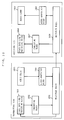
- Fig.10 is a layer diagram showing the structure of a multiplex transmission device according to a sixth embodiment of the present invention.
- the multiplex transmission device of this embodiment is so constructed as to perform the transmission control according to that suggested in the above descrived PIAFS.
- Fig.11 is a diagram showing a first example of structure of a fixed-length multiplex frame used in the multiplex transmission device of Fig.10.
- a data link frame for the variable-length data employing retransmission and a data link frame for the fixed-length data not employing retransmission are multiplexed together with the header containing the information showing the type of the multiplexing.
- the PIAFS data link processing block 1803 produces a PIAFS ARQ frame in which the significant data (the variable-length data employing retransmission) length in the user data is increased/decreased depending on presence/absence of a data link frame for the fixed-length data not employing retransmission to be multiplexed in the fixed-length multiplex frame. More specifically, the PIAFS data link processing block 1803 limits the length of the significant data in the user data under the maximum length of the user data minus the length of the data link frame for the fixed-length data not employing retransmission to be multiplexed and the header length.
- the converting block 1802 eliminates the dummy bits in the user data to convert it into a data link frame for the variable-length data employing retransmission having a reduced PIAFS user data field.
- the multiplexing block 1801 multiplexes a data link frame of fixed-length data not employing retransmission and the data link frame of the variable-length data employing retransmission and adds the header to constitute a fixed-length multiplex frame. (Refer to Fig.11(b).)
- the length of the fixed-length multiplex frame is set to the same size as the PIAFS ARQ frame length in PHS data communication (80 bytes). In this case, when they are transmitted by the method shown in the fifth embodiment (refer to Fig.9), the length of the fixed-length multiplex frames can be set to 80 bytes.
- the frame timing of the data link frames of the variable-length data employing retransmission can have the same cycle and the same rate as the frame timing of PIAFS in the PHS data communication.
- the multiplex block 1806 demultiplexes the received fixed-length multiplex frame into the data link frame of the fixed-length data not employing retransmission and the data link frame of the variable-length data employing retransmission, and gives the former to the audio adaptation block 1809 and the latter to the converting block 1807.
- the converting block 1807 inserts the fill bits "1" to the part the number is shorter than 80, between the user data field and the error detecting code to size the entirety to 80 bytes, and gives it to the PIAFS data link processing block 1808 for the PHS data communication.
- the received data can be easily converted into a PIAFS ARQ frame for PHS data communication, then a processing block for common PHS data communication can process the data.
- Fig.12 is a diagram showing a second example of structure of fixed-length multiplex frame used in the multiplex transmission device of Fig.10.
- the fixed-length multiplex frames of Fig.12 have the same structure as the ARQ frame of PIAFS, wherein the audio data, or the fixed-length data not employing retransmission, is embed and multiplexed in the user data field.
- the length of the fixed-length multiplex frame is the same as the length (80 bytes) of the PIAFS ARQ frame in the PHS data communication.
- the frame format of the fixed-length multiplex frame other than the user data field is the same as that of PIAFS in the PHS data communication.
- Stored in the user data length indication field is the length of the significant variable-length data employing retransmission.
- the multiplexing block 1806 extracts the fixed-length data not employing retransmission (audio data) from the fixed-length multiplex frame received and gives it to the audio adaptation block 1809.
- the multiplex block 1806 gives the fixed-length multiplex frame to the converting block 1807 as it is.
- the converting block 1807 entirely fills the field for the fixed-length data not employing retransmission with the fill bits "1" and gives it to the PIAFS data link processing block 1808 for PHS data communication. This allows the received data to be easily converted into a PIAFS ARQ frame for PHS data communication, which allows a processing block for performing common PHS data communication to process the data.
- the frame length corresponds to the audio frame generation cycle divided by an integer. For example, G.723 generates an audio frame with a cycle of 30 msec. If it is transmitted at 32 Kbps, the cycle is 120 bytes. Accordingly, it is desirable that the multiplex frame length is set to 120 bytes, 60 bytes, or 40 bytes.
- these multiplex frame lengths are not necessarily suitable.
- PIAFS it is possible to select the communication protocol by in-band negotiation. When the AV multiplex communication is selected, a multiplex frame length of 80 bytes enables continuous utilization of the synchronization established by PIAFS. This improves the transmission efficiency and reduces the processing procedure.
- a low-bitrate-coded 25-byte audio frame generated at the rate of one frame per 120-byte transmission time is carried on a multiplex frame with a fixed length of 80 bytes (refer to Fig.13(a))
- one multiplex frame having no multiplexed audio frame appears in every three multiplex frames. This causes jitter of 40 bytes in the time intervals between the audio frames.
- Fig.13(b). the variation in the relative time intervals between the audio frames (repeating 80-byte intervals and 160-byte intervals) with respect to the expected cycle (120 byte cycle) is defined as jitter.
- a seventh embodiment is directed to a method for absorbing the jitter on the side receiving the multiplex frames.
- Fig.13 is a diagram for use in describing the jitter absorbing method according to the seventh embodiment of the present invention.
- the multiplex information MC in Fig.13(a) includes numbers indicating the multiplex structure of the multiplex frames.
- the relation between the numbers and the multiplex structure is signaled from the transmitting side to the receiving side prior to the transmission of AV signal. It is now assumed that the relation between the multiplex structure and the multiplex information is specified by using the multiplex code table shown in Fig.14.
- Each multiplex frame has a fixed length of 80 bytes. Accordingly, two 120-byte-cycle audio frames are included in every three multiplex frames.
- an audio frame multiplexed from the next audio frame at a relatively short time interval (the 80-byte interval) and an audio frame multiplexed from the next audio frame at a relatively long time interval (the 160-byte interval) alternately repeat.
- the audio frame separated from the next audio frame at the relatively short time interval on the multiplex frame stream is outputted immediately after the reception without being stored in the buffer.
- the audio frames received before elapse of the 120-byte time are accumulated in the buffer so that the audio frames can be outputted on the 120-byte time cycle. This eliminates the delay of the 40-byte time which the conventional art has been suffered from. (Refer to Fig.13(c).)
- the seventh embodiment enables elimination of jitter without causing delay when 120-byte cycle audio is multiplexed and transmitted on 80-byte fixed-length multiplex frames.
- the jitter absorbing method of this embodiment is combined with the PIAFS devised as a transmission control method for transmitting computer data through the radio channel of PHS having a bit rate of 32 Kbps, the audio data can be multiplexed and transmitted without causing jitter and delay while adopting the multiplex frame length providing good transmission efficiency.
- Methods for identifying the audio frame separated from the next audio frame in a relatively short time on the multiplex frame stream include the following methods, for example: A first method is to receive a plurality of multiplex frames first to acquire synchronization to the pattern of the multiplex frame stream; and a second method is to settle between the transmitting side and the receiving side in advance that a perdetermined multiplex frame (i.e., the multiplex frame containing an audio frame separated from the next audio frame in a relatively short time) always comes first.
- a perdetermined multiplex frame i.e., the multiplex frame containing an audio frame separated from the next audio frame in a relatively short time
- the timing will be like that shown in Fig.13(a), (b), (c).
- the relation between the multiplex structure and the multiplex information is defined by using the multiplex code table of Fig.15
- the timing will be like that shown in Fig.16(a), (b), (c).
- the audio data and video data are multiplexed in this order in a multiplex frame with each multiplex frame provided with two multiplex headers at the head and the end, the timing will be like that shown in Fig.17(a), (b), (c).
- the seventh embodiment has shown an example in which no synchronization flag is provided at the head of the multiplex frame.
- the present invention can be applied to provide the effects described in the embodiments as long as the audio frames are transmitted in multiplex frames of different cycle, even when the multiplex frames always have a synchronization flag at the head without utilizing synchronization by frames, or when the multiplex frames are defined by another format, or when the multiplexed information include data or control information.
- the present invention is not limited to it. That is to say, the frame length of the audio frame can take other values. Audio frames provided with redundant bits for error correction, or audio frames coded to another bit rate, e.g., 6.3 Kbps, may be used as well.
- the audio frames can not be decoded until synchronization has been acquired to the pattern of the multiplex frame stream. That is to say, the first active speech can not be reproduced in the first method. Furthermore, in the first method, if a silent frame is generated first, a single audio frame can not be reproduced until active speech frames are successively generated. On the other hand, in the second method, if a transmission error occurs in the multiplex frame, it becomes impossible to know which is the first multiplex frame.
- any of the methods if a reference audio frame is missed, the next audio frame does not arrive even when a 120-byte time has passed. However, the audio decoder recognizes it just as a silent period and continues decoding. As a result, the audio sounds strange to listeners but the decoder can not recognize it.
- an eighth embodiment of the invention realizes a method for enabling identification of a reference audio frame prior to transmission/reception of the audio frames.
- the eighth embodiment uses the multiplex code table shown in Fig.19 to define the relation between the multiplex structure and the multiplex information.
- Fig.13(d) shows an example of a multiplex frame stream used in the eighth embodiment.
- the relation between the frame numbers and the multiplex structures is defined on the transmitting side and transferred to the receiving side prior to a transmission of the audio and video data. Accordingly, the receiving side easily recognizes, at the time of receiving the multiplex information (MC), that different, two kinds of multiplex information are assigned to the multiplex frames having the same kind of multiplex structure. For example, when it is predetermined to use an audio frame multiplexed in a multiplex frame with multiplex information of a smaller MC number as a reference audio frame, the reference audio frame is instantly identified on the reception of the multiplex information in the multiplex frame.
- MC multiplex information
- a transmitting terminal does not support the function described above. In this case, however, it is possible to absorb the audio jitter if the receiving terminal has the functions of both of the seventh and eighth embodiments.
- the processing on the receiving terminal side in this case is shown in the flow chart of Fig.20.
- the receiving terminal receives, prior to a transmission of the audio/video data, the multiplex multiplex code table describing the relation between the multiplex information and the multiplex structures (Step S201).
- the receiving terminal analyzes the received multiplex information (MC) to determine whether different MC numbers are provided to multiplex frames having the same multiplex structure containing multiplexed audio frames (Step S202).
- Step S203 the receiving terminal waits for reception of a multiplex frame.
- the receiving terminal analyzes the multiplex structure of the received multiplex frame from the multiplex information (MC) included in the multiplex frame (Step S204).
- the receiving terminal determines on the basis of the result of the analysis in Step S204 whether the received multiplex frame is a multiplex frame having an audio frame multiplexed (Step S205). If no audio frame is multiplexed in the received multiplex frame, the receiving terminal returns to Step S203 to wait for reception of the next multiplex frame.
- the receiving terminal determines whether that audio frame is a reference audio frame (Step S206). If the multiplexed audio frame is not a reference audio frame, the receiving terminal returns to Step S203 to wait for reception of the next multiplex frame. On the other hand, if the multiplexed audio frame is a reference audio frame, the receiving terminal starts the audio jitter absorbing processing (Step S207). In this audio jitter absorbing processing, the audio frame received this time is transferred as a reference frame to the audio decoder without delay and the following audio frames are transferred to the audio decoder every time a 120-byte time passes. Audio frames received before the 120-byte time has passed are temporarily stored in a buffer.
- Step S208 the receiving terminal waits for reception of a multiplex frame.
- the receiving terminal analyzes the multiplex structure of the received multiplex frame from the multiplex information (MC) included in that multiplex frame (Step S209).
- the receiving terminal determines on the basis of the result of the analysis in Step S209 whether the received multiplex frame is a multiplex frame containing a multiplexed audio frame (Step S210). If no audio frame is multiplexed in the received multiplex frame, the receiving terminal returns to Step S208 to wait for reception of the next multiplex frame.
- Step S211 the receiving terminal determines whether a timer 1 has been started or not.
- This timer 1 is started when a multiplex frame containing a multiplexed audio frame is received, and stopped when a multiplex frame containing a multiplexed audio frame is received again before the time-out.
- the time-out time of the timer 1 is set larger than the shorter multiplex frame interval between audio frames in the multiplex frame stream, and smaller than the longer multiplex frame interval between the audio frames.
- the timer 1 is started in Step S212 and stopped in Step S214.
- the timer 1 is started in response to the reception of the first audio frame (Step S212). Then the second audio frame is received before the timer 1 expires, in response to which the timer 1 is stopped (Step S213). Subsequently, the timer 1 is started in Step S212 again to start the counting operation again from a 0-clear state. Next, the timer 1 time-outs before the third audio frame is received. Accordingly, the receiving terminal determines that the timer 1 has expired at the time when the third audio frame is received (Step S213) and starts the audio jitter absorbing processing (Step S207).
- the eighth and ninth embodiments allow the 120-byte-cycle audio to be multiplexed and transmitted in the 80-byte multiplex frames without jitter and delay. Furthermore, it reduces the number of initial audio frames which are not reproduced, as compared with the seventh embodiment.
- the jitter absorbing methods of these embodiments are combined with the PIAFS devised as a transmission control method for transmitting computer data through the radio channel of PHS having a bit rate of 32 Kbps, audio data can be multiplexed and transmitted without jitter and delay while adopting the multiplex frame length providing high transmission efficiency.
- the seventh to ninth embodiments have explained multiplexing and transmitting of the audio data and the video data
- other data such as the computer data may be transmitted as the variable-length data employing retransmission, or the audio data, the video data and the computer data can be multiplexed and transmitted to provide the same effects.
- Step S202 in Fig.20 determines whether a plurality of audio frames are included in one multiplex frame and Step S206 regards the leading audio frame as a reference audio frame unconditionally.
- the timing will be like that shown in Fig.23(a), (b), (c).
- the present invention can similarly provide the effects in any of the multiplex structures.
- the eighth and ninth embodiments have shown examples in which no synchronization flag is provided at the head of the multiplex frame.
- the present invention can be applied to provide the effects shown in the embodiments as long as the audio frames are transmitted in multiplex frames with different cycle, even when the multiplex frames always have a synchronization flag at the head without utilizing synchronization by frames, or when the multiplex frames are defined by another format, or when the information to be multiplexed includes data or control information.
- the present invention is not limited to it. That is to say, the frame length of the audio frame can take other values. Audio frames provided with redundant bits for error correction, or audio frames coded to another bit rate, e.g., 6.3 Kbps, may be used as well.
- the transmitting side it is necessary for the transmitting side to multiplex audio codes generated at constant intervals in the audio fields of the multiplex frames having jitter with a minimum delay. That is to say, unlike the receiving side, the transmitting side must store the audio code into the audio frame field separated at a relatively short interval from the next audio frame field with a delay equal to or larger than the jitter time, on the basis of the audio frame field separated from the next audio frame at a relatively long interval.
- a large delay time causes no problem when storing, but increases the delay time of audio reproduced on the receiving side. This brings about the necessity of preventing an increase of the delay time by making the relation between occurrence of the audio frames and the phase of the multiplex frames constant.
- the transmitting terminal shall control the operation start timing of the audio coder.
- the time from the start of the audio coder to the output of the audio code is taken as T, the jitter time of the time intervals between the audio frames in the multiplex frames as J, and the time required for determining whether the audio frame is an active speech frame or a silent frame, assembling a multiplex frame corresponding to the determination, and sending out it onto the transmission channel as ⁇ .
- the audio delay time can be minimized while absorbing the time interval jitter between the audio frames.
- the tenth embodiment of the invention determines the most suitable start timing of the audio coder.
- Fig.24 is a timing chart showing the operation on the transmitting side in the multiplex transmission method according to the tenth embodiment of the present invention.
- the relation between the multiplex structure and the multiplex information is defined by using the multiplex code table shown in Fig.14.
- Fig.24(a) shows the timing for starting the audio coder.
- T is the time required from when the audio coder is started to when the audio code is outputted.
- Fig.24(b) shows the timing of output of the audio code from the audio coder.
- Fig.24(c) shows the timing at which the multiplex frame is outputted onto the transmission channel.
- the character ⁇ represents the time margin required to determine whether speech is active or inactive after the audio frame is outputted, assemble a multiplex frame corresponding to the determination, and send out it onto the transmission channel.
- ⁇ is set to a value larger than the longer one of the time margins for the speech period and the silent period.
- this embodiment sets the start timing of the audio coder so that it starts preceding the reference time for the total time ( T+J+ ⁇ ). If the time difference between the start timing of the audio coder and the time at which the first multiplex frame is sent out onto the transmission channel is set to a value larger than the total time ( T+J+ ⁇ ), it causes no problem when multiplexing, but leads to an audio delay. Accordingly, it is desirable that the time difference is set as close to the total time ( T+J+ ⁇ ) as possible.
- the tenth embodiment thus enables multiplexing and transmitting of the 120-byte cycle audio on the 80-byte multiplex frames without jitter nor delay.
- the jitter absorbing method of this embodiment is combined with PIAFS devised as a transmission control method for transmitting computer data on the radio channel of PHS having a bit rate of 32 Kbps, the audio data can be multiplexed and transmitted without jitter and delay while adopting the multiplex frame length providing high transmission efficiency.
- the timing is like that shown in Fig.26 when the video data and the audio data are multiplexed in this order.
- the timing of Fig.26 is based on the fact that it must be known whether the audio frame is speech-active or speech-inactive at the time of determining the frame structure. In any cases, the present invention provides the same effects as the tenth embodiment.
- the present invention is not limited to it. That is to say, the frame length of the audio frame can take other values. Audio frames provided with redundant bits for error correction, or audio frames coded to another bit rate, e.g., 6.3 Kbps, may be used as well.
- Described next is a multiplex transmission method which enables analysis of the ARQ header of the video frame and an immediate retransmission request even if the multiplex header of the multiplex frame has an error.
- Fig.28 is a diagram showing multiplex structures of multiplex frames used in the multiplex transmission method according to the eleventh embodiment of the invention.
- the video frame is always multiplexed in the preceding position in the information field.
- the ARQ header of the video frame can be always located in the same position, irrespective of whether an audio frame is multiplexed in the information field (Fig.28(a)) or no audio frame is multiplexed (Fig.28(b)). This allows the receiving side to know the position of the ARQ header of the video frame even if the multiplex header has an error.
- Fig.29 is a flow chart showing the processing performed by the multiplex layer on the receiving side.
- the multiplex layer on the receiving side first applies error detection to the multiplex header (Step S01). If the multiplex header has no error, the multiplex layer analyzes the multiplex information block (Step S02), demultiplexes the information field into the video frame, the audio frame, or the like, according to the multiplex information, and gives them to the corresponding error control processing layers (Step S03). On the other hand, when detecting an error in the multiplex header, the multiplex layer extracts the ARQ header of the video frame stored in the fixed position in the multiplex frame and gives it to the video error control processing layer (Step S13).
- Fig.30 is a flow chart showing the processing performed by the video error control processing layer.
- the error control layer first determines whether it has received a demultiplexed video frame from the multiplex layer (Step S14).
- the error control processing layer When having received a demultiplexed video frame from the multiplex layer (that is, when the multiplex header has no error), the error control processing layer performs error correction and error detection of the ARQ header (Step S05). If the ARQ header has no error, the error control processing layer reads the frame number (Step S06). Next, the error control processing layer determines whether a sequence error has been detected, or whether the read frame number differs from the frame number to be received next (Step S07). When a sequence error is detected, the error control processing layer transmits a retransmission request for the video frame of the absent frame number to the transmitting side (Step S08). Then the error control processing layer performs error detection of the video packet (Step S09).
- the error control processing layer If the video packet has no error, the error control processing layer outputs the video data to the video decoding layer (Step S10), and if the video data has an error, the error control processing layer transmits a retransmission request for that frame number to the transmitting side (Step S11). In the Step S05, when an error is detected in the ARQ header, the error control processing layer discards the video packet (Step S12).
- the error control processing layer performs error correction and error detection of the received ARQ header (Step S15).
- the error control processing layer reads the frame number (Step S16).
- the error control processing layer determines whether a sequence error has been detected, or whether the read frame number differs from the frame number to be received next (Step S17).
- the error control processing layer transmits a retransmission request for the video frame of the absent frame number to the transmitting side (Step S18).
- the error control processing layer transmits a retransmission request for that read frame number to the transmitting side (Step S19).
- the error control processing layer discards the video packet (Step S20).
- Fig.31 is a timing chart showing the operation when retransmission control is performed in the eleventh embodiment.
- R1 in Fig.31 indicates a reject transmitted back for the video 1.
- the terminal 2 receives it and then analyzes the ARQ header of the video frame. If the ARQ header has no error, it sends a reject. Thus the terminal 2 can immediately tramsmit back a reject for the frame number 1.
- a video frame is always multiplexed in the head part of the multiplex frame.
- the ARQ header of the video frame can be analyzed so that a reject for the video frame can immediately be transmitted back, and retransmission delay of the video frame are thus reduced.
- This embodiment provides more efficient effects when the ARQ headers are extracted only when all multiplex frames contain video data multiplexed therein.
- This embodiment is characterized in that the multiplex layer demultiplexes a video frame of certain bytes and gives it to the error control processing layer even if the multiplex header of the multiplex frame has an error.
- the receiving side determines that the ARQ headers of the video frames are not located in a fixed position in the multiplex frames.
- the multiplex layer on the receiving side performs the processing shown in Fig.32 and the video error control processing layer performs the processing shown in Fig.33.
- the multiplex layer on the receiving side first performs error detection of the multiplex header (Step S01). If the multiplex header has no error, the multiplex layer analyzes the multiplex information block (Step S02), demultiplexes the information field into the video frame, the audio frame, and so on, according to the multiplex information, and gives them to the corresponding error control processing layers (Step S03). On the other hand, when detecting an error in the multiplex header, the multiplex layer discards the data in the information field since the multiplex information for the information field is unknown (Step S04).
- the error control processing layer when having received a demultiplexed video frame from the multiplex layer (that is, when the multiplex header has no error), performs error correction and error detection of the ARQ header (Step S05). If the ARQ header has no error, the error control processing layer reads the frame number (Step S06). Next, the error control processing layer determines whether a sequence error has been detected, i.e., whether the read frame number differs from the frame number to be received next (Step S07). When a sequence error is detected, the error control processing layer transmits a retransmission request for the video frame of the absent frame number to the transmitting side (Step S08). Then the error control processing layer performs error detection of the video packet (Step S09).
- the video packet If the video packet has no error, it outputs the video data to the video decoding layer (Step S10), and if it has an error, it transmits a retransmission request for that frame number to the transmitting side (Step S11). In the Step S05, when an error is detected in the ARQ header, the error control processing layer discards the video packet (Step S12).
- the receiving side determines that the ARQ headers of the video frames are always located in a fixed position in the multiplex frames.
- the multiplex layer on the receiving side performs the processing shown in Fig.34 and the video error control processing layer performs the processing in Fig.33.
- the multiplex layer on the receiving side first performs error detection of the multiplex header (Step S01). If the multiplex header has no error, the multiplex layer analyzes the multiplex information block (Step S02), demultiplexes the information field into the video frame, the audio frame, and so on, according to the multiplex information, and gives them to the corresponding error control processing layers (Step S03).
- the multiplex layer demultiplexes the 51 bytes following the multiplex header as a video frame and gives it to the video error control processing layer, and demultiplexes the 25 bytes at the end as an audio frame and gives it to the audio error control processing layer (Step S21).
- Step S05 if the multiplex layer has erroneously demultiplexed the information field but the ARQ header has no error (Step S05), the video error control processing layer can correctly identify the frame number (Step S06). Then it is possible to detect an error in the video packet (Step S09) and a retransmission request for that frame can be transmitted (Step S11).
- the audio error control processing layer performs error detection of the audio packet to discard or make a retransmission of the audio packet. If, by chance, the video frame and the audio frame demultiplexed by the multiplex layer are correct, no error is detected in the video packet and the audio packet and the data are handled as valid data.
- a video frame of certain bytes from the head and an audio frame of certain bytes from the end are demultiplexed and given to the error control processing layers. This allows the video and audio error control processing layers to immediately transmitted back a reject for the errored frame, reducing the retransmission delay.
- This embodiment will more effectively provide the effects when it is determined on the basis of the multiplex code table for the multiplex structure whether the ARQ headers of the video frames are located in a fixed position in the multiplex frames and the ARQ headers are extracted only when they are located in the fixed position.
- This embodiment will provide more remarkable effects if the video frame and the audio frame are demultiplexed, when the ARQ header has an error, on the basis of a most frequently appearing one of the video and audio multiplex structures, or if they are demultiplexed by predicting the multiplex structure when the multiplex structures appear in a repeated certain pattern.
- multiplexing the computer data between the video data at the head and the audio data at the tail will allow the video data and the audio data to be extracted with priority, providing more significant effects.
- the present invention is not limited to it. That is to say, the frame length of the audio frame can take other values. Audio frames provided with redundant bits for error correction, or audio frames coded to another bit rate, e.g., to 6.3 Kbps, may be used as well.
- Fig.35 is a diagram for use in describing a multiplex transmission method according to a thirteenth embodiment of the invention. Specifically, Fig.35(a) shows a multiplex frame stream transmitted by the transmitting side, Fig.35(b) shows a multiplex frame stream received on the receiving side, and Fig.35(c) shows the timing of outputting audio on the receiving side.
- each multiplex frame in the multiplex frame stream has a 80-byte fixed length.
- the pattern repeats in which two multiplex frames with 20-byte audio frames multiplexed therein continuously appear and then one multiplex frame with no audio frame multiplexed therein appears.
- 20-byte audio is transmitted per 120 bytes.
- this video frame V5 can be retransmitted in a multiplex frame with no audio frame multiplexed (which necessarily appears once or more in successive three multiplex frames).
- the video data is always stored in the leading part of the multiplex frame. Even if an error is detected in the multiplex information, the receiving side demultiplexes the leading part as a video frame. Then, if the error exists only in the multiplex information, the demultiplexed video frame V4 can be correctly processed.
- Multiplex information MC having different values are stored in the header parts depending on the time to the next audio frame.
- an audio frame separated from the next audio frame in a relatively short time on the multiplex frame stream is immediately outputted without being accumulated and the following audio frames are outputted on the 120-byte time cycle. This enables multiplexing of audio of 120-byte cycle in 80-byte multiplex frames without jitter and delay.
- Fig.36 shows a method of multiplex transmission with each multiplex frame having a length of 60 bytes. Particularly, Fig.36(a) shows a multiplex frame stream transmitted from the transmitting side, Fig.36(b) shows a multiplex frame stream received on the receiving side, and Fig.36(c) shows the timing at which the receiving side outputs audio.
- each multiplex frame on the multiplex frame stream has a fixed-length of 60 bytes.
- a multiplex frame containing a 20-byte audio frame and a multiplex frame without an audio frame alternately repeat. This enables transmission of 20-byte audio per 120 bytes.
- the video frame V3 which includes a long frame due to silence has an error, this video frame V3 can be retransmitted in a multiplex frame containing no multiplexed audio frame (which necessarily appears once per successive two multiplex frames).
- the video data is always stored in the preceding part of the multiplex frame. Even if an error is detected in the multiplex information, the receiving side demultiplexes the head part as a video frame. This allows the demultiplexed video frame V5 to be correctly processed if only the multiplex information has an error.
- the data link frames for video data can always be obtained with constant timing when audio frames generated on the 120-byte cycle are multiplexed in 80-byte multiplex frames or when multiplexed in 60-byte multiplex frames. Accordingly, even when the silent periods are effectively used by increasing/decreasing the transmission band width for video data or computer data, or the variable-length data employing retransmission, the transmitting timing of the data link frames can be synchronized with the transmitting timing of the multiplex frames, resulting in a multiplex transmission with improved error robustness. Furthermore, retransmission of a long frame of the variable-length slot 2 can be performed by using the fixed-length slot, which enables retransmission control without delay of audio.
- the present invention is not limited to it. That is to say, the frame length of the audio frame may be otherwise determined. Audio frames provided with redundant bits for error correction, or audio frames coded to another bit rate, e.g., to 6.3 Kbps, may be used as well.
- the video data retransmission control is made between the terminal 2101 and the terminal 2103.
- the two terminals determine the maximum bit rate between the terminals according to the definition of H.324 by ITU-T at the beginning of a communication, for example. Since the PHS network has a bit rate of 32 Kbps and the PSTN has a bit rate of 28.8 Kbps, the maximum bit rate of this communication system is determined to be 28.8 Kbps.
- the video data is the data employing retransmission and is retransmitted when erroneously received.
- Video data errored in the PHS network is discarded at the network connection 2102 and a retransmission request is issued. Accordingly, if an error occurs in the video data in the PHS network, the less video data to be multiplexed is in the PSTN network, the more is retransmitted, and then the PSTN network actually has less data to be transmitted than 28.8 Kbps. That is to say, the effective bit rate falls under 28.8 Kbps.
- the radio transmission channel of PHS is more prone to errors and retransmission is made more frequently. Accordingly, the bit rate between the terminals is limited by the bit rate in the PHS network, leading to inferior transmission efficiency.
- the fourteenth embodiment described next is directed to a solution of the deterioration of the transmission efficiency.
- the terminal 2101 cuts out 308 bits from the bit stream of video data (refer to Fig.38(a)) coded by H.263 or the like and adds a 16-bit CRC and 4-bit termination bits to it as shown in Fig.38 (b).
- the CRC is the code for error detection and the termination bits are dummy bits for Viterbi decoding.
- RCPC coding rate compatible punctured convolutional coding
- the network connection 2102 releases the multiplexing of the multiplex frame shown in Fig.39(a) and demultiplexes the video data into the ARQ header and the RCPC packet, as shown in Fig.39(b).
- the network connection 2102 applies Viterbi decoding (error correction) to the RCPC packet to take out 41-byte data shown in Fig.39(c).
- the network connection 2102 adds, as shown in Fig.39(d), the previously demultiplexed 32-bit ARQ header to the head of the RCPC packet to generate 45-byte video data.
- the network connection 2102 multiplexes the 45-byte video data with the previously demultiplexed 21-byte audio data to generate the 72-byte multiplex frame shown in Fig.39(e) and transmits it on the PSTN network.
- the code rate is determined as follows.
- the code rate must be 8/n (8 ⁇ n ⁇ 32). Hence, considering that the condition 41/49 ⁇ 8/9 holds, this embodiment selects the code rate of 8/9.
- the fourteenth embodiment performs error correction of video data by using convolutional coding
- block coding may be used.
- the network connection 2102 can make the rate conversion just by discarding the parity bits without performing error correction.
- the error correction coding is applied to the video data with a retransmission processing.
- the error correction coding may be applied to the audio data without the retransmission processing and the network connection 2102 may convert the code rate of the error correction coding.
- synchronization flags are provided at the heads of the multiplex frames.
- the synchronization flags are not essential.
- the PHS network and the PSTN network in the fourteenth embodiment may be a customer-provided PHS network and a customer-provided analogue telephone network.
- the fourteenth embodiment takes advantage of the fact that the PHS network has a bit rate 10% higher than that of the PSTN to increase the error correcting capability of the video data. This increases the effective bit rate in the error-prone PHS network, resulting in suppressing reduction of the transmission efficiency between terminals.
- retransmission control of video data is performed between the terminal 2101 and the network connection 2102 and between the network connection 2102 and the terminal 2103.
- the PHS network has a bit rate of 32 Kbps
- the PSTN has a bit rate of 28.8 Kbps
- the network connection 2102 performs conversion of the bit rate and conversion of multiplexing.
- the terminal 2101 multiplexes and transmits data cut out from the video bit stream coded by H.263 or the like and audio data at 32 Kbps.
- the network connection 2102 includes a first multiplexing block 2401, a second multiplexing block 2402 and a video buffer 2406.
- the first multiplexing block 2401 includes a multiplex layer 2403, a video error control block 2404, and an audio discarding block 2405.
- the multiplex layer 2403 in the first multiplexing block 2401 releases the multiplexing of a multiplex frame received from the PHS network and demultiplexes the multiplex frame into video data and audio data.
- the video error control block 2404 performs error correction or error detection of the video data and performs retransmission control of error-uncorrected or error-detected video data.
- the video error control block 2404 rearranges the video data subjected to the retransmission control in the order of the sequence numbers to generate a bit stream having no error and stores it in the video buffer 2406.
- the audio discarding block 2405 performs error detection of the audio data, and discards error-detected audio data and outputs error-free audio data only to the second multiplexing block 2402.
- the second multiplexing block 2402 multiplexes the bit stream of the error-free video data stored in the video buffer 2406 and the error-free audio data at 28.8 Kbps. If an error occurs in the audio data and the audio data is discarded, the second multiplexing block 2402 assigns that band to the video data in multiplexing.
- the effective bit rate in the PHS network is larger than that in the PSTN network, data is accumulated in the video buffer 2406 to cause an overflow.
- the video retransmission control block 2404 sends a retransmission request for the data which could not be stored into the buffer to the transmitting terminal 2101. Therefore, actually, the effective bit rate in the PHS network does not exceed the effective bit rate in the PSTN network.
- the bit rate between the two terminals is equal to the effective bit rate in the PSTN network unless the effective bit rate in the PHS network falls under the effective bit rate in the PSTN network. This prevents a decrease of the transmission efficiency.
- the transmission efficiency can be further increased by assigning the field for the errored audio data to the video data.
- synchronization flags are provided at the heads of the multiplex frames.
- the synchronization flags are not essential.
- the PHS network and the PSTN network in this embodiment may be a customer-provided PHS network and a customer-provided analogue telephone network.
- a PHS network is connected to an existing analogue public switched telephone network PSTN, in which a terminal 2601 connected to the PHS network communicates with a terminal 2602 connected to the PHS network and a terminal 2604 connected to the PSTN.
- the interconnecting device 2603 has a function of PHS bearer communication, a function of communication in a PSTN analogue telephone network through a modem, a function of acquiring frame synchronization of the multiplex frames in the individual networks, and a function of rate conversion.
- Fig.42(a) shows a structure of a multiplex frame transmitted by the terminal 2601 connected to the PHS network.
- the multiplex frame has the same frame length of 80 bytes as the data frame in the PIAFS and contains "01010000111011110010100110010011" as a synchronization flag in the head part of the frame, for example. This is followed by a header including the multiplex information, and multiplexed audio data and video data, and then 8-byte dummy bits are filled.
- the terminal 2602 and the interconnecting device 2603 establish frame synchronization by using the PIAFS synchronization frame since the multiplex frames has the same frame length as the PIAFS data frame.
- the interconnecting device 2603 eliminates the fill bits to convert the multiplex frame shown in Fig.42(a) into the multiplex frame shown in Fig.42(b) to convert the bit rate.
- the terminal 2604 receives the multiplex frames while keeping frame synchronization by using the synchronization flags at the heads of the multiplex frames of Fig.42(b).
- the terminal 2602 and the interconnecting device 2603 do not require the function of searching in the synchronization flags at the heads of the multiplex frames, and the interconnecting device 2603 is not required to newly add the synchronization flags.
- the method shown in the fourteenth embodiment is also applicable as well as the method of eliminating previously inserted fill bits.
- This embodiment can be applied to the multiplex transmission methods explained in the first to fifth, tenth and eleventh embodiments to provide the effects of both of the embodiments.
- the PHS network and the PSTN network in this embodiment may be a customer-provided PHS network or a customer-provided analogue telephone network, respectively.
- the multiplex frames after the synchronization has been established by the synchronization frame may be transmitted with a synchronization flag at each head and then it will be negotiated whether to remove the synchronization flag.
- a PHS network is connected to an existing analogue public switched telephone network PSTN, in which the terminal 2601 connected to the PHS network communicates with the terminal 2602 connected to the PHS network and the terminal 2604 connected to the PSTN.
- the interconnecting device 2603 has a function of PHS bearer communication, a function of communication in a PSTN analogue telephone network through a modem, a function of acquiring frame synchronization of the multiplex frames in the individual networks, and a function of the bit rate conversion.
- Fig.43 shows a structure of a multiplex frame transmitted by the terminal 2601 connected to the PHS network.
- the multiplex frame has the same frame length of 80 bytes as the PIAFS data frame.
- the terminal 2602 and the interconnecting device 2603 establish frame synchronization by using the PIAFS synchronization frame.
- the terminal 2601 uses, as shown in Fig.43(b), a multiplex frame having a synchronization flag stored at its head, as in the sixteenth embodiment.
- the other terminal uses a multiplex frame having no synchronization flag at its head, as shown in Fig.43(c). In this case, fill bits are not inserted into the multiplex frame since the bit rate conversion is not required.
- unnecessary synchronization flags are not provided when the other party is connected to the PHS network so that more data can be multiplexed. This improves the transmission efficiency.
- This embodiment can be applied to the multiplex transmission methods explained in the first to fifth, tenth and eleventh embodiments to provide the effects of both of the embodiments.
- the PHS network and the PSTN network in this embodiment may be a customer-provided PHS network or a customer-provided analogue telephone network, respectively.
- the multiplex frame after establishment of the synchronization frame may be transmitted with a synchronization flag at its head and then it may be negotiated as to whether to remove the synchronization flag.
- the multiplex transmission system, the multiplex transmission device and the jitter absorbing system described in the above first to seventeenth embodiments may be realized by each dedicated circuit device or a computer device.
- software program for storing the procedure of processing in the above each embodiment is executed by the computer device.
- the present invention is further directed to a storage medium for storing software program, such as a flexible disk, CD-ROM, a hard disk device, a semiconductor memory and so on.
Landscapes
- Engineering & Computer Science (AREA)
- Multimedia (AREA)
- Signal Processing (AREA)
- Time-Division Multiplex Systems (AREA)
- Detection And Prevention Of Errors In Transmission (AREA)
Applications Claiming Priority (10)
| Application Number | Priority Date | Filing Date | Title |
|---|---|---|---|
| JP113446/96 | 1996-05-08 | ||
| JP11344696 | 1996-05-08 | ||
| JP134643/96 | 1996-05-29 | ||
| JP13464396 | 1996-05-29 | ||
| JP187153/96 | 1996-07-17 | ||
| JP18715396 | 1996-07-17 | ||
| JP31326696 | 1996-11-25 | ||
| JP313266/96 | 1996-11-25 | ||
| JP727597 | 1997-01-20 | ||
| JP7275/97 | 1997-01-20 |
Publications (2)
| Publication Number | Publication Date |
|---|---|
| EP0806873A2 true EP0806873A2 (de) | 1997-11-12 |
| EP0806873A3 EP0806873A3 (de) | 1998-11-18 |
Family
ID=27518802
Family Applications (1)
| Application Number | Title | Priority Date | Filing Date |
|---|---|---|---|
| EP97107526A Withdrawn EP0806873A3 (de) | 1996-05-08 | 1997-05-07 | Multiplex-Übertragungsverfahren und -system, und Audiogitterabsorptionsverfahren dafür |
Country Status (6)
| Country | Link |
|---|---|
| US (1) | US6233251B1 (de) |
| EP (1) | EP0806873A3 (de) |
| KR (1) | KR19980069768A (de) |
| CN (1) | CN1170285A (de) |
| SG (1) | SG71709A1 (de) |
| TW (1) | TW358277B (de) |
Cited By (4)
| Publication number | Priority date | Publication date | Assignee | Title |
|---|---|---|---|---|
| WO2003071777A3 (en) * | 2002-02-21 | 2004-02-26 | British Telecomm | Video processing |
| US6947447B1 (en) * | 1997-05-15 | 2005-09-20 | Canon Kabushiki Kaisha | Image communication apparatus, image communication method and recording medium which stores the sound and image |
| US6959020B1 (en) | 1998-06-30 | 2005-10-25 | Nokia Mobile Phones Ltd. | Error detection in receiving multiplex signals |
| EP1670248A1 (de) * | 2004-12-09 | 2006-06-14 | OmniVision Technologies, Inc. | Videoübertragung mit niedriger Bitrate über GSM Netzwerk |
Families Citing this family (71)
| Publication number | Priority date | Publication date | Assignee | Title |
|---|---|---|---|---|
| US6034968A (en) * | 1997-09-22 | 2000-03-07 | Samsung Electronics Co., Ltd. | Adaptive multiplexing/demultiplexing method and multiplexer/demultiplexer therefor |
| JP3437070B2 (ja) * | 1997-10-20 | 2003-08-18 | 富士通株式会社 | 加入者無線アクセスシステム |
| JP3191785B2 (ja) * | 1998-07-31 | 2001-07-23 | 三菱電機株式会社 | 通信装置および通信方法 |
| US6108346A (en) * | 1998-08-27 | 2000-08-22 | Xiox Corporation | Combined synchronous and asynchronous message transmission |
| GB9821518D0 (en) * | 1998-10-02 | 1998-11-25 | Sony Uk Ltd | Digital signal processing and signal format |
| JP3097677B2 (ja) * | 1998-10-08 | 2000-10-10 | 三菱電機株式会社 | 通信装置および通信方法 |
| US6445701B1 (en) * | 1998-10-09 | 2002-09-03 | Microsoft Corporation | Channel access scheme for use in network communications |
| JP3191783B2 (ja) | 1998-10-29 | 2001-07-23 | 三菱電機株式会社 | 通信装置および通信方法 |
| WO2000027060A1 (en) * | 1998-11-02 | 2000-05-11 | Koninklijke Philips Electronics N.V. | Communication system using a multiplex signal carrying an auxiliary signal |
| EP1006689B1 (de) | 1998-11-30 | 2008-02-06 | Matsushita Electric Industries Co., Ltd. | Paketwiederübertragungskontrolle mit Prioritätsinformationen |
| DE69832205T2 (de) * | 1998-12-10 | 2006-07-13 | Nokia Corp. | Paketübertragungsverfahren und -vorrichtung |
| CN1147104C (zh) * | 1999-05-03 | 2004-04-21 | 西门子公司 | 对具有数据包的总数据流进行处理的方法和装置 |
| KR100416996B1 (ko) * | 1999-05-10 | 2004-02-05 | 삼성전자주식회사 | 이동 통신시스템에서 라디오링크프로토콜에 따른 가변 길이의 데이터 송수신 장치 및 방법 |
| KR100532321B1 (ko) * | 1999-05-21 | 2005-11-29 | 삼성전자주식회사 | 이동 통신시스템에서 라디오링크프로토콜에 따른 가변 길이의 블록 일련번호 생성 및 바이트 일련번호 확인 장치 및 방법 |
| JP3593921B2 (ja) * | 1999-06-01 | 2004-11-24 | 日本電気株式会社 | パケット転送方法および装置 |
| US6850559B1 (en) | 1999-06-28 | 2005-02-01 | At&T Corp. | System and methods for transmitting data |
| US6853686B1 (en) * | 2000-01-14 | 2005-02-08 | Agere Systems Inc. | Frame formatting technique |
| KR100657253B1 (ko) * | 2000-03-29 | 2006-12-14 | 삼성전자주식회사 | 무선 패킷 송수신 장치 및 그 방법 |
| US20020031114A1 (en) * | 2000-07-21 | 2002-03-14 | Coaxmedia, Inc. | Priority packet transmission system for telephony, latency-sensitive data, best-effort data and video streams in a shared transmission media such as passive coax distribution |
| JP3855690B2 (ja) * | 2001-02-20 | 2006-12-13 | 三菱電機株式会社 | 多重化装置、分離装置 |
| KR100857777B1 (ko) * | 2001-03-26 | 2008-09-09 | 엘지전자 주식회사 | 하이브리드 자동 재송 요구 방식을 이용한 가변 길이의 패킷 송수신 방법 |
| US6898758B2 (en) * | 2001-06-20 | 2005-05-24 | Koninklijke Philips Electronics N.V. | Cross media error protection method and system |
| US6741603B2 (en) | 2001-07-09 | 2004-05-25 | Overture Networks, Inc. | Use of a circular buffer to assure in-order delivery of packets |
| US6757292B2 (en) | 2001-07-11 | 2004-06-29 | Overture Networks, Inc. | Automatic adjustment of buffer depth for the correction of packet delay variation |
| US6728209B2 (en) | 2001-07-25 | 2004-04-27 | Overture Networks, Inc. | Measurement of packet delay variation |
| AU2004222832B2 (en) * | 2001-10-29 | 2007-03-22 | Samsung Electronics Co., Ltd. | Apparatus and method for transmitting/receiving error detection information in a communication system |
| KR100433908B1 (ko) * | 2001-10-29 | 2004-06-04 | 삼성전자주식회사 | 통신시스템의 오류 검출 정보 송수신 장치 및 방법 |
| CA2381497A1 (en) * | 2002-01-02 | 2003-08-01 | Peter F. Crombeen | Exhaust gas muffler |
| KR100460970B1 (ko) * | 2002-01-10 | 2004-12-09 | 삼성전자주식회사 | 데이터 송수신 시스템 및 방법 |
| CA2486671C (en) | 2002-05-31 | 2011-11-15 | Onkyo Corporation | Network type content reproducing system |
| JP4142917B2 (ja) * | 2002-08-23 | 2008-09-03 | 松下電器産業株式会社 | Cdma送信装置及びofdm−cdma送信装置 |
| US7388903B2 (en) * | 2002-09-18 | 2008-06-17 | Conexant, Inc. | Adaptive transmission rate and fragmentation threshold mechanism for local area networks |
| US7352774B2 (en) * | 2002-09-30 | 2008-04-01 | Arraycomm, Llc | Multiplexing different types of data sequences |
| US7051259B1 (en) * | 2002-10-08 | 2006-05-23 | Cisco Technology, Inc. | Methods and apparatus for communicating time and latency sensitive information |
| CN100583239C (zh) * | 2003-02-28 | 2010-01-20 | 松下电器产业株式会社 | 再生装置及再生方法 |
| JP2005039726A (ja) * | 2003-07-18 | 2005-02-10 | Matsushita Electric Ind Co Ltd | 基地局装置及び送信方法 |
| US9015338B2 (en) * | 2003-07-23 | 2015-04-21 | Qualcomm Incorporated | Method and apparatus for suppressing silence in media communications |
| AU2003904170A0 (en) * | 2003-08-08 | 2003-08-21 | Clipsal Intergrated Systems Pty Ltd | Radio network communication system and protocol |
| EP1668828B1 (de) * | 2003-08-15 | 2008-10-01 | Research in Motion Limited | Vorrichtung und assoziiertes verfahren zum erhalten von dienstqualitätsniveaus während der weiterreichung in einem funkkommunikationssystem |
| JP4251955B2 (ja) * | 2003-10-15 | 2009-04-08 | パナソニック株式会社 | オーディオデータのネットワーク装置、アンプ装置 |
| US7353448B1 (en) * | 2003-10-21 | 2008-04-01 | Marvell Semiconductor Israel Ltd. | Methods, architectures, circuits and systems for transmission error determination |
| KR100581060B1 (ko) * | 2003-11-12 | 2006-05-22 | 한국전자통신연구원 | 오감 데이터 동기화 전송 장치 및 그 방법과 그를 이용한실감형 멀티미디어 데이터 제공 시스템 및 그 방법 |
| US7243284B2 (en) * | 2003-12-11 | 2007-07-10 | International Business Machines Corporation | Limiting number of retransmission attempts for data transfer via network interface controller |
| US7360142B1 (en) | 2004-03-03 | 2008-04-15 | Marvell Semiconductor Israel Ltd. | Methods, architectures, circuits, software and systems for CRC determination |
| US7434150B1 (en) | 2004-03-03 | 2008-10-07 | Marvell Israel (M.I.S.L.) Ltd. | Methods, circuits, architectures, software and systems for determining a data transmission error and/or checking or confirming such error determinations |
| KR100677378B1 (ko) * | 2004-11-02 | 2007-02-02 | 엘지전자 주식회사 | Wcdma 단말기의 영상 통화 데이터 인코딩 방법 |
| US20080198877A1 (en) * | 2005-06-13 | 2008-08-21 | Nxp B.V. | Electronic Device, Method for Frame Synchronization, and Mobile Device |
| US7965736B2 (en) * | 2005-08-24 | 2011-06-21 | Qualcomm Incorporated | Transmission of multiplex protocol data units in physical layer packets |
| US8102878B2 (en) * | 2005-09-29 | 2012-01-24 | Qualcomm Incorporated | Video packet shaping for video telephony |
| KR101135101B1 (ko) * | 2005-10-17 | 2012-04-16 | 엘지전자 주식회사 | 캔에서의 데이터 길이 코드를 이용한 데이터 필드 패딩방법 |
| US8514711B2 (en) * | 2005-10-21 | 2013-08-20 | Qualcomm Incorporated | Reverse link lower layer assisted video error control |
| US8406309B2 (en) * | 2005-10-21 | 2013-03-26 | Qualcomm Incorporated | Video rate adaptation to reverse link conditions |
| US8842555B2 (en) * | 2005-10-21 | 2014-09-23 | Qualcomm Incorporated | Methods and systems for adaptive encoding of real-time information in packet-switched wireless communication systems |
| US8548048B2 (en) * | 2005-10-27 | 2013-10-01 | Qualcomm Incorporated | Video source rate control for video telephony |
| US8537197B2 (en) * | 2007-01-10 | 2013-09-17 | Qualcomm Incorporated | Content- and link-dependent coding adaptation for multimedia telephony |
| US8599884B2 (en) * | 2007-03-15 | 2013-12-03 | Nokia Corporation | System and method for implementing optimized multiplexing and power saving in a broadcast network |
| US8031656B2 (en) | 2007-06-14 | 2011-10-04 | Telefonaktiebolaget Lm Ericsson (Publ) | Semi-persistent resource allocation method for uplink transmission in wireless packet data systems |
| WO2009065144A1 (en) | 2007-11-16 | 2009-05-22 | Divx, Inc. | Chunk header incorporating binary flags and correlated variable-length fields |
| US8797850B2 (en) * | 2008-01-10 | 2014-08-05 | Qualcomm Incorporated | System and method to adapt to network congestion |
| WO2010051545A1 (en) * | 2008-10-31 | 2010-05-06 | Divx, Inc. | System and method for playing content on certified devices |
| US8385238B2 (en) * | 2009-07-10 | 2013-02-26 | Lg Electronics Inc. | Transmitting system and method of processing digital broadcast signal in transmitting system |
| US8437331B2 (en) * | 2009-07-23 | 2013-05-07 | Lg Electronics Inc. | Method and apparatus for transmitting broadcast signal in a transmitter |
| US8438449B2 (en) * | 2009-11-02 | 2013-05-07 | Lg Electronics Inc. | Method and apparatus for transmitting broadcast signal in transmitter |
| US8953640B2 (en) * | 2009-12-11 | 2015-02-10 | Lg Electronics Inc. | Transmitting system and method of processing digital broadcast signal in transmitting system |
| US8762706B2 (en) * | 2011-04-11 | 2014-06-24 | International Business Machines Corporation | Computer systems, methods and program product for multi-level communications |
| JP2013258655A (ja) * | 2012-06-14 | 2013-12-26 | Canon Inc | 情報処理装置、動画生成装置、制御方法、プログラム、及び修復方法、 |
| JP6290127B2 (ja) | 2015-03-17 | 2018-03-07 | 株式会社東芝 | 送信システム、伝送スロット化装置、受信装置及び伝送スロット作成方法 |
| CN107025948B (zh) * | 2017-05-17 | 2023-08-15 | 西安紫光国芯半导体有限公司 | 具有标志位指示数据长度的纠错功能的存储器和纠错方法 |
| US10706859B2 (en) * | 2017-06-02 | 2020-07-07 | Apple Inc. | Transport of audio between devices using a sparse stream |
| TW202101946A (zh) * | 2019-06-14 | 2021-01-01 | 日商索尼半導體解決方案公司 | 通信裝置及通信方法以及程式 |
| CN114442951B (zh) * | 2022-01-24 | 2024-08-02 | 珠海泰芯半导体有限公司 | 传输多路数据的方法、装置、存储介质和电子设备 |
Family Cites Families (5)
| Publication number | Priority date | Publication date | Assignee | Title |
|---|---|---|---|---|
| JPS5632852A (en) * | 1979-08-27 | 1981-04-02 | Fujitsu Ltd | Composite transmission system for data and sound |
| US5511073A (en) * | 1990-06-25 | 1996-04-23 | Qualcomm Incorporated | Method and apparatus for the formatting of data for transmission |
| JPH05244186A (ja) | 1991-08-06 | 1993-09-21 | Fujitsu Ltd | Atm/stm変換回路 |
| JPH0813057A (ja) | 1994-06-24 | 1996-01-16 | Saamaru:Kk | チタンの燒結板及びその製造装置 |
| US5638371A (en) * | 1995-06-27 | 1997-06-10 | Nec Usa, Inc. | Multiservices medium access control protocol for wireless ATM system |
-
1997
- 1997-05-07 SG SG1997001409A patent/SG71709A1/en unknown
- 1997-05-07 EP EP97107526A patent/EP0806873A3/de not_active Withdrawn
- 1997-05-07 TW TW086106053A patent/TW358277B/zh active
- 1997-05-08 US US08/848,470 patent/US6233251B1/en not_active Expired - Fee Related
- 1997-05-08 KR KR1019970018461A patent/KR19980069768A/ko not_active Withdrawn
- 1997-05-08 CN CN97111529A patent/CN1170285A/zh active Pending
Cited By (5)
| Publication number | Priority date | Publication date | Assignee | Title |
|---|---|---|---|---|
| US6947447B1 (en) * | 1997-05-15 | 2005-09-20 | Canon Kabushiki Kaisha | Image communication apparatus, image communication method and recording medium which stores the sound and image |
| US6959020B1 (en) | 1998-06-30 | 2005-10-25 | Nokia Mobile Phones Ltd. | Error detection in receiving multiplex signals |
| WO2003071777A3 (en) * | 2002-02-21 | 2004-02-26 | British Telecomm | Video processing |
| EP1670248A1 (de) * | 2004-12-09 | 2006-06-14 | OmniVision Technologies, Inc. | Videoübertragung mit niedriger Bitrate über GSM Netzwerk |
| US7596149B2 (en) | 2004-12-09 | 2009-09-29 | Omnivision Technologies, Inc. | Low bit rate video transmission over GSM network |
Also Published As
| Publication number | Publication date |
|---|---|
| SG71709A1 (en) | 2000-04-18 |
| US6233251B1 (en) | 2001-05-15 |
| KR19980069768A (ko) | 1998-10-26 |
| CN1170285A (zh) | 1998-01-14 |
| TW358277B (en) | 1999-05-11 |
| EP0806873A3 (de) | 1998-11-18 |
Similar Documents
| Publication | Publication Date | Title |
|---|---|---|
| US6233251B1 (en) | Multiplex transmission method and system, and audio jitter absorbing method used therein | |
| US8516326B2 (en) | Data transmission method and data transmission apparatus | |
| US6959020B1 (en) | Error detection in receiving multiplex signals | |
| US5856988A (en) | Method and apparatus for data transmission | |
| JP2002077233A (ja) | リアルタイム情報受信装置 | |
| JPH07322248A (ja) | 動画像データの伝送方法および伝送装置 | |
| JP2671821B2 (ja) | データ伝送装置 | |
| JPH09191296A (ja) | ディジタル復号化器と符号化器のクロックの同期方法及び装置 | |
| JPH10262015A (ja) | 多重伝送方法およびシステム並びにそこで用いる音声ジッタ吸収方法 | |
| JPH10247901A (ja) | 再送制御方法 | |
| JP2002185419A (ja) | 通信システムの装置において使用するための方法および装置 | |
| US6636531B1 (en) | Communication device and method | |
| CN1538679A (zh) | 时分多通道脉冲编码调制信号在以太网中传输的方法 | |
| JP2000307637A (ja) | マルチメディア端末装置及び網間接続装置 | |
| JP3207709B2 (ja) | 多重化データ相互通信方法、多重化データ相互通信システム、ゲートウエイおよび非同期網上の端末 | |
| KR100885138B1 (ko) | 이종 통신망간 접속에 있어서의 부호화 데이터의 처리방법및 게이트웨이 장치 | |
| JP3276611B2 (ja) | 可変長フレーム送信装置及び可変長フレーム送信方法 | |
| JP2002152181A (ja) | マルチメディアデータ通信方法およびマルチメディアデータ通信装置 | |
| JP3053709B2 (ja) | 信号生成装置および方法 | |
| Sherif et al. | CCITT/ANSI voice packetization protocol | |
| JP2001308923A (ja) | 音声パケット通信装置 | |
| JPH0832621A (ja) | 画像音声符号化データ伝送装置 | |
| JP3957903B2 (ja) | 画像通信システム | |
| JP2003087321A (ja) | 音声多重化方法、音声分離方法及び通信装置 | |
| JPH1065691A (ja) | セル化方法及びセル化装置 |
Legal Events
| Date | Code | Title | Description |
|---|---|---|---|
| PUAI | Public reference made under article 153(3) epc to a published international application that has entered the european phase |
Free format text: ORIGINAL CODE: 0009012 |
|
| AK | Designated contracting states |
Kind code of ref document: A2 Designated state(s): DE FR GB |
|
| PUAL | Search report despatched |
Free format text: ORIGINAL CODE: 0009013 |
|
| AK | Designated contracting states |
Kind code of ref document: A3 Designated state(s): DE FR GB |
|
| 17P | Request for examination filed |
Effective date: 19981014 |
|
| 17Q | First examination report despatched |
Effective date: 20020910 |
|
| STAA | Information on the status of an ep patent application or granted ep patent |
Free format text: STATUS: THE APPLICATION HAS BEEN WITHDRAWN |
|
| 18W | Application withdrawn |
Withdrawal date: 20021127 |