EP0806882A2 - Sub-woofer loudspeaker enclosure - Google Patents
Sub-woofer loudspeaker enclosure Download PDFInfo
- Publication number
- EP0806882A2 EP0806882A2 EP97107143A EP97107143A EP0806882A2 EP 0806882 A2 EP0806882 A2 EP 0806882A2 EP 97107143 A EP97107143 A EP 97107143A EP 97107143 A EP97107143 A EP 97107143A EP 0806882 A2 EP0806882 A2 EP 0806882A2
- Authority
- EP
- European Patent Office
- Prior art keywords
- partition
- box housing
- cover plate
- loudspeaker
- box
- Prior art date
- Legal status (The legal status is an assumption and is not a legal conclusion. Google has not performed a legal analysis and makes no representation as to the accuracy of the status listed.)
- Granted
Links
Images
Classifications
-
- H—ELECTRICITY
- H04—ELECTRIC COMMUNICATION TECHNIQUE
- H04R—LOUDSPEAKERS, MICROPHONES, GRAMOPHONE PICK-UPS OR LIKE ACOUSTIC ELECTROMECHANICAL TRANSDUCERS; ELECTRIC HEARING AIDS; PUBLIC ADDRESS SYSTEMS
- H04R31/00—Apparatus or processes specially adapted for the manufacture of transducers or diaphragms therefor
-
- H—ELECTRICITY
- H04—ELECTRIC COMMUNICATION TECHNIQUE
- H04R—LOUDSPEAKERS, MICROPHONES, GRAMOPHONE PICK-UPS OR LIKE ACOUSTIC ELECTROMECHANICAL TRANSDUCERS; ELECTRIC HEARING AIDS; PUBLIC ADDRESS SYSTEMS
- H04R1/00—Details of transducers, loudspeakers or microphones
- H04R1/20—Arrangements for obtaining desired frequency or directional characteristics
- H04R1/22—Arrangements for obtaining desired frequency or directional characteristics for obtaining desired frequency characteristic only
- H04R1/28—Transducer mountings or enclosures modified by provision of mechanical or acoustic impedances, e.g. resonator, damping means
- H04R1/2807—Enclosures comprising vibrating or resonating arrangements
- H04R1/2838—Enclosures comprising vibrating or resonating arrangements of the bandpass type
- H04R1/2842—Enclosures comprising vibrating or resonating arrangements of the bandpass type for loudspeaker transducers
Definitions
- the invention is concerned with the formation of subwoofer loudspeakers, in particular with the simplification of the manufacture of such boxes.
- the invention is therefore based on the object of specifying a subwoofer loudspeaker box which avoids the problems in production which exist according to the technology.
- the box housing is formed in one piece and provided on its inner wall with a molded-in slide-in frame, the loudspeaker box can be formed by inserting the partition wall equipped with the loudspeaker, etc. into the slide-in frame through an assembly opening which is also present in the box housing. Since the partition is provided with a cover plate, if the cover plate is larger than the mounting opening, the mounting opening is closed when the partition in the slide-in frame reaches the end position.
- the cover plate only partially seals the assembly opening, i.e. the opening that then remains can be used as a port. This eliminates the need for separate ports in the box housing.
- this cover wall can be used for heat dissipation.
- the latter is particularly advantageous if the partition is additionally equipped with an amplifier unit.
- cover plate is provided with a contact strip for contacting the loudspeaker (s) or the amplifier unit, no further installation opening in the box housing is necessary, as a result of which the sealing effort is reduced.
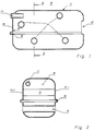
- Figure 1 shows in an essentially closed, somewhat cuboid box housing (10), the outer skin (11) of this housing (10) being broken only by an assembly opening (12) and a channel-shaped port (13). Furthermore, the interior of the box housing (10) is traversed by 4 tubular passages (14), which contribute to the mechanical stability of the box housing (10).
- an insertion frame (16) is formed on the inner wall (15) of the housing, which, as the left side of the illustration in FIG. 1 shows, has an approximately U-shaped profile.
- the right-hand side of the illustration in FIG. 1 shows that the slide-in frame (16) ends where the outer skin (11) of the housing (10) has the mounting opening (12). The latter is essential to complete the loudspeaker, as will be shown later.
- FIG. 2 which shows a section AA according to FIG. 1, can also be seen that the insertion frame (16) runs along the two side surfaces 17.1 and 17.2 and on the end surface (18) of the inner wall (16).
- box housing (10) shown in FIGS. 1 and 2 can be produced very easily from plastic by using the rotary sintering or the blowing technique.
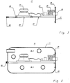
- FIG. 1 An acoustic module (19) is shown in FIG.
- This acoustic module (19) is essentially formed by a partition (20), a cover plate (21) connected to the partition (20), a loudspeaker (23) and an amplifier unit (24).
- An opening (22) over which the loudspeaker (23) is mounted is formed in the partition (20).
- the heat sinks (25) of the amplifier unit (24) are connected to the cover plate (21) and (20), which is formed from metal in the present exemplary embodiment for better heat conduction.
- the cover plate (21) can also be made of plastic and, if necessary, a one-storey unit with the partition (20 ) form.
- cover plate (21) is provided with a terminal strip (26) for contacting the amplifier unit (24).
- FIG. 4 If a fully equipped acoustic module (19) according to FIG. 3 with the peripheral edge (27) of the partition wall (20) is inserted through the assembly opening (12) FIG. 1 into the slide-in frame (16), an installation situation is achieved, which is shown in FIG. 4 is. If the acoustic module (19) has reached its end position in the box housing (10), the cover plate (21) closes the assembly opening (12). In addition, in this end position, the inside of the box housing (10) is divided into a closed volume (28.1) and an open volume (28.2) because the peripheral edge (27) of the partition (20) is mounted in the slide-in frame (16).
- peripheral edge (27) of the partition (20) is provided with a seal (29) in order to ensure the mutual sealing of the two volumes (28.1) and (28.2).
- a seal (29) is also provided between the cover plate (21) and the outer skin (11) of the box housing (10).
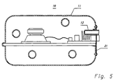
- Figure 5 shows a slightly modified version compared to Figure 4.
- the port (13) is not guided through the outer skin (11) of the box housing itself, but rather is formed in the cover plate (21).
- the port (13) is tubular.
- the port opening required in any case can also be realized by means of a hole in the cover plate (21) or by the cover plate (21) not completely covering the mounting opening (12) in the box housing (10) covered.
Landscapes
- Engineering & Computer Science (AREA)
- Manufacturing & Machinery (AREA)
- Physics & Mathematics (AREA)
- Acoustics & Sound (AREA)
- Signal Processing (AREA)
- Details Of Audible-Bandwidth Transducers (AREA)
- Vehicle Step Arrangements And Article Storage (AREA)
- Obtaining Desirable Characteristics In Audible-Bandwidth Transducers (AREA)
Abstract
Erfindungsgemäß wird ein Subwoofer - Lautsprechergehäuse angegeben, welches im wesentlichen einteilig ausgebildet ist.
Dieses einteilige Gehäuse wird durch eine Montageöffnung (12) einschiebbare Trennwand (20) komplettiert. Um die notwendige Abdichtung zwischen den durch die Trennwand (20) separierten Volumina (28.1, 28.2) herzustellen, ist an der Innenwandung (15) des Boxengehäuses (20) ein Einschubrahmen (16) angeformt. Zusätzlich ist zwischen dem Umfangsrand (27) der Trennwand (20) eine Dichtung (29) vorgesehen.
Außerdem ist die Trennwand (20) mit einer Abschlußplatte (21) versehen, welche, sobald die Trennwand (20) Ihre Endlage im Boxengehäuse (10) eingenommen hat, die Montageöffnung (12) verschließt.
This one-piece housing is completed by a partition (20) which can be inserted into an assembly opening (12). In order to produce the necessary seal between the volumes (28.1, 28.2) separated by the partition (20), an insertion frame (16) is molded onto the inner wall (15) of the box housing (20). In addition, a seal (29) is provided between the peripheral edge (27) of the partition (20).
In addition, the partition (20) is provided with an end plate (21) which, as soon as the partition (20) has assumed its end position in the box housing (10), closes the assembly opening (12).
Description
Die Erfindung befaßt sich mit der Ausbildung von Subwoofer-Lautsprecherboxen, insbesondere mit der Vereinfachung der Herstellbarkeit derartiger Boxen.The invention is concerned with the formation of subwoofer loudspeakers, in particular with the simplification of the manufacture of such boxes.
Gemäß den von der Technik ist es bekannt ein Boxengehäuse mittels einer Trennwand in zwei Volumina zu unterteilen und den Lautsprecher in die Trennwand einzusetzen. Eine solche Anordnung ist beispielsweise aus EP 0523410 bekannt. Dieser Schrift ist auch entnehmbar, daß eines der durch die Trennwand im Innern der Box gebildeten Volumina mit einem sogenannten Port versehen ist, der im Boxengehäuse angeordnet ist und der einen Luftaustausch zwischen dem Inneren des Boxengehäuses und der Box umgebenden Außenluft erlaubt. Eine Anordnung mit zwei Ports ist beispielsweise in DE 3410134 gezeigt. Obwohl die bisher beschriebenen Schritten nur die Verwendung eines Lautsprechers in der Trennwand zeigen, ist aus US 4016953 eine push-pull-Anordnung von Lautsprechern und aus EP 0379988 eine push-pull-Anordnung in Verbindung mit einer Doppelkammerbox bekannt.According to those known from the art, it is known to divide a box housing into two volumes by means of a partition and to insert the loudspeaker into the partition. Such an arrangement is known for example from EP 0523410. This document can also be seen that one of the volumes formed by the partition inside the box is provided with a so-called port, which is arranged in the box housing and which allows an air exchange between the inside of the box housing and the outside air surrounding the box. An arrangement with two ports is shown for example in DE 3410134. Although the steps described so far only show the use of a loudspeaker in the partition, a push-pull arrangement of loudspeakers is known from US 4016953 and a push-pull arrangement in connection with a double chamber box is known from EP 0379988.
Diese bisher erörterten Schriften befassen sich aber hauptsächlich mit der Wirkung derartiger Boxen und enthalten daher nur wenige bzw. gar keine Angaben zu deren Ausbildung. Mit Rücksicht auf den Umstand, daß jedoch die Trennwand zumindest einen Lautsprecher trägt, kann gesagt werden, daß derartige Boxen ein zumindest aus zwei Halbschalen gebildetes Boxengehäuse aufweisen müssen. Bezogen auf die EP 0523410 gezeigte Anordnung bedeutet dies, daß das geschlossene Volumen von einem bis auf die Einbauöffnung für den Lautsprecher geschlossenen Kasten gebildet wird und daß die Trennwand, nachdem der Lautsprecher, ect.montiert ist, mittels eines das offene Volumen bildenden wannenförmigen Haube abgedeckt wird, wobei die Ränder der Haube mit dem Kasten verschraubt oder verklebt werden. Ein ebenfalls zweiteiliges Boxengehäuse ist DE 4344618 gezeigt.However, these writings discussed so far mainly deal with the effect of such boxes and therefore contain little or no information about their training. In view of the fact that the partition carries at least one loudspeaker, it can be said that such boxes must have a box housing formed from at least two half-shells. In relation to the arrangement shown in EP 0523410, this means that the closed volume is formed by a box which is closed except for the installation opening for the loudspeaker, and that the partition, after the loudspeaker has been installed, is covered by a trough-shaped hood which forms the open volume the edges of the hood are screwed or glued to the box. A likewise two-part box housing is shown in DE 4344618.
Wenngleich diese Anordnung drei Kammern bzw. Volumina aufweist, läßt sich aus dieser Schrift die Herstellung derartiger Lautsprecherboxen mit einer in der Trennwand angeordneten Lautsprecheranordnung gut ableiten. Außerdem läßt sich dieser Schrift entnehmen, daß kompliziert geformte Boxenhalbschalen bereitgestellt werden müssen, um ein derartiges Boxengehäuse auszubilden.Although this arrangement has three chambers or volumes, the manufacture of such loudspeaker boxes with a loudspeaker arrangement arranged in the partition can be easily derived from this document. In addition, it can be seen from this document that complicatedly shaped box half-shells have to be provided in order to form such a box housing.
In diesem Zusammenhang wird außerdem als nachteilig erachtet, daß die jeweiligen Boxenhalbschalen zur Gewährleistung des späteren Einbaues von Lautsprechern mittels separater Werkzeuge hergestellt werden müssen, was die Herstellung zusätzlich verteuert.In this context, it is also considered disadvantageous that the respective box half-shells have to be manufactured using separate tools to ensure the later installation of loudspeakers, which additionally increases the cost of manufacture.
Daher liegt der Erfindung die Aufgabe zugrunde, eine Subwoofer-Lautsprecherbox anzugeben, welche die gemäß den von der Technik bestehenden Probleme bei der Herstellung vermeidet.The invention is therefore based on the object of specifying a subwoofer loudspeaker box which avoids the problems in production which exist according to the technology.
Diese Aufgabe wird durch die in Anspruch 1 angegebenen Merkmale gelöst. Vorteilhafte Aus- und Weiterbildungen der Erfindung sind den Ansprüchen 2 - 5 entnehmbar.This object is achieved by the features specified in claim 1. Advantageous further developments of the invention can be found in claims 2-5.
Es ist das Boxengehäuse einteilig ausgebildet und an seiner Innenwand mit einem angeformeten Einschubrahmen versehen, läßt sich die Lautsprecherbox dadurch ausbilden, daß die mit dem Lautsprecher, etc. bestückte Trennwand in den Einschubrahmen durch eine im Boxengehäuse außerdem vorhandene Montageöffnung eingeschoben wird. Da die Trennwand mit einer Abdeckplatte versehen ist, wird, wenn die Abdeckplatte größer ist als die Montageöffnung, die Montageöffung mit dem Erreichen der Endlage der Trennwand im Einschubrahmen verschlossen.The box housing is formed in one piece and provided on its inner wall with a molded-in slide-in frame, the loudspeaker box can be formed by inserting the partition wall equipped with the loudspeaker, etc. into the slide-in frame through an assembly opening which is also present in the box housing. Since the partition is provided with a cover plate, if the cover plate is larger than the mounting opening, the mounting opening is closed when the partition in the slide-in frame reaches the end position.
Dichtet die Abdeckplatte die Montageöffnung nur teilweise d.h. nicht vollständig ab, kann die dann verbleibende Öffnung als Port genutzt werden. Hierdurch werden separate Ports im Boxengehäuse überflüssig.The cover plate only partially seals the assembly opening, i.e. the opening that then remains can be used as a port. This eliminates the need for separate ports in the box housing.
Ist zumindest die Abdeckwand aus Metall gebildet, kann diese Abdeckwand zur Wärmeabfuhr genutzt werden. Letzteres ist insbesondere dann vorteilhaft, wenn die Trennwand zusätzlich mit einer Verstärkereinheit bestückt ist.If at least the cover wall is made of metal, this cover wall can be used for heat dissipation. The latter is particularly advantageous if the partition is additionally equipped with an amplifier unit.
Ist die Abdeckplatte mit einer Kontaktleiste zur Kontaktierung des oder der Lautsprecher bzw. der Verstärkereinheit versehen, sind keine weitere Montageöffnung im Boxengehäuse mehr notwendig, wodurch der Abdichtaufwand reduziert wird.If the cover plate is provided with a contact strip for contacting the loudspeaker (s) or the amplifier unit, no further installation opening in the box housing is necessary, as a result of which the sealing effort is reduced.
Es zeigen:
- Figur 1
- ein Boxengehäuse im Schnitt;
- Figur 2
- einen Schnitt gemäß AA gemäß Figur 1;
- Figur 3
- ein Akustikmodul in Seitenansicht
- Figur 4
- eine Kombination aus Figur 1 und Figur 3; und
- Figur 5
- eine weitere Kombination gemäß Figur 4.
- Figure 1
- a box housing in section;
- Figure 2
- a section along AA according to Figure 1;
- Figure 3
- an acoustic module in side view
- Figure 4
- a combination of Figure 1 and Figure 3; and
- Figure 5
- a further combination according to FIG. 4.
Figur 1 zeigt in ein im wesentlich geschlossenes etwas quaderförmig ausgebildetes Boxengehäuse (10), wobei die Außenhaut (11) dieses Gehäuses (10) lediglich von einer Montageöffnung (12) und einem kanalförmig ausgebildeten Port (13) durchbrochen ist. Ferner ist das Innere des Boxengehäuses (10) von 4 röhrenförmigen Durchzügen (14) durchzogen, welche zur mechanischen Stabilität des Boxengehäuses (10) beitragen.Figure 1 shows in an essentially closed, somewhat cuboid box housing (10), the outer skin (11) of this housing (10) being broken only by an assembly opening (12) and a channel-shaped port (13). Furthermore, the interior of the box housing (10) is traversed by 4 tubular passages (14), which contribute to the mechanical stability of the box housing (10).
Ferner ist im in Figur 1 dargestellten Boxengehäuse (10) ist an der Innenwand (15) des Gehäuses ein Einschubrahmen (16) ausgebildet, der, wie die linke Seite der Darstellung in Figur 1 zeigt, ein etwa u-förmig ausgebildetes Profil aufweist. Der rechter Seits in der Darstellung Figur 1 ist entnehmbar, daß der Einschubrahmen (16) dort endet, wo Außenhaut (11) des Gehäuses (10) die Montageöffnung (12) aufweist. Letzteres ist wesentlich um - wie noch später gezeigt werden wird - die Lautsprecherbox zu komplettieren.Furthermore, in the box housing (10) shown in FIG. 1, an insertion frame (16) is formed on the inner wall (15) of the housing, which, as the left side of the illustration in FIG. 1 shows, has an approximately U-shaped profile. The right-hand side of the illustration in FIG. 1 shows that the slide-in frame (16) ends where the outer skin (11) of the housing (10) has the mounting opening (12). The latter is essential to complete the loudspeaker, as will be shown later.
Die bisher im Zusammenhang mit Figur 1 gezeigten Verhältnisse werden in Figur 2 weiter veranschaulicht. Auch ist die Darstellung gemäß Figur 2, welchen einen Schnitt AA gemäß Figur 1 zeigt, entnehmbar, daß der Einschubrahmen (16) an den beiden Seitenflächen 17.1 und 17.2 sowie an der Stirnfläche (18) der Innenwandung (16) entlangläuft.The relationships previously shown in connection with FIG. 1 are further illustrated in FIG. 2. The illustration according to FIG. 2, which shows a section AA according to FIG. 1, can also be seen that the insertion frame (16) runs along the two side surfaces 17.1 and 17.2 and on the end surface (18) of the inner wall (16).
Nur der Vollständigkeit halber sei darauf hingewiesen, daß das in Figur 1 und 2 gezeigte Boxengehäuse (10) sehr einfach aus Kunststoff durch Anwendung des Rotationssinterns oder Anwendung der Blastechnik hergestellt werden kann.For the sake of completeness, it should be pointed out that the box housing (10) shown in FIGS. 1 and 2 can be produced very easily from plastic by using the rotary sintering or the blowing technique.
In Figur 3 ist ein Akustikmodul (19) gezeigt. Dieses Akustikmodul (19) wird im wesentlichen von einer Trennwand (20), eine mit der Trennwand (20) verbundenen Abdeckplatte (21), einem Lautsprecher (23) und einer Verstärkereinheit (24) gebildet. In der Trennwand (20) ist eine Öffnung (22) ausgebildet, über welcher der Lautsprecher (23) montiert ist. Die Kühlkörper (25) der Verstärkereinheit (24) sind mit der Abdeckplatte (21) und (20) verbunden, welche im vorliegenden Ausführungsbeispiel zu besseren Wärmeleitung aus Metall gebildet ist.An acoustic module (19) is shown in FIG. This acoustic module (19) is essentially formed by a partition (20), a cover plate (21) connected to the partition (20), a loudspeaker (23) and an amplifier unit (24). An opening (22) over which the loudspeaker (23) is mounted is formed in the partition (20). The heat sinks (25) of the amplifier unit (24) are connected to the cover plate (21) and (20), which is formed from metal in the present exemplary embodiment for better heat conduction.
Sofern die Wärmeableitung nur eine untergeordnete Rolle spielt oder in einem anderen - nicht dargestellten - Ausführungsbeispiel auf den Einsatz einer Verstärkereinheit (24) verzichtet wird, kann die Abdeckplatte (21) auch aus Kunststoff gebildet sein und ggf. eine einstöckige Einheit mit der Trennwand (20) bilden.If heat dissipation only plays a subordinate role or, in another embodiment (not shown), the use of an amplifier unit (24) is omitted, the cover plate (21) can also be made of plastic and, if necessary, a one-storey unit with the partition (20 ) form.
Ferner ist die Abdeckplatte (21) mit Anschlußleiste (26) zur Kontaktierung der Verstärkereinheit (24) versehen.Furthermore, the cover plate (21) is provided with a terminal strip (26) for contacting the amplifier unit (24).
Wird nun ein vollständig bestücktes Akustikmodul (19) gemäß Figur 3 mit dem Umfangsrand (27) der Trennwand (20) durch die Montageöffnung (12) Figur 1 in den Einschubrahmen (16) eingeschoben, wird eine Einbausituation erreicht, welche in der Figur 4 gezeigt ist. Hat das Akustikmodul (19) seine Endlage im Boxengehäuse (10) eingenommen, verschließt die Abdeckplatte (21) die Montageöffnung (12). Außerdem wird in dieser Endlage das Innere des Boxengehäuses (10), weil der Umfangsrand (27) der Trennwand (20) im Einschubrahmen (16) gelagert ist, in ein geschlossenes Volumen (28.1) und ein offenes Volumen (28.2) unterteilt. Der Vollständigkeit sei darauf hingewiesen, daß der Umfangsrand (27) der Trennwand (20) mit einer Dichtung (29) versehen ist, um die gegenseitige Abdichtung der beiden Volumina (28.1) und (28.2) zu gewährleisten. Auch ist zwischen der Abdeckplatte (21) und der Außenhaut (11) des Boxengehäuses (10) eine Dichtung (29) vorgesehen.If a fully equipped acoustic module (19) according to FIG. 3 with the peripheral edge (27) of the partition wall (20) is inserted through the assembly opening (12) FIG. 1 into the slide-in frame (16), an installation situation is achieved, which is shown in FIG. 4 is. If the acoustic module (19) has reached its end position in the box housing (10), the cover plate (21) closes the assembly opening (12). In addition, in this end position, the inside of the box housing (10) is divided into a closed volume (28.1) and an open volume (28.2) because the peripheral edge (27) of the partition (20) is mounted in the slide-in frame (16). For completeness, it should be noted that the peripheral edge (27) of the partition (20) is provided with a seal (29) in order to ensure the mutual sealing of the two volumes (28.1) and (28.2). A seal (29) is also provided between the cover plate (21) and the outer skin (11) of the box housing (10).
Figur 5 zeigt eine gegenüber Figur 4 leicht modifizierte Ausführung. Gemäß Figur 5 ist der Port (13) nicht durch die Außenhaut (11) des Boxengehäuses selbst geführt, sondern in der Abdeckplatte (21) ausgebildet. Auch hier ist der Port (13) rohrförmig gestaltet.Figure 5 shows a slightly modified version compared to Figure 4. According to FIG. 5, the port (13) is not guided through the outer skin (11) of the box housing itself, but rather is formed in the cover plate (21). Here too, the port (13) is tubular.
Sofern kein rohrförmiger Port (13) notwendig ist, kann die in jedem Falle erforderliche Portöffnung auch mittels einer Bohrung in der Abdeckplatte (21) oder dadurch realisiert sein, daß die Abdeckplatte (21) die Montageöffnung (12) im Boxengehäuse (10) nicht vollständig überdeckt.If no tubular port (13) is necessary, the port opening required in any case can also be realized by means of a hole in the cover plate (21) or by the cover plate (21) not completely covering the mounting opening (12) in the box housing (10) covered.
Claims (5)
dadurch gekennzeichnet,
characterized,
dadurch gekennzeichnet,
characterized,
dadurch gekennzeichnet,
characterized,
dadurch gekennzeichnet,
characterized,
dadurch gekennzeichnet,
characterized,
Applications Claiming Priority (2)
| Application Number | Priority Date | Filing Date | Title |
|---|---|---|---|
| DE29608421U DE29608421U1 (en) | 1996-05-09 | 1996-05-09 | Subwoofer speaker box |
| DE29608421U | 1996-05-09 |
Publications (3)
| Publication Number | Publication Date |
|---|---|
| EP0806882A2 true EP0806882A2 (en) | 1997-11-12 |
| EP0806882A3 EP0806882A3 (en) | 2006-05-10 |
| EP0806882B1 EP0806882B1 (en) | 2006-11-15 |
Family
ID=8023762
Family Applications (1)
| Application Number | Title | Priority Date | Filing Date |
|---|---|---|---|
| EP97107143A Expired - Lifetime EP0806882B1 (en) | 1996-05-09 | 1997-04-30 | Sub-woofer loudspeaker enclosure |
Country Status (4)
| Country | Link |
|---|---|
| US (1) | US5771302A (en) |
| EP (1) | EP0806882B1 (en) |
| AT (1) | ATE345659T1 (en) |
| DE (2) | DE29608421U1 (en) |
Cited By (1)
| Publication number | Priority date | Publication date | Assignee | Title |
|---|---|---|---|---|
| EP0991295A3 (en) * | 1998-09-28 | 2006-07-19 | Murata Manufacturing Co., Ltd. | Speaker and speaker device |
Families Citing this family (8)
| Publication number | Priority date | Publication date | Assignee | Title |
|---|---|---|---|---|
| GB2305809B (en) | 1995-09-28 | 1997-11-05 | Harman Int Ind | Power amplifier and loudspeaker frame integration |
| US6130954A (en) * | 1996-01-02 | 2000-10-10 | Carver; Robert W. | High back-emf, high pressure subwoofer having small volume cabinet, low frequency cutoff and pressure resistant surround |
| US5937074A (en) * | 1996-08-12 | 1999-08-10 | Carver; Robert W. | High back emf, high pressure subwoofer having small volume cabinet, low frequency cutoff and pressure resistant surround |
| JP3778793B2 (en) * | 2000-01-28 | 2006-05-24 | 富士通テン株式会社 | Speaker system |
| US6373957B1 (en) | 2001-05-14 | 2002-04-16 | Harman International Industries, Incorporated | Loudspeaker structure |
| KR100526599B1 (en) * | 2003-04-01 | 2005-11-08 | 삼성전자주식회사 | Speaker |
| US6944024B1 (en) | 2004-02-19 | 2005-09-13 | Audioplex Technology Incorporated | Heat sink bracket for powered loudspeaker |
| US10311495B2 (en) * | 2015-06-15 | 2019-06-04 | Timothy Val Kolton | Customizable product housing |
Family Cites Families (9)
| Publication number | Priority date | Publication date | Assignee | Title |
|---|---|---|---|---|
| US2689016A (en) * | 1953-04-14 | 1954-09-14 | Henry C Lang | Sound reproducing system |
| US4016953A (en) * | 1975-05-23 | 1977-04-12 | Butler Robert J | Push-pull transducer system |
| DE8314251U1 (en) * | 1983-05-13 | 1985-05-09 | Standard Elektrik Lorenz Ag, 7000 Stuttgart | Loudspeaker box with integrated acoustic bandpass filter |
| US4549631A (en) * | 1983-10-24 | 1985-10-29 | Bose Corporation | Multiple porting loudspeaker systems |
| DE3902343A1 (en) * | 1989-01-27 | 1990-08-02 | R & H Studiosound Beck Kg | SPEAKER BOX |
| US4939783A (en) * | 1989-01-30 | 1990-07-03 | Dunning William S | Suspended speaker system |
| DE4121408A1 (en) * | 1991-06-28 | 1993-01-07 | Nokia Deutschland Gmbh | PLAYBACK FOR MOTOR VEHICLES |
| DE4344618A1 (en) * | 1993-12-24 | 1995-06-29 | Nokia Deutschland Gmbh | Double chamber bass reflex box |
| US5418338A (en) * | 1994-08-09 | 1995-05-23 | Kim; Chae Y. | Adjustable speaker box |
-
1996
- 1996-05-09 DE DE29608421U patent/DE29608421U1/en not_active Expired - Lifetime
-
1997
- 1997-04-30 DE DE59712763T patent/DE59712763D1/en not_active Expired - Lifetime
- 1997-04-30 EP EP97107143A patent/EP0806882B1/en not_active Expired - Lifetime
- 1997-04-30 AT AT97107143T patent/ATE345659T1/en not_active IP Right Cessation
- 1997-05-06 US US08/852,261 patent/US5771302A/en not_active Expired - Lifetime
Cited By (1)
| Publication number | Priority date | Publication date | Assignee | Title |
|---|---|---|---|---|
| EP0991295A3 (en) * | 1998-09-28 | 2006-07-19 | Murata Manufacturing Co., Ltd. | Speaker and speaker device |
Also Published As
| Publication number | Publication date |
|---|---|
| DE29608421U1 (en) | 1996-08-01 |
| DE59712763D1 (en) | 2006-12-28 |
| EP0806882A3 (en) | 2006-05-10 |
| US5771302A (en) | 1998-06-23 |
| ATE345659T1 (en) | 2006-12-15 |
| EP0806882B1 (en) | 2006-11-15 |
Similar Documents
| Publication | Publication Date | Title |
|---|---|---|
| EP1606867B1 (en) | Cable leadthrough device | |
| DE69523811T2 (en) | Differential second-order microphone construction, with a single membrane | |
| DE69304826T2 (en) | Cupboard for electrical equipment | |
| DE3502178A1 (en) | Hearing aid | |
| EP0806882B1 (en) | Sub-woofer loudspeaker enclosure | |
| DE4340280A1 (en) | Set of structural parts for a housing made of plastic for the accommodation of electric components | |
| WO2021170175A1 (en) | Cable inlet device for a switchgear cabinet and arrangement and method for operating same | |
| DE19505123B4 (en) | Housing for receiving at least one electrical circuit board of an electrical switching or control device | |
| EP0660640A2 (en) | Double-chamber bass-reflex cabinet | |
| DE3214226A1 (en) | Loudspeaker with indirect routing of the sound | |
| DE102007046936A1 (en) | Door closer, has function module fastened directly to door, door frame or wall by using mounting plate and closed by multipart door closer housing that includes window-like opening for passage of drive shaft or lever arm fixed to shaft | |
| WO2001083999A1 (en) | Valve assembly comprising an internal flow channel with an open longitudinal section | |
| DE1690003C3 (en) | Dismountable box for storing electrical devices | |
| CH667766A5 (en) | Miniature hearing aid ear insert - has amplifier attached to inside of cover providing access to battery compartment | |
| DE202013101412U1 (en) | Connection box for hydraulic lines | |
| EP0340444B1 (en) | Casing for electric-electronic equipments | |
| DE9421342U1 (en) | switch cabinet | |
| DE2709205A1 (en) | Loudspeaker housing using ceramic based preformed parts - forms sound proof case for one or more speakers and is clamped by bolts through fitted holes | |
| DE4004340A1 (en) | Modular housing for door entry system - uses individual wall sockets coupled together along their adjacent sides | |
| EP0499674B1 (en) | Means for suppression of acoustic reflexions in handsets for telephony | |
| DE19936750C2 (en) | container | |
| DE10032478C2 (en) | Hinge element for a shower partition | |
| DE10064115C1 (en) | Slot card fixing device for computer housing uses fixing element formed integral with cover of computer housing | |
| DE1765396C3 (en) | Box for electrical devices, preferably command and signaling devices | |
| DE8428887U1 (en) | Hearing aid |
Legal Events
| Date | Code | Title | Description |
|---|---|---|---|
| PUAI | Public reference made under article 153(3) epc to a published international application that has entered the european phase |
Free format text: ORIGINAL CODE: 0009012 |
|
| AK | Designated contracting states |
Kind code of ref document: A2 Designated state(s): AT BE DE DK ES FR GB IT NL SE |
|
| RAP1 | Party data changed (applicant data changed or rights of an application transferred) |
Owner name: HARMAN AUDIO ELECTRONIC SYSTEMS GMBH |
|
| PUAL | Search report despatched |
Free format text: ORIGINAL CODE: 0009013 |
|
| AK | Designated contracting states |
Kind code of ref document: A3 Designated state(s): AT BE DE DK ES FR GB IT NL SE |
|
| RIC1 | Information provided on ipc code assigned before grant |
Ipc: H04R 31/00 20060101ALI20060321BHEP Ipc: H04R 1/28 20060101AFI20060321BHEP |
|
| GRAP | Despatch of communication of intention to grant a patent |
Free format text: ORIGINAL CODE: EPIDOSNIGR1 |
|
| 17P | Request for examination filed |
Effective date: 20060520 |
|
| RAP1 | Party data changed (applicant data changed or rights of an application transferred) |
Owner name: HARMAN BECKER AUTOMOTIVE SYSTEMS GMBH |
|
| GRAS | Grant fee paid |
Free format text: ORIGINAL CODE: EPIDOSNIGR3 |
|
| GRAA | (expected) grant |
Free format text: ORIGINAL CODE: 0009210 |
|
| AK | Designated contracting states |
Kind code of ref document: B1 Designated state(s): AT BE DE DK ES FR GB IT NL SE |
|
| PG25 | Lapsed in a contracting state [announced via postgrant information from national office to epo] |
Ref country code: NL Free format text: LAPSE BECAUSE OF FAILURE TO SUBMIT A TRANSLATION OF THE DESCRIPTION OR TO PAY THE FEE WITHIN THE PRESCRIBED TIME-LIMIT Effective date: 20061115 Ref country code: IT Free format text: LAPSE BECAUSE OF FAILURE TO SUBMIT A TRANSLATION OF THE DESCRIPTION OR TO PAY THE FEE WITHIN THE PRESCRIBED TIME-LIMIT;WARNING: LAPSES OF ITALIAN PATENTS WITH EFFECTIVE DATE BEFORE 2007 MAY HAVE OCCURRED AT ANY TIME BEFORE 2007. THE CORRECT EFFECTIVE DATE MAY BE DIFFERENT FROM THE ONE RECORDED. Effective date: 20061115 |
|
| REG | Reference to a national code |
Ref country code: GB Ref legal event code: FG4D Free format text: NOT ENGLISH |
|
| REF | Corresponds to: |
Ref document number: 59712763 Country of ref document: DE Date of ref document: 20061228 Kind code of ref document: P |
|
| GBT | Gb: translation of ep patent filed (gb section 77(6)(a)/1977) |
Effective date: 20061213 |
|
| PG25 | Lapsed in a contracting state [announced via postgrant information from national office to epo] |
Ref country code: SE Free format text: LAPSE BECAUSE OF FAILURE TO SUBMIT A TRANSLATION OF THE DESCRIPTION OR TO PAY THE FEE WITHIN THE PRESCRIBED TIME-LIMIT Effective date: 20070215 Ref country code: DK Free format text: LAPSE BECAUSE OF FAILURE TO SUBMIT A TRANSLATION OF THE DESCRIPTION OR TO PAY THE FEE WITHIN THE PRESCRIBED TIME-LIMIT Effective date: 20070215 |
|
| PG25 | Lapsed in a contracting state [announced via postgrant information from national office to epo] |
Ref country code: ES Free format text: LAPSE BECAUSE OF FAILURE TO SUBMIT A TRANSLATION OF THE DESCRIPTION OR TO PAY THE FEE WITHIN THE PRESCRIBED TIME-LIMIT Effective date: 20070226 |
|
| NLV1 | Nl: lapsed or annulled due to failure to fulfill the requirements of art. 29p and 29m of the patents act | ||
| ET | Fr: translation filed | ||
| PLBE | No opposition filed within time limit |
Free format text: ORIGINAL CODE: 0009261 |
|
| STAA | Information on the status of an ep patent application or granted ep patent |
Free format text: STATUS: NO OPPOSITION FILED WITHIN TIME LIMIT |
|
| 26N | No opposition filed |
Effective date: 20070817 |
|
| BERE | Be: lapsed |
Owner name: HARMAN BECKER AUTOMOTIVE SYSTEMS G.M.B.H. Effective date: 20070430 |
|
| PG25 | Lapsed in a contracting state [announced via postgrant information from national office to epo] |
Ref country code: BE Free format text: LAPSE BECAUSE OF NON-PAYMENT OF DUE FEES Effective date: 20070430 |
|
| PG25 | Lapsed in a contracting state [announced via postgrant information from national office to epo] |
Ref country code: AT Free format text: LAPSE BECAUSE OF NON-PAYMENT OF DUE FEES Effective date: 20070430 |
|
| REG | Reference to a national code |
Ref country code: FR Ref legal event code: PLFP Year of fee payment: 20 |
|
| PGFP | Annual fee paid to national office [announced via postgrant information from national office to epo] |
Ref country code: GB Payment date: 20160427 Year of fee payment: 20 Ref country code: DE Payment date: 20160427 Year of fee payment: 20 |
|
| PGFP | Annual fee paid to national office [announced via postgrant information from national office to epo] |
Ref country code: FR Payment date: 20160425 Year of fee payment: 20 Ref country code: IT Payment date: 20160421 Year of fee payment: 20 |
|
| REG | Reference to a national code |
Ref country code: DE Ref legal event code: R071 Ref document number: 59712763 Country of ref document: DE |
|
| REG | Reference to a national code |
Ref country code: GB Ref legal event code: PE20 Expiry date: 20170429 |
|
| PG25 | Lapsed in a contracting state [announced via postgrant information from national office to epo] |
Ref country code: GB Free format text: LAPSE BECAUSE OF EXPIRATION OF PROTECTION Effective date: 20170429 |