EP0807235B1 - Verfahren und anordnung zur trocknung von gebäuden und/oder ortsfester bauteile - Google Patents
Verfahren und anordnung zur trocknung von gebäuden und/oder ortsfester bauteile Download PDFInfo
- Publication number
- EP0807235B1 EP0807235B1 EP96945890A EP96945890A EP0807235B1 EP 0807235 B1 EP0807235 B1 EP 0807235B1 EP 96945890 A EP96945890 A EP 96945890A EP 96945890 A EP96945890 A EP 96945890A EP 0807235 B1 EP0807235 B1 EP 0807235B1
- Authority
- EP
- European Patent Office
- Prior art keywords
- radiation
- drying
- building
- magnetrons
- buildings
- Prior art date
- Legal status (The legal status is an assumption and is not a legal conclusion. Google has not performed a legal analysis and makes no representation as to the accuracy of the status listed.)
- Expired - Lifetime
Links
- 238000001035 drying Methods 0.000 title claims abstract description 74
- 238000000034 method Methods 0.000 title claims description 21
- 230000005855 radiation Effects 0.000 claims abstract description 32
- 239000004566 building material Substances 0.000 claims abstract description 9
- 230000010355 oscillation Effects 0.000 claims abstract 2
- 239000000463 material Substances 0.000 claims description 11
- 239000002184 metal Substances 0.000 claims description 7
- 230000002787 reinforcement Effects 0.000 claims description 4
- 238000005096 rolling process Methods 0.000 claims description 3
- 239000011888 foil Substances 0.000 claims description 2
- 150000001875 compounds Chemical class 0.000 claims 1
- 238000010276 construction Methods 0.000 abstract description 11
- 238000010438 heat treatment Methods 0.000 description 10
- 230000000694 effects Effects 0.000 description 6
- 230000008569 process Effects 0.000 description 6
- 239000000126 substance Substances 0.000 description 6
- 238000001816 cooling Methods 0.000 description 5
- 238000001228 spectrum Methods 0.000 description 5
- XLYOFNOQVPJJNP-UHFFFAOYSA-N water Substances O XLYOFNOQVPJJNP-UHFFFAOYSA-N 0.000 description 4
- 230000006378 damage Effects 0.000 description 3
- 238000009792 diffusion process Methods 0.000 description 3
- 238000009413 insulation Methods 0.000 description 3
- 239000000523 sample Substances 0.000 description 3
- 241000607479 Yersinia pestis Species 0.000 description 2
- 230000005540 biological transmission Effects 0.000 description 2
- 239000002131 composite material Substances 0.000 description 2
- 230000007547 defect Effects 0.000 description 2
- 230000018044 dehydration Effects 0.000 description 2
- 238000006297 dehydration reaction Methods 0.000 description 2
- 238000009826 distribution Methods 0.000 description 2
- 230000005284 excitation Effects 0.000 description 2
- 230000033001 locomotion Effects 0.000 description 2
- 238000009417 prefabrication Methods 0.000 description 2
- 230000008929 regeneration Effects 0.000 description 2
- 238000011069 regeneration method Methods 0.000 description 2
- 238000001179 sorption measurement Methods 0.000 description 2
- 229910000831 Steel Inorganic materials 0.000 description 1
- 230000001133 acceleration Effects 0.000 description 1
- 230000004308 accommodation Effects 0.000 description 1
- 230000009471 action Effects 0.000 description 1
- 230000006978 adaptation Effects 0.000 description 1
- 239000010426 asphalt Substances 0.000 description 1
- 230000004888 barrier function Effects 0.000 description 1
- 230000008901 benefit Effects 0.000 description 1
- 238000007664 blowing Methods 0.000 description 1
- 239000013590 bulk material Substances 0.000 description 1
- 239000000919 ceramic Substances 0.000 description 1
- 230000008859 change Effects 0.000 description 1
- 238000009833 condensation Methods 0.000 description 1
- 230000005494 condensation Effects 0.000 description 1
- 239000000109 continuous material Substances 0.000 description 1
- 238000007796 conventional method Methods 0.000 description 1
- 230000008878 coupling Effects 0.000 description 1
- 238000010168 coupling process Methods 0.000 description 1
- 238000005859 coupling reaction Methods 0.000 description 1
- 230000007812 deficiency Effects 0.000 description 1
- 238000007791 dehumidification Methods 0.000 description 1
- 230000001934 delay Effects 0.000 description 1
- 230000003111 delayed effect Effects 0.000 description 1
- 230000001419 dependent effect Effects 0.000 description 1
- 238000013461 design Methods 0.000 description 1
- 238000011161 development Methods 0.000 description 1
- 230000018109 developmental process Effects 0.000 description 1
- 238000005553 drilling Methods 0.000 description 1
- 230000005611 electricity Effects 0.000 description 1
- 230000005670 electromagnetic radiation Effects 0.000 description 1
- 230000008030 elimination Effects 0.000 description 1
- 238000003379 elimination reaction Methods 0.000 description 1
- 238000005265 energy consumption Methods 0.000 description 1
- 230000007613 environmental effect Effects 0.000 description 1
- 239000004744 fabric Substances 0.000 description 1
- 239000008187 granular material Substances 0.000 description 1
- 238000007602 hot air drying Methods 0.000 description 1
- 230000002401 inhibitory effect Effects 0.000 description 1
- 239000011810 insulating material Substances 0.000 description 1
- 239000007788 liquid Substances 0.000 description 1
- 239000011344 liquid material Substances 0.000 description 1
- 238000004519 manufacturing process Methods 0.000 description 1
- 230000005012 migration Effects 0.000 description 1
- 238000013508 migration Methods 0.000 description 1
- 239000011490 mineral wool Substances 0.000 description 1
- 238000000465 moulding Methods 0.000 description 1
- 239000000123 paper Substances 0.000 description 1
- 230000035515 penetration Effects 0.000 description 1
- 239000011505 plaster Substances 0.000 description 1
- 239000004033 plastic Substances 0.000 description 1
- 229920003023 plastic Polymers 0.000 description 1
- 238000003825 pressing Methods 0.000 description 1
- 239000007787 solid Substances 0.000 description 1
- 239000007858 starting material Substances 0.000 description 1
- 239000010959 steel Substances 0.000 description 1
- 238000003860 storage Methods 0.000 description 1
- 230000001360 synchronised effect Effects 0.000 description 1
- 230000002123 temporal effect Effects 0.000 description 1
- 239000004753 textile Substances 0.000 description 1
- 238000012546 transfer Methods 0.000 description 1
- 238000011144 upstream manufacturing Methods 0.000 description 1
- 238000010792 warming Methods 0.000 description 1
- 239000002023 wood Substances 0.000 description 1
Images


Classifications
-
- F—MECHANICAL ENGINEERING; LIGHTING; HEATING; WEAPONS; BLASTING
- F26—DRYING
- F26B—DRYING SOLID MATERIALS OR OBJECTS BY REMOVING LIQUID THEREFROM
- F26B3/00—Drying solid materials or objects by processes involving the application of heat
- F26B3/32—Drying solid materials or objects by processes involving the application of heat by development of heat within the materials or objects to be dried, e.g. by fermentation or other microbiological action
- F26B3/34—Drying solid materials or objects by processes involving the application of heat by development of heat within the materials or objects to be dried, e.g. by fermentation or other microbiological action by using electrical effects
- F26B3/347—Electromagnetic heating, e.g. induction heating or heating using microwave energy
-
- E—FIXED CONSTRUCTIONS
- E04—BUILDING
- E04B—GENERAL BUILDING CONSTRUCTIONS; WALLS, e.g. PARTITIONS; ROOFS; FLOORS; CEILINGS; INSULATION OR OTHER PROTECTION OF BUILDINGS
- E04B1/00—Constructions in general; Structures which are not restricted either to walls, e.g. partitions, or floors or ceilings or roofs
- E04B1/62—Insulation or other protection; Elements or use of specified material therefor
- E04B1/70—Drying or keeping dry, e.g. by air vents
- E04B1/7007—Drying or keeping dry, e.g. by air vents by using electricity, e.g. electro-osmosis
Definitions
- the invention relates to the technical field of drying Buildings and / or fixed components by removing construction related moisture that has arisen or penetrated by external influences Help high-frequency energy radiation and starts from a device According to the preamble of claim 1, or of a method according to the preamble of claim 3.
- a device According to the preamble of claim 1, or of a method according to the preamble of claim 3.
- Such a device and such a method are already known from DE-U-9 413 736.
- DE 33 06 044 describes a technical solution according to which dry air is pressed into a building gap and moist air is drawn off at another point in this building gap.
- DE 38 15 161 describes an almost identical solution to drying by pressing in dry air and suctioning off moist air between layers, whereby in particular insulating materials are to be dried under screed layers.
- DE 40 21 710 describes a device which likewise, but here as an endless dryer, dries a material located on a conveyor belt with heaters and blown hot gas. During adsorption drying, the moisture is accumulated hygroscopically or capillary. The hygroscopic material is used up and is regenerated or disposed of.
- Capillary systems can be used as often as required after regeneration and can hardly be used with temperature or humidity restrictions.
- the state of the art of such a type of drying is described, among other things, in DE 40 09 691.
- the air is forced through an adsorbing or absorbing dry material, the air is conveyed to a less moist or completely dry state and then closed in due time the regeneration of the dry material by heat. Since both types of drying work via the climatic conditions on the surface of the components, i.e. via external conditions relative to the components, they often have to be influenced by additional measures and equipment, whereby to support and enhance the drying effect, blowers that flank the moisture out of the Transport the component and / or the building or use it to blow hot air.
- the moisture front better the peak of the moisture distribution within the component to be dried, is displaced into the interior of the component. If the moisture / moisture distribution shifted in this way cannot escape through the outer sides due to unfavorable building physics and / or structural conditions, the drying process is considerably delayed or even impossible. Due to the warming of the inner layer, in unfavorable constellations, there may even be an increase in moisture after the drying work has been completed. If there are diffusion-inhibiting wall coverings and / or wall structures, for example if full thermal insulation is applied, almost no moisture is released from the facade. In the case of hollow-hole masonry, the wall is preferably drilled and hot air is blown out.
- Such solutions are represented by DE 32 03 132 - heating a liquid material in a container - and DE 40 09 691 - heating and drying an adsorbing or absorbing drying material in a container or drying room.
- the document DE 91 15 185 also belongs to this group of cases if it also represents a partially closed space - tube arrangement with screw conveyor - and transport goods moving through it - starting materials for ceramic masses, consequently loose, lumpy or powdery material.
- a similar device is shown in DE 39 07 248, which dries asphalt granulate by passing through a microwave field with a trough body with a dome and tubular inlets and outlets and a screw conveyor.
- the technical solution according to DE 33 32 437 also works according to the principle of microwave irradiation of a stored product in a vacuum dry container, which alone results in a restriction to relatively small spatial sizes of the vacuum container as well as the dry goods.
- the above-mentioned container solutions are only suitable for the treatment of loose, movable goods of small dimensions, but in no way for the drying of built-up parts of buildings.
- the accommodation of larger objects within the effective range of high-energy radiation simply fails at the limit of the effort-performance ratio.
- a second case group of the known microwave dryers are the stationary arrangements as partially open or open systems, which are equipped with conveyors on which the material to be dried is passed through a microwave field and is heated or dried in this way.
- DE-U-94 13 736 discloses a microwave drying and pest control system. From the functional description 1.2.1.1 and 1.2.2.1 as well as from the principle description 1.2.2 parts of the arrangement and process description can be seen. This technical solution works with radiation heads or with radiation probes, in which high-frequency alternating fields are generated by means of high-frequency magnetrons (shown under 1.2.1.1), and with further arrangement components and large-area reflectors (1.2.2, 2nd line and Figure 2).
- the radiation heads or radiation probes shown in accordance with the arrangement must always be in contact with the building substance to be dried, see all figures shown above, which has proven to be the main deficiency of this technical solution.
- High-frequency heating and thus drying or, for example, pest destruction is only possible at the points where the radiation heads or radiation probes can reach or be applied, which means that this technical solution also forms a "closed" system with its objects to be dried must not be able to work from a distance, making certain corners, angles, niches or undercuts impossible to reach.
- the comprehensive description of the known prior art shows that the problem of drying structural parts or structures with all its defects still exists and that no satisfactory solution has yet been able to be found by experts.
- the invention is based on the object a method and an arrangement for drying buildings and / or To create stationary components, the acceleration of the liquid outlet at the component interfaces with air with the help of electromagnetic Energy radiation is made possible and the cost of that Shielding radiation emissions in economically justifiable Areas.
- the water to be removed should not be passively involved in the drying process, but rather as an active one Component act by itself as a medium for energy transfer acts, thus contributes to its elimination and thus one Drying of the building part is effected from the inside.
- Task of The invention is also intended to be the drying process on the aforementioned Parts in extremely short times for this technical area, in a dry time area of at most a few hours, regardless of the to design climatic environmental conditions and on complicated building structures, who hardly blow with warm air or hardly any of them Humid air can be extracted to allow.
- Aim of the invention it should be to create an exact predictability of the drying process and thus reliable planning bases for the construction process create.
- the invention is not intended to be presented in a stationary system, but it is to create a mobile arrangement with which too the mobility of the procedure is guaranteed.
- the resonator elements are in the form of a metal-coated film immediately with the manufacture the components of the structure in prefabrication or on the construction site molded into it itself, which then also has a double function take over the previous task of the barrier film, especially in the case of complicated ones Floor constructions.
- Such resonator elements can also be used as gratings - composites, such as metallic rods, bars, grids, nets or the like, in the building parts molded in to remain or enclosed. At their molding also often fulfills the function in parallel component reinforcement / reinforcement. In such a case there will be connections produced by means of coupling points and via waveguides to the magnetron. Such connections are also provided when the magnetron is to be set up outside the building and the energy radiation generated is to be spent inside the building or component. For the drying of building areas that encompass a room become resonators in the form of an antenna arranged centrally in the room.
- a resonator 4 which effects the function of vibrating transmission and excitation, is connected to a magnetron 2, which generates the high-frequency electromagnetic waves, via a waveguide 3 and set up centrally in the room.
- the resonator 4 is rotatably arranged so that the high-frequency energy radiation reaches and penetrates all outer and inner walls 1 including floor 1 and ceiling 1 of the building part, the point of attack of the drying process and its arrangement not, as previously, on the outside of the wall surfaces, but instead is placed inside the component, ie the water vapor diffusion is effected from the inside out.
- the penetration depth is determined by the moisture contained and the material of the respective component.
- This depth can therefore be very different depending on the component, as a result of which the speed of drying out will be different in the various components.
- it can therefore also be expedient to carry out a different temporal limitation continuously combined with impulse-like directed irradiation when a room dries out, or to provide several resonator elements with a different frequency spectrum depending on the respective spatial conditions. If a component, for example an inner wall 1 in front of the other components, for example the much thicker outer walls 1 or ceilings 1, has dried out, this component becomes effective as a waveguide and the microwave radiation penetrates through this component.
- shields 5 in this case also surround the space to be irradiated as radiation reflectors 8 in the form of, for example, metallic gratings or nets.
- This is achieved in accordance with the proposed inventive teaching in this exemplary embodiment by means of a metal grid incorporated into the plaster during construction.
- the energy supply to the drying arrangement which here is more than 25 kW, is realized either by a generator from the outside or by means of electrical safety devices from the interior of the building. The initial energy consumption is reduced by more than 50% with the effort.
- Wet masonry parts 1 are by means of a magnetron 2 with a cooling system 2a and a generator (power supply) 6, all in one Housing located, exposed to high-frequency energy radiation.
- a pulling device 7 the housing with the ones located therein Magnetron 2, cooling system 2a and generator 6 and the reflector 8, which consists of a metal grid, a metal plate or a
- the reflector 8 which consists of a metal grid, a metal plate or a
- a magnet with an upstream plate and opposite the magnetron 2 is positioned at the same speed on the masonry part 1 moved along.
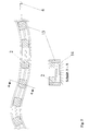
- a magnetron (with cooling system) 2 which is located in a housing, which in turn is designed as a drawing slide 9 with roller wheels 10 and is connected to a generator 6, by means of steel cables 7 on one Building part 1, for example a bridge pillar or a dam, guided from top to bottom at a defined speed. So that will allows drying in hard-to-reach places.
- a slide 9 used for drying a flat roof, large screed or foundation areas or also highway sections 1 will also be an arrangement in shape a slide 9 used.
- This slide 9 serves as Device carrier, which can be extended as required, the Magnetrone 2 with cooling system contains and is connected to the power supply. To carry out the method, this pull slide 9 is on a slideway 11 the surface to be dried moves. Taking advantage of the building fabric 1 incorporated reinforcement 12, which in this case as a reflector and This accelerates the large area in a short amount of time dried.
- Magnetrons 2 which are connected to the power supply 6, arranged. These magnetrons 2 can both all have the same frequency spectrum as well as each working with a different frequency spectrum.
Landscapes
- Engineering & Computer Science (AREA)
- Architecture (AREA)
- Microbiology (AREA)
- Life Sciences & Earth Sciences (AREA)
- Electromagnetism (AREA)
- Physics & Mathematics (AREA)
- Health & Medical Sciences (AREA)
- Biotechnology (AREA)
- Civil Engineering (AREA)
- Structural Engineering (AREA)
- Chemical & Material Sciences (AREA)
- Electrochemistry (AREA)
- Biomedical Technology (AREA)
- Water Supply & Treatment (AREA)
- Chemical Kinetics & Catalysis (AREA)
- Molecular Biology (AREA)
- Mechanical Engineering (AREA)
- General Engineering & Computer Science (AREA)
- Drying Of Solid Materials (AREA)
- Constitution Of High-Frequency Heating (AREA)
Applications Claiming Priority (3)
| Application Number | Priority Date | Filing Date | Title |
|---|---|---|---|
| DE19544889 | 1995-12-01 | ||
| DE19544889A DE19544889A1 (de) | 1995-12-01 | 1995-12-01 | Verfahren und Anordnung zur Trocknung von Gebäuden und/oder ortsfester Bauteile |
| PCT/DE1996/002231 WO1997021060A1 (de) | 1995-12-01 | 1996-11-19 | Verfahren und anordnung zur trocknung von gebäuden und/oder ortsfester bauteile |
Publications (2)
| Publication Number | Publication Date |
|---|---|
| EP0807235A1 EP0807235A1 (de) | 1997-11-19 |
| EP0807235B1 true EP0807235B1 (de) | 1999-09-22 |
Family
ID=7778959
Family Applications (1)
| Application Number | Title | Priority Date | Filing Date |
|---|---|---|---|
| EP96945890A Expired - Lifetime EP0807235B1 (de) | 1995-12-01 | 1996-11-19 | Verfahren und anordnung zur trocknung von gebäuden und/oder ortsfester bauteile |
Country Status (9)
| Country | Link |
|---|---|
| EP (1) | EP0807235B1 (da) |
| AT (1) | ATE184984T1 (da) |
| CZ (1) | CZ223997A3 (da) |
| DE (2) | DE19544889A1 (da) |
| DK (1) | DK0807235T3 (da) |
| HU (1) | HUP9800815A3 (da) |
| NO (1) | NO973110L (da) |
| RU (1) | RU2170398C2 (da) |
| WO (1) | WO1997021060A1 (da) |
Cited By (1)
| Publication number | Priority date | Publication date | Assignee | Title |
|---|---|---|---|---|
| EP1374676A2 (de) | 2002-06-17 | 2004-01-02 | Silvia Hofmann | Anordnung und Verfahrensweise zur Abtötung von holzzerstörenden Insekten und Pilzen und zur Behandlung von schadstoffbelasteten Materialien |
Families Citing this family (10)
| Publication number | Priority date | Publication date | Assignee | Title |
|---|---|---|---|---|
| SE517262C2 (sv) | 1998-04-29 | 2002-05-14 | Leif Goesta Zettergren | Förfarande för skydd mot mikrovågsstrålning vid torkning av våtskadade utrymmen |
| DE19846611A1 (de) * | 1998-10-09 | 2000-04-13 | Prozesautomation Kohler Gmbh | Mikrowellentrockner |
| DE19855555C2 (de) * | 1998-12-02 | 2001-03-15 | Linn High Therm Gmbh | Heizeinrichtung |
| ITVI20020116A1 (it) * | 2002-06-03 | 2003-12-03 | Rf Systems Srl | Dispositivo per il riscaldamento e/o l'essiccazione di superfici |
| DE20209108U1 (de) | 2002-06-12 | 2002-09-05 | Kohler, Fritz, 35510 Butzbach | Mikrowellentrockner |
| DE10248666C1 (de) | 2002-10-16 | 2003-12-24 | Hartwig Pollinger | Verfahren zur Trocknung von Booten aus Holz- und/oder Kunststoffwerkstoffen |
| RU2302592C1 (ru) * | 2005-12-15 | 2007-07-10 | Белгородский государственный технологический университет им. В.Г. Шухова | Способ свч-обработки диэлектрических материалов |
| DE102006054355A1 (de) * | 2006-11-17 | 2008-06-05 | Büsch, Werner, Dipl.-Volksw. | Verfahren und Vorrichtung zur Entfeuchtung |
| DE202010001410U1 (de) * | 2010-01-25 | 2010-05-27 | Helmholtz-Zentrum Für Umweltforschung Gmbh - Ufz | Vorrichtung zur Trocknung und Dekontamination von Mauerwerk, Beton, Holz und anderen Feststoffen |
| DE102016107550B4 (de) * | 2016-04-22 | 2021-09-16 | Helmholtz-Zentrum Für Umweltforschung Gmbh - Ufz | Verfahren und Vorrichtung zur thermischen Behandlung von Feststoffen |
Family Cites Families (14)
| Publication number | Priority date | Publication date | Assignee | Title |
|---|---|---|---|---|
| DE276330C (da) * | ||||
| JPS5344065B2 (da) * | 1974-04-17 | 1978-11-25 | ||
| FR2571201B1 (fr) * | 1984-10-02 | 1987-01-02 | Valeo | Procede de chauffage dans la masse d'une substance par exemple en vue d'une vulcanisation ou d'une polymerisation |
| DE3644920A1 (de) * | 1986-03-07 | 1987-12-23 | Bosch Siemens Hausgeraete | Mikrowellenofen |
| DE3623511A1 (de) * | 1986-07-11 | 1988-01-21 | Max Wagner | Verfahren und vorrichtung zum trocknen von keramischen hohlkoerpern |
| US4765773A (en) * | 1987-02-27 | 1988-08-23 | Hopkins Harry C | Microwave highway paint drying apparatus |
| DK86888A (da) * | 1988-02-19 | 1989-08-20 | Winterthur Borgen A S | Fremgangsmaade ved behandling af bygningskonstruktioner, der er inficeret med skadelige organismer, til uskadeliggoerelse af disse |
| DE4009691A1 (de) * | 1989-03-28 | 1990-10-04 | Gisip Inventor Ab | Lufttrocknung mittels mikrowellen und einrichtung dafuer |
| IT1245314B (it) * | 1990-06-21 | 1994-09-19 | Immobiliare Centro Nord Spa | Procedimento e forno per accelerare la stagionatura di conglomerati cementizi. |
| FR2664796A1 (fr) * | 1990-07-18 | 1992-01-24 | Moreau Sa | Procede de nettoyage de racines et tubercules, notamment de betteraves, apres leur arrachage. |
| FI945551L (fi) * | 1990-11-05 | 1994-11-25 | Elmatec Oy | Kuivauslaite |
| DE4200101A1 (de) * | 1992-01-03 | 1993-07-08 | Reinhard Schulze | Verfahren zur mikrowellenbeaufschlagung, insbesondere zum trocknen, von materialien und einrichtung zur durchfuehrung des verfahrens |
| SE502580C2 (sv) * | 1994-03-02 | 1995-11-13 | Leif Goesta Zettergren | Förfarande och anordning för mögelsanering och torkning av fuktiga byggnadsdelar |
| DE9413736U1 (de) * | 1994-06-14 | 1995-07-13 | AHRENS Bautechnologie Handelsgesellschaft mbH, 61118 Bad Vilbel | Mikrowellen-Trocknungs- und Schädlingsbekämpfungsanlage |
-
1995
- 1995-12-01 DE DE19544889A patent/DE19544889A1/de not_active Ceased
-
1996
- 1996-11-19 AT AT96945890T patent/ATE184984T1/de not_active IP Right Cessation
- 1996-11-19 DK DK96945890T patent/DK0807235T3/da active
- 1996-11-19 DE DE59603156T patent/DE59603156D1/de not_active Expired - Fee Related
- 1996-11-19 WO PCT/DE1996/002231 patent/WO1997021060A1/de not_active Ceased
- 1996-11-19 CZ CZ972239A patent/CZ223997A3/cs unknown
- 1996-11-19 HU HU9800815A patent/HUP9800815A3/hu unknown
- 1996-11-19 EP EP96945890A patent/EP0807235B1/de not_active Expired - Lifetime
- 1996-11-19 RU RU97114448/06A patent/RU2170398C2/ru active
-
1997
- 1997-07-04 NO NO973110A patent/NO973110L/no not_active Application Discontinuation
Cited By (1)
| Publication number | Priority date | Publication date | Assignee | Title |
|---|---|---|---|---|
| EP1374676A2 (de) | 2002-06-17 | 2004-01-02 | Silvia Hofmann | Anordnung und Verfahrensweise zur Abtötung von holzzerstörenden Insekten und Pilzen und zur Behandlung von schadstoffbelasteten Materialien |
Also Published As
| Publication number | Publication date |
|---|---|
| RU2170398C2 (ru) | 2001-07-10 |
| NO973110L (no) | 1997-09-26 |
| NO973110D0 (no) | 1997-07-04 |
| EP0807235A1 (de) | 1997-11-19 |
| DE59603156D1 (de) | 1999-10-28 |
| HUP9800815A2 (hu) | 1998-07-28 |
| HUP9800815A3 (en) | 2002-07-29 |
| CZ223997A3 (en) | 1997-11-12 |
| ATE184984T1 (de) | 1999-10-15 |
| WO1997021060A1 (de) | 1997-06-12 |
| DE19544889A1 (de) | 1997-06-05 |
| DK0807235T3 (da) | 2000-03-27 |
Similar Documents
| Publication | Publication Date | Title |
|---|---|---|
| EP0807235B1 (de) | Verfahren und anordnung zur trocknung von gebäuden und/oder ortsfester bauteile | |
| DE69110902T2 (de) | Trocknungsverfahren. | |
| DE69807516T2 (de) | Verfahren zur trocknung von schnittholz und vorrichtung zur durchführung des verfahrens | |
| DE69806000T2 (de) | Verfahren und v0rrichtung zum entfernen von feuchtigkeit und/oder schimmel aus einer gebäudekonstruktion | |
| DE69108988T2 (de) | Vorrichtung zur Erhärtung von Zementmischungen. | |
| DE202010001410U1 (de) | Vorrichtung zur Trocknung und Dekontamination von Mauerwerk, Beton, Holz und anderen Feststoffen | |
| WO1991019058A1 (de) | Lehmbauplatte und verfahren zu ihrer herstellung | |
| DE69503610T2 (de) | Mobiler mikrowellentrockner | |
| DE4316901A1 (de) | Dämmstoff sowie Verfahren und Vorrichtung zu dessen Herstellung | |
| DE3306044C2 (da) | ||
| WO2015132197A1 (de) | Trocknungsvorrichtung | |
| WO1994008767A1 (de) | Verfahren zur herstellung von verbundplatten | |
| DE10008332C1 (de) | Dämmstoffmaterial zum klemmenden Einbau zwischen Begrenzungen | |
| DE69916447T2 (de) | Abschirmmittel für mikrowellen | |
| DE3504873C2 (da) | ||
| AT405845B (de) | Verfahren zur herstellung einer mineralfaserlamellenbahn und vorrichtung zur durchführung des verfahrens | |
| DE2502524A1 (de) | Verfahren und vorrichtung zur thermischen behandlung von gegenstaenden mittels eines hochfrequenten elektrischen feldes | |
| DE3418101A1 (de) | Verfahren zur behandlung von wasserhaltigen substanzen und einrichtung zur durchfuehrung des verfahrens | |
| DE102018105385B4 (de) | Durchlaufofen und Anlage zur Herstellung von Holzwerkstoffplatten | |
| DE19702843C1 (de) | Verfahren zur Herstellung eines folienfreien Dämmstoffes aus Holzabfällen, insbesondere aus Hobelspänen sowie Anlage zur Durchführung des Verfahrens | |
| DE68902831T2 (de) | Vorrichtung zur trocknung von furnier und sonstigen erzeug- nissen. | |
| EP0563536A1 (de) | Isolierkörper und Verfahren zur Herstellung desselben | |
| EP1390262B1 (de) | Verfahren zur herstellung einer verpackungs- und/oder transporteinheit für plattenförmige dämmstoffe aus mineralfasern, verpackungs- und/oder transporteinheit sowie dämmstoffplatte | |
| DE102018105390B4 (de) | Durchlaufofen und Anlage zur Herstellung von Holzwerkstoffplatten | |
| EP4231780A1 (de) | Vorrichtung zur kontrollierten erwärmung von formkörpern |
Legal Events
| Date | Code | Title | Description |
|---|---|---|---|
| PUAI | Public reference made under article 153(3) epc to a published international application that has entered the european phase |
Free format text: ORIGINAL CODE: 0009012 |
|
| 17P | Request for examination filed |
Effective date: 19970805 |
|
| AK | Designated contracting states |
Kind code of ref document: A1 Designated state(s): AT BE CH DE DK FI FR IT LI LU NL SE |
|
| 17Q | First examination report despatched |
Effective date: 19981026 |
|
| GRAG | Despatch of communication of intention to grant |
Free format text: ORIGINAL CODE: EPIDOS AGRA |
|
| GRAG | Despatch of communication of intention to grant |
Free format text: ORIGINAL CODE: EPIDOS AGRA |
|
| GRAH | Despatch of communication of intention to grant a patent |
Free format text: ORIGINAL CODE: EPIDOS IGRA |
|
| GRAH | Despatch of communication of intention to grant a patent |
Free format text: ORIGINAL CODE: EPIDOS IGRA |
|
| GRAA | (expected) grant |
Free format text: ORIGINAL CODE: 0009210 |
|
| AK | Designated contracting states |
Kind code of ref document: B1 Designated state(s): AT BE CH DE DK FI FR IT LI LU NL SE |
|
| REF | Corresponds to: |
Ref document number: 184984 Country of ref document: AT Date of ref document: 19991015 Kind code of ref document: T |
|
| REG | Reference to a national code |
Ref country code: CH Ref legal event code: EP |
|
| REF | Corresponds to: |
Ref document number: 59603156 Country of ref document: DE Date of ref document: 19991028 |
|
| ITF | It: translation for a ep patent filed | ||
| REG | Reference to a national code |
Ref country code: CH Ref legal event code: NV Representative=s name: BOVARD AG PATENTANWAELTE |
|
| ET | Fr: translation filed | ||
| REG | Reference to a national code |
Ref country code: DK Ref legal event code: T3 |
|
| PLBE | No opposition filed within time limit |
Free format text: ORIGINAL CODE: 0009261 |
|
| STAA | Information on the status of an ep patent application or granted ep patent |
Free format text: STATUS: NO OPPOSITION FILED WITHIN TIME LIMIT |
|
| 26N | No opposition filed | ||
| REG | Reference to a national code |
Ref country code: CH Ref legal event code: PUE Owner name: STEINBACH, DETLEF TRANSFER- ASTON AG |
|
| REG | Reference to a national code |
Ref country code: FR Ref legal event code: TP |
|
| NLS | Nl: assignments of ep-patents |
Owner name: ASTON AG |
|
| PGFP | Annual fee paid to national office [announced via postgrant information from national office to epo] |
Ref country code: FI Payment date: 20010927 Year of fee payment: 6 |
|
| PGFP | Annual fee paid to national office [announced via postgrant information from national office to epo] |
Ref country code: FR Payment date: 20010928 Year of fee payment: 6 |
|
| PGFP | Annual fee paid to national office [announced via postgrant information from national office to epo] |
Ref country code: DE Payment date: 20010929 Year of fee payment: 6 |
|
| PGFP | Annual fee paid to national office [announced via postgrant information from national office to epo] |
Ref country code: LU Payment date: 20011030 Year of fee payment: 6 Ref country code: AT Payment date: 20011030 Year of fee payment: 6 |
|
| PGFP | Annual fee paid to national office [announced via postgrant information from national office to epo] |
Ref country code: CH Payment date: 20011109 Year of fee payment: 6 |
|
| PGFP | Annual fee paid to national office [announced via postgrant information from national office to epo] |
Ref country code: BE Payment date: 20011121 Year of fee payment: 6 |
|
| PGFP | Annual fee paid to national office [announced via postgrant information from national office to epo] |
Ref country code: NL Payment date: 20011123 Year of fee payment: 6 |
|
| PGFP | Annual fee paid to national office [announced via postgrant information from national office to epo] |
Ref country code: DK Payment date: 20011127 Year of fee payment: 6 |
|
| PGFP | Annual fee paid to national office [announced via postgrant information from national office to epo] |
Ref country code: SE Payment date: 20011128 Year of fee payment: 6 |
|
| PG25 | Lapsed in a contracting state [announced via postgrant information from national office to epo] |
Ref country code: LU Free format text: LAPSE BECAUSE OF NON-PAYMENT OF DUE FEES Effective date: 20021119 Ref country code: FI Free format text: LAPSE BECAUSE OF NON-PAYMENT OF DUE FEES Effective date: 20021119 Ref country code: AT Free format text: LAPSE BECAUSE OF NON-PAYMENT OF DUE FEES Effective date: 20021119 |
|
| PG25 | Lapsed in a contracting state [announced via postgrant information from national office to epo] |
Ref country code: SE Free format text: LAPSE BECAUSE OF NON-PAYMENT OF DUE FEES Effective date: 20021120 |
|
| PG25 | Lapsed in a contracting state [announced via postgrant information from national office to epo] |
Ref country code: LI Free format text: LAPSE BECAUSE OF NON-PAYMENT OF DUE FEES Effective date: 20021130 Ref country code: CH Free format text: LAPSE BECAUSE OF NON-PAYMENT OF DUE FEES Effective date: 20021130 Ref country code: BE Free format text: LAPSE BECAUSE OF NON-PAYMENT OF DUE FEES Effective date: 20021130 |
|
| PG25 | Lapsed in a contracting state [announced via postgrant information from national office to epo] |
Ref country code: DK Free format text: LAPSE BECAUSE OF NON-PAYMENT OF DUE FEES Effective date: 20021231 |
|
| BERE | Be: lapsed |
Owner name: *STEINBACH DETLEF Effective date: 20021130 |
|
| PG25 | Lapsed in a contracting state [announced via postgrant information from national office to epo] |
Ref country code: NL Free format text: LAPSE BECAUSE OF NON-PAYMENT OF DUE FEES Effective date: 20030601 |
|
| PG25 | Lapsed in a contracting state [announced via postgrant information from national office to epo] |
Ref country code: DE Free format text: LAPSE BECAUSE OF NON-PAYMENT OF DUE FEES Effective date: 20030603 |
|
| EUG | Se: european patent has lapsed | ||
| REG | Reference to a national code |
Ref country code: DK Ref legal event code: EBP |
|
| REG | Reference to a national code |
Ref country code: CH Ref legal event code: PL |
|
| PG25 | Lapsed in a contracting state [announced via postgrant information from national office to epo] |
Ref country code: FR Free format text: LAPSE BECAUSE OF NON-PAYMENT OF DUE FEES Effective date: 20030731 |
|
| NLV4 | Nl: lapsed or anulled due to non-payment of the annual fee |
Effective date: 20030601 |
|
| REG | Reference to a national code |
Ref country code: FR Ref legal event code: ST |
|
| PG25 | Lapsed in a contracting state [announced via postgrant information from national office to epo] |
Ref country code: IT Free format text: LAPSE BECAUSE OF NON-PAYMENT OF DUE FEES Effective date: 20051119 |