EP0807311B1 - Dispositif de regulation de tension - Google Patents
Dispositif de regulation de tension Download PDFInfo
- Publication number
- EP0807311B1 EP0807311B1 EP96902973A EP96902973A EP0807311B1 EP 0807311 B1 EP0807311 B1 EP 0807311B1 EP 96902973 A EP96902973 A EP 96902973A EP 96902973 A EP96902973 A EP 96902973A EP 0807311 B1 EP0807311 B1 EP 0807311B1
- Authority
- EP
- European Patent Office
- Prior art keywords
- voltage
- switching element
- section
- turns
- transformer
- Prior art date
- Legal status (The legal status is an assumption and is not a legal conclusion. Google has not performed a legal analysis and makes no representation as to the accuracy of the status listed.)
- Expired - Lifetime
Links
- 238000004804 winding Methods 0.000 claims abstract description 52
- 230000007935 neutral effect Effects 0.000 claims description 20
- 239000004020 conductor Substances 0.000 claims description 17
- 238000009434 installation Methods 0.000 claims description 8
- 230000003247 decreasing effect Effects 0.000 description 5
- 238000000034 method Methods 0.000 description 3
- 238000010079 rubber tapping Methods 0.000 description 3
- XEEYBQQBJWHFJM-UHFFFAOYSA-N Iron Chemical group [Fe] XEEYBQQBJWHFJM-UHFFFAOYSA-N 0.000 description 2
- 206010028347 Muscle twitching Diseases 0.000 description 2
- 238000011144 upstream manufacturing Methods 0.000 description 2
- PMVSDNDAUGGCCE-TYYBGVCCSA-L Ferrous fumarate Chemical group [Fe+2].[O-]C(=O)\C=C\C([O-])=O PMVSDNDAUGGCCE-TYYBGVCCSA-L 0.000 description 1
- 241000566137 Sagittarius Species 0.000 description 1
- 238000010276 construction Methods 0.000 description 1
- 230000036461 convulsion Effects 0.000 description 1
- 230000001419 dependent effect Effects 0.000 description 1
- 230000000694 effects Effects 0.000 description 1
- 230000005611 electricity Effects 0.000 description 1
- 238000005516 engineering process Methods 0.000 description 1
- 230000001105 regulatory effect Effects 0.000 description 1
- 230000009466 transformation Effects 0.000 description 1
Images


Classifications
-
- H—ELECTRICITY
- H01—ELECTRIC ELEMENTS
- H01F—MAGNETS; INDUCTANCES; TRANSFORMERS; SELECTION OF MATERIALS FOR THEIR MAGNETIC PROPERTIES
- H01F30/00—Fixed transformers not covered by group H01F19/00
- H01F30/02—Auto-transformers
-
- H—ELECTRICITY
- H01—ELECTRIC ELEMENTS
- H01F—MAGNETS; INDUCTANCES; TRANSFORMERS; SELECTION OF MATERIALS FOR THEIR MAGNETIC PROPERTIES
- H01F29/00—Variable transformers or inductances not covered by group H01F21/00
- H01F29/02—Variable transformers or inductances not covered by group H01F21/00 with tappings on coil or winding; with provision for rearrangement or interconnection of windings
Definitions
- the invention relates to a lighting system with gas discharge lamps and an autotransformer uninterrupted voltage regulation of the Gas discharge lamps.
- a street lighting system will be used during the evening rush hour generally with full Luminous intensity, i.e. operated with mains voltage, and in the quiet night time with reduced tension. With gas discharge lamps, switching from the Mains voltage to the reduced voltage and vice versa uninterrupted, otherwise the lamp will fail.
- this is stepless adjustable transformers used, e.g. B. a Autotransformer that has an iron core with only one Has winding, the input side with the phase of Network and the neutral conductor and on the output side with one Tapping the transformer winding and the neutral conductor connected is.
- the voltage to be removed is indicated by Tap the line leading to the phase of the consumer leads, obtained on a turn of the winding.
- the Ratio of the voltage to be reduced to the nominal voltage corresponds to the ratio of the number of turns, between the output side of the winding and of the stripped turn to the total number the winding of the winding.
- the entire winding forms so the primary winding, during the winding section between the tap and the neutral Secondary winding of the savings transformer forms.
- Designated load section is also called Designated load section.
- variable transformers are known in which the Winding is provided with taps. So while there is no interruption of switching and no short circuit of the turns to be switched on and off occurs in each branch between tapping and the supply line to the consumer two switching elements provided, the second switching element a Resistance bridged. The switching process begins with the fact that in the connected, first branch of the Resistor is turned on and then over an equal resistance in the other branch Connection is made with the new tap. The turns to be switched between the two Taps are now short-circuited in the Short circuit, however, are the two resistors and limit the short-circuit current. If so now first switching element is separated in the first branch, the new tap is already connected. Your direct connection to the outer supply line finally by closing the second switching element in the second branch reached.
- the well-known variable transformer with tap changer is through the two switching elements and the resistance at each tap is expensive and accordingly expensive.
- the object of the invention is a simple structure To provide lighting system with gas discharge lamps, which is an uninterrupted voltage regulation of gas discharge lamps.
- the device according to the invention is preferably used for Bridging the load section of the transformer and the other switching element, the primary winding except To put operation. It can also be in the control section be provided.
- the two Switching elements When switching to change the Voltage on the gas discharge lamps are the two Switching elements controlled so that the load section Throttle forms. In this way, the Gas discharge lamps when switching always with the Minimum voltage supplied. When switching between individual switching elements practically simultaneously takes place, the throttling effect can hardly bear come. The short circuit can then be so short that the short-circuit current cannot increase.
- the Switching elements can therefore be controlled so that a Short circuit is limited in time so that a Damage to the switching elements or lines is prevented.
- controllable transformer there is the primary and / or Secondary winding preferably at least partly from individual sections, which in one of the combination corresponding to decreasing voltage are interconnectable.
- At least one section has the first switching element in its current path and the other between its entrance and the exit Switching element on.
- the switching elements are preferred by Sagittarius formed.
- Each section can have one Resistor, a choke and / or a fuse have, preferably a line with the one Switching element is provided with which the consumer the phase of the network can be connected.
- the further Switching element can be arranged in the line, which the load section on the output side with the consumer connects.
- the transformer winding of the autotransformer has preferably one on the input side to the phase of Network and output side to the phase of the consumer connected load section and one connected on the output side to the neutral conductor Control section on, which at least partially from the Individual sections that exist in one of the combination with decreasing voltage the neutral are connectable.
- the tax section consists preferably of a first part and a second part. The second part is between the arranged first part and the load section. It is the number of turns connected to the neutral conductor of the second part unchangeable, while the number of turns of the first which can be connected to the neutral conductor Is partly changeable.
- the consumer is one Lighting system with gas discharge lamps.
- the gas discharge lamps at full light intensity So operating with mains voltage is the first Switching element closed and the second switching element open. If the Brightness reduced, that is Gear ratio of the transformer corresponding voltage drop, the first switching element opened and the second switching element getting closed. To do this is a certain one Switchover time necessary.
- the two switching elements are preferably by protection with make contacts and / or protection with make and break contacts. At protection as a switching element is the switchover time a few milliseconds.
- a switching element in the primary circuit opened So that goes the load section of the transformer, i.e. the Section over which the load current flows into a Throttle over. This way a failure of the Lamp prevented during the switching process. Then the further switching element is closed, whereby a the transformation ratio of the transformer sets the corresponding voltage drop.
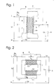
- FIGS. 1 to 5 a different circuit of an autotransformer show according to the invention.
- the autotransformer consists of a closed iron core 1 with a winding 2. Die entire winding 2 forms the primary winding of the Autotransformer, section 4 of winding 2 between phase L of the network and tap 3 of the Line 5 to the gas discharge lamp 6 provides the The load section represents the load current IL to the lamp 6 flows.
- the winding section 7 between the tap 3 and the neutral conductor N forms the secondary winding of the Autotransformer through which the magnetizing current IM and a compensation current dependent on the load flows.
- the phase L of the network is via a bypass line 8 connected to line 5.
- the bypass line 8 has a first switching element 9, so that they at closed switching element 9 the load section 4th bridged.
- the output of the secondary winding 7 is with the neutral conductor N connected via a line 10, the one has second switching element 11.
- the two switching elements 9 and 11 are by a Contactor, i.e. a remote-controlled electromagnetic Switch formed, preferably by the closer or opener of the same contactor, or by the two NO contacts of a contactor, as in the drawing shown.
- a Contactor i.e. a remote-controlled electromagnetic Switch formed, preferably by the closer or opener of the same contactor, or by the two NO contacts of a contactor, as in the drawing shown.
- the nominal voltage is designated U1, and the Load voltage with U2.
- the switching element 9 opens and the switching element 11 is closed, that is at unactuated contactor, the lamp 6 with the by Transformer reduced voltage U2 ⁇ U1 operated.
- the contactor is actuated.
- the load section 4 acts during the switching time of Protection for a short time, d. H. for example 5 to 50 Milliseconds as a choke.
- the throttle leads to a voltage drop. However, this is low, so that the lamp 6 during the switching process with a sufficient voltage U2 is supplied.
- closes the switching element 9, whereby the load section 4th or bridged the choke and thus the lamp 6 with the nominal voltage U1 is operated, that is U2 U1.
- the nominal voltage z. B. is 220 V
- the reduced voltage U2 is greater is than that for operating the gas discharge lamp 6 required minimum voltage, preferably 5 V to 10 V greater than the minimum voltage to accommodate fluctuations in the Nominal voltage.
- the load section 4 is the Bridged transformer and the primary winding 2 or the control section 7 is deactivated.
- the two switching elements 9, 11 are each so controlled that the load section 4 a Gas discharge lamps 6 forms upstream choke.
- FIG. 2 shows a transformer with a primary winding 12 and a secondary winding 13 on a closed one Iron core 1 shown. Through lines 15 and 16 this transformer is also switched as an economy transformer.
- the secondary winding 13 forms the load section of the Transformer, i.e. the section over which the Load current IL flows via line 14 to lamp 6.
- the secondary winding 13 has a bypass line 8 can be bridged with a first switching element 9.
- the primary winding 12 is on the input side with the phase L of the network connected via a line 15 in which the second switching element 11 is arranged.
- the exit side the primary winding 12 is connected via a line 16 to the Neutral conductor N connected.
- the switching element 9 When the load voltage U2 to a reduced voltage U2 ⁇ U1 is to be switched, the switching element 9 first opened so that the secondary winding 13 as Throttle acts, whereupon the switching element 11 is closed becomes.
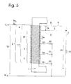
- FIG. 1 An autotransformer is shown in FIG which the load voltage U2 can be finely regulated can.
- the secondary winding 7 of Figure 1 is there replaced by a control section 17.
- the control section 17 is composed of a first part 18 and a second part 19 is formed.
- the turns of the second part 19 connect to the turns of the Load section 4.
- the turns of the first part 18 the control section 17 consist of several Sections I to IV.
- Each individual section I to IV points in its current path a first switching element 24 to 27. Furthermore, a Switching element 28 to 31 between the input side E and the output side A of each section I to IV intended. From the input side E each Section I to IV leads a line 32 to 35 to the turns of the relevant section I to IV, with the first in lines 32 to 35 Switching element 24 to 27 is arranged. Another Line 36 to 39 leads from the turns of the each individual section I to IV to the Output side A of the same.
- the input side E of the first individual section I is via a line 40 to the output side of the second Part 19 of the control section 17 connected while the output side A of the facing away from the second part 19 Section IV via a line 41 with the Neutral conductor N is connected, in line 41 that Switching element 11 is arranged.
- a line 40 to the output side of the second Part 19 of the control section 17 connected while the output side A of the facing away from the second part 19 Section IV via a line 41 with the Neutral conductor N is connected, in line 41 that Switching element 11 is arranged.
- the Switching elements 28 to 31 are the Switching elements 28 to 31.
- Each individual section I to IV has one different number of turns. For example, can the individual section I ten, the individual section II twenty, section III forty and the Individual section IV have eighty turns.
- the number of turns NM of the Control section 17, which is connected to the neutral conductor are in accordance with the voltage U2 to be taken be changed.
- the number of turns NM of the The control section consists of the unchangeable Number of turns NM const. Of the second part 19 and changeable number of turns NM v of the individual sections I to IV, which are connected to the neutral conductor N.
- the voltage to be decreased U2 for all connected four individual sections I to IV z. B. 210 V and the decreasing voltage U2 for all four switched off Individual sections I to IV, i.e. only with the turns of the second part 19 of the control section 17 z. B. 170 V the voltage U2 can be between 170 V and 210 V can be changed in sixteen steps.
- the change in voltage at each stage is but not the same size. That is, it exists no linearity between the switched on Number of turns and change in size of the decreasing voltage U2.
- NR NL x U2 (U1-U2) - NF
- NL is the number of turns of the load section 4
- U1 the nominal voltage
- NF the unchangeable number of turns of the second part 19 of the control section 17.
- the total effective winding, i.e. H. the load section 4, the second part 19 of the control section 17 with the invariable number of turns NF as well as the switched turns NR of the first part 18 of the Control section 17 form the primary winding of the Saving transformers, while the second part 19 and the switched turns NR of the first part 18 die Form secondary winding. It can be seen that with that the primary and secondary winding for the economy transformer can be changed, depending on which Section I to IV interconnected and with the Neutral conductor N are connected.
- the transformer can also be designed in three phases.
- the first switching element 24 to 27 and the second switching element 28 to 31 the individual section I until IV are closed at the same time individual sections I to IV short-circuited, so that it can be destroyed.
- switching elements 24 up to 31 can shooters, remote controlled electromagnetic switches are used that are inexpensive and millions of switches withstand.
- the two switching elements 24 and 28, 25 and 29, 26 and 30 and 27 and 31 of each section I to IV should switch on the one hand if possible, so that the twitching stops, on the other hand they are allowed not be closed at the same time because otherwise a Short circuit occurs.
- the short-circuit current however, needs a certain one Time from z. B. two to ten milliseconds until it turns fully built. Therefore, when switching elements 24 to 31 be used which have a very short switching time have, for example, a switching time that the Half or less of the build time for the Short-circuit current, there is a risk that a Short circuit to damage the concerned Section I to IV leads, significantly reduced.
- the primary winding is 12 in the same way from individual sections I to IV constructed like the first part 18 of the control section 17 of the autotransformer according to FIG. 3. Accordingly, in Figure 4 also the same reference numerals for the Switching elements 24 to 31, the lines 32 to 39 and the resistor 43 used.
- the switching element 11 is in the line 16 arranged which the output of the Individual section IV connects to the neutral conductor N. This transformer is through lines 15 and 16 also switched as an economy transformer.
- Control section 17 of the savings transformer several branches 53, 54, 55 on, which by the switching elements 50, 51, 52, preferably contactors, optionally with neutral line N are connectable.
Landscapes
- Engineering & Computer Science (AREA)
- Power Engineering (AREA)
- Control Of Electrical Variables (AREA)
- Details Of Television Scanning (AREA)
- Investigating, Analyzing Materials By Fluorescence Or Luminescence (AREA)
- Control Of Eletrric Generators (AREA)
- Circuit Arrangements For Discharge Lamps (AREA)
- Ac-Ac Conversion (AREA)
Claims (7)
- Système d'éclairage comportant des lampes luminescentes à gaz (6) et un autotransformateur pour le réglage sans interruption de la tension des lampes luminescentes à gaz (6), caractérisé par au moins un organe de commutation (11 ; 50) dans le circuit primaire (2 ; 12) destiné à mettre hors service la fonction de transformateur et au moins un autre organe de commutation (9, 24 à 31 ; 51, 52) dans le circuit primaire (2 ; 12) ou parallèlement au segment de charge (4 ; 13) du transformateur, les organes de commutation (9, 11 ; 24 à 31 ; 50, 51, 52) étant commandés de telle sorte lors de la commutation dans le but de varier la tension (U2) appliquée aux lampes luminescentes à gaz (6), que le segment de charge (4 ; 13) fonctionne comme un self.
- Système d'éclairage selon la revendication 1, caractérisé en ce que les organes de commutation (9, 11 ; 24 à 31 ; 50 à 52) sont formés par un contacteur-disjoncteur.
- Système d'éclairage selon les revendications 1 ou 2, caractérisé en ce que les circuits primaire et/ou secondaire (2, 12 ; 13) de l'autotransformateur sont constitués au moins partiellement par des segments individuels (I à IV) qui sont susceptibles d'être interconnectés dans une combinaison correspondant à la tension (U2) appliquée au consommateur (6).
- Système d'éclairage selon les revendications 1 et 3, caractérisé en ce que chaque segment individuel (I à IV) dans le circuit primaire (2) présente deux autres organes de commutation (24 à 31), le premier organe de commutation (24 à 27) étant prévu dans le trajet du courant du segment individuel (I à IV) et le second organe de commutation (28 à 31) étant prévu entre l'entrée (E) et la sortie (A) du segment individuel (I à IV).
- Système d'éclairage selon l'une quelconque des revendications précédentes, caractérisé en ce que chaque segment individuel (I à IV) présente une résistance, un self (43) et/ou un fusible de sécurité.
- Système d'éclairage selon l'une quelconque des revendications précédentes, caractérisé en ce que l'enroulement de l'autotransformateur présente un segment de charge (4) branché côté entrée à la phase (L) du réseau et côté sortie à la phase des lampes luminescentes à gaz (6), et un segment de commande (17) relié côté sortie au conducteur neutre (N), lequel est constitué au moins partiellement par les segments individuels (I à IV) qui sont susceptibles d'être reliés au conducteur neutre (N) dans une combinaison correspondant à la tension (U2) appliquée aux lampes luminescentes à gaz (6).
- Système d'éclairage selon la revendication 6, caractérisé en ce que le segment de commande (17) est constitué par une première partie (18) et par une seconde partie (19) située entre la première partie (18) et le segment de charge (4), le nombre des spires de la seconde partie (19) reliées au conducteur neutre (N) étant invariable et le nombre de spires de la première partie (18) reliées au conducteur neutre (N) étant variable.
Applications Claiming Priority (7)
| Application Number | Priority Date | Filing Date | Title |
|---|---|---|---|
| DE19503379 | 1995-02-02 | ||
| DE19503379 | 1995-02-02 | ||
| DE19541341 | 1995-11-06 | ||
| DE19541341A DE19541341C2 (de) | 1995-02-02 | 1995-11-06 | Transformator |
| DE19543249A DE19543249A1 (de) | 1995-02-02 | 1995-11-20 | Vorrichtung zur Leistungsregelung von Gasentladungslampen |
| DE19543249 | 1995-11-20 | ||
| PCT/EP1996/000428 WO1996024146A1 (fr) | 1995-02-02 | 1996-02-01 | Dispositif de regulation de tension |
Publications (2)
| Publication Number | Publication Date |
|---|---|
| EP0807311A1 EP0807311A1 (fr) | 1997-11-19 |
| EP0807311B1 true EP0807311B1 (fr) | 1998-12-02 |
Family
ID=27214799
Family Applications (1)
| Application Number | Title | Priority Date | Filing Date |
|---|---|---|---|
| EP96902973A Expired - Lifetime EP0807311B1 (fr) | 1995-02-02 | 1996-02-01 | Dispositif de regulation de tension |
Country Status (5)
| Country | Link |
|---|---|
| EP (1) | EP0807311B1 (fr) |
| AT (1) | ATE174152T1 (fr) |
| AU (1) | AU4717396A (fr) |
| HU (1) | HUP9702427A3 (fr) |
| WO (1) | WO1996024146A1 (fr) |
Cited By (1)
| Publication number | Priority date | Publication date | Assignee | Title |
|---|---|---|---|---|
| US8723440B2 (en) | 2010-01-26 | 2014-05-13 | Gradix Holdings Ltd. | AC voltage reduction by means of a transformer |
Families Citing this family (2)
| Publication number | Priority date | Publication date | Assignee | Title |
|---|---|---|---|---|
| DE19831603A1 (de) * | 1998-07-14 | 2000-02-17 | Werner Hanke | Schaltungsvorrichtung zur annähernd sinusförmigen Absenkung einer Wechselspannung |
| EP2107861A1 (fr) * | 2008-04-01 | 2009-10-07 | BLOCK Transformatoren-Elektronik GmbH & Co. KG | Agencement de commutation destiné à réduire la tension |
Family Cites Families (3)
| Publication number | Priority date | Publication date | Assignee | Title |
|---|---|---|---|---|
| JPS58159676A (ja) * | 1981-11-30 | 1983-09-22 | Ebara Densan:Kk | 電動機の起動方法 |
| JPS60167683A (ja) * | 1984-02-08 | 1985-08-31 | Mitsubishi Electric Corp | 電源装置 |
| JPH077978A (ja) * | 1993-06-17 | 1995-01-10 | Meidensha Corp | 電動機のコンドルファ起動方式 |
-
1996
- 1996-02-01 AU AU47173/96A patent/AU4717396A/en not_active Abandoned
- 1996-02-01 HU HU9702427A patent/HUP9702427A3/hu unknown
- 1996-02-01 EP EP96902973A patent/EP0807311B1/fr not_active Expired - Lifetime
- 1996-02-01 AT AT96902973T patent/ATE174152T1/de active
- 1996-02-01 WO PCT/EP1996/000428 patent/WO1996024146A1/fr not_active Ceased
Cited By (1)
| Publication number | Priority date | Publication date | Assignee | Title |
|---|---|---|---|---|
| US8723440B2 (en) | 2010-01-26 | 2014-05-13 | Gradix Holdings Ltd. | AC voltage reduction by means of a transformer |
Also Published As
| Publication number | Publication date |
|---|---|
| WO1996024146A1 (fr) | 1996-08-08 |
| ATE174152T1 (de) | 1998-12-15 |
| HUP9702427A2 (hu) | 1998-03-30 |
| AU4717396A (en) | 1996-08-21 |
| HUP9702427A3 (en) | 1999-11-29 |
| EP0807311A1 (fr) | 1997-11-19 |
Similar Documents
| Publication | Publication Date | Title |
|---|---|---|
| DE102012107446B4 (de) | Lastumschalter, Laststufenschalter und Verfahren zum Umschalten eines Laststufenschalters | |
| AT411938B (de) | Verfahren und vorrichtung zur regelung der elektrischen spannung in elektrischen versorgungsnetzen und/oder verbraucheranlagen | |
| DE639192C (de) | Einrichtung zur Speisung elektrischer Verbraucher | |
| DE19541341C2 (de) | Transformator | |
| AT501582B1 (de) | Verfahren zur regelung der elektrischen spannung in elektrischen versorgungsnetzen sowie einrichtung zur durchführung des verfahrens | |
| DE4309484C1 (de) | Verfahren zum Unterdrücken eines Einschaltstromstoßes beim Anschalten eines Leistungstransformators | |
| DE19747712C2 (de) | Anordnung eines Stufenschalters an einem Stufentransformator | |
| EP0807311A1 (fr) | Dispositif de regulation de tension | |
| EP3365906A1 (fr) | Transformateur de réseau de répartition réglable | |
| DE19947285A1 (de) | Vorrichtung zur Steuerung der elektrischen Spannung an einem Verbraucher | |
| EP0069284B1 (fr) | Dispositif de connexions pour bobinages dans les transformateurs de double étage | |
| EP3419389B1 (fr) | Commande de phase realisée par interruption | |
| EP0746184A2 (fr) | Circuit d'alimentation de charges électriques permettant des économies d'énergie | |
| EP0978131A1 (fr) | Circuit pour un commutateur de reglage en charge | |
| DE3104676C2 (de) | Beleuchtungsanlage mit Gasentladungslampen, die mit Vorschaltdrosseln versehen sind | |
| DE102006050624A1 (de) | Reaktanzvorschalteinrichtung | |
| DE3502889C2 (fr) | ||
| DE2804564B2 (de) | Schaltung zur Lichtstromänderung bei Quecksilberdampf- oder Natriumdampf-Hochdrucklampen | |
| EP2107861A1 (fr) | Agencement de commutation destiné à réduire la tension | |
| EP1016204B1 (fr) | Circuit destine a l'abaissement presque sinusoidal d'une tension alternative | |
| DE3038561A1 (de) | Hochspanungsschalter mit mindestens zwei unterschiedlich beschalteten schaltstrecken | |
| DE29818018U1 (de) | Schaltungsanordnung zum energiesparenden Betrieb von elektrischen Verbrauchern | |
| DE2532968C2 (fr) | ||
| DE19718127A1 (de) | Schaltungsanordnung zum Einstellen einer Wechselstromverbraucherspannung | |
| DE3823024A1 (de) | Einrichtung zur spannungsumschaltung einer windung eines in sternschaltung geschalteten drehstrom-spartransformators |
Legal Events
| Date | Code | Title | Description |
|---|---|---|---|
| PUAI | Public reference made under article 153(3) epc to a published international application that has entered the european phase |
Free format text: ORIGINAL CODE: 0009012 |
|
| 17P | Request for examination filed |
Effective date: 19970801 |
|
| AK | Designated contracting states |
Kind code of ref document: A1 Designated state(s): AT DE ES FR GB IT NL SE |
|
| 17Q | First examination report despatched |
Effective date: 19971113 |
|
| GRAG | Despatch of communication of intention to grant |
Free format text: ORIGINAL CODE: EPIDOS AGRA |
|
| GRAG | Despatch of communication of intention to grant |
Free format text: ORIGINAL CODE: EPIDOS AGRA |
|
| GRAH | Despatch of communication of intention to grant a patent |
Free format text: ORIGINAL CODE: EPIDOS IGRA |
|
| GRAH | Despatch of communication of intention to grant a patent |
Free format text: ORIGINAL CODE: EPIDOS IGRA |
|
| GRAA | (expected) grant |
Free format text: ORIGINAL CODE: 0009210 |
|
| AK | Designated contracting states |
Kind code of ref document: B1 Designated state(s): AT DE ES FR GB IT NL SE |
|
| PG25 | Lapsed in a contracting state [announced via postgrant information from national office to epo] |
Ref country code: NL Free format text: LAPSE BECAUSE OF FAILURE TO SUBMIT A TRANSLATION OF THE DESCRIPTION OR TO PAY THE FEE WITHIN THE PRESCRIBED TIME-LIMIT Effective date: 19981202 Ref country code: IT Free format text: LAPSE BECAUSE OF FAILURE TO SUBMIT A TRANSLATION OF THE DESCRIPTION OR TO PAY THE FEE WITHIN THE PRE;WARNING: LAPSES OF ITALIAN PATENTS WITH EFFECTIVE DATE BEFORE 2007 MAY HAVE OCCURRED AT ANY TIME BEFORE 2007. THE CORRECT EFFECTIVE DATE MAY BE DIFFERENT FROM THE ONE RECORDED.SCRIBED TIME-LIMIT Effective date: 19981202 Ref country code: GB Free format text: LAPSE BECAUSE OF NON-PAYMENT OF DUE FEES Effective date: 19981202 Ref country code: FR Free format text: LAPSE BECAUSE OF FAILURE TO SUBMIT A TRANSLATION OF THE DESCRIPTION OR TO PAY THE FEE WITHIN THE PRESCRIBED TIME-LIMIT Effective date: 19981202 Ref country code: ES Free format text: THE PATENT HAS BEEN ANNULLED BY A DECISION OF A NATIONAL AUTHORITY Effective date: 19981202 |
|
| REF | Corresponds to: |
Ref document number: 174152 Country of ref document: AT Date of ref document: 19981215 Kind code of ref document: T |
|
| REF | Corresponds to: |
Ref document number: 59600910 Country of ref document: DE Date of ref document: 19990114 |
|
| PG25 | Lapsed in a contracting state [announced via postgrant information from national office to epo] |
Ref country code: SE Free format text: LAPSE BECAUSE OF FAILURE TO SUBMIT A TRANSLATION OF THE DESCRIPTION OR TO PAY THE FEE WITHIN THE PRESCRIBED TIME-LIMIT Effective date: 19990302 |
|
| EN | Fr: translation not filed | ||
| NLV1 | Nl: lapsed or annulled due to failure to fulfill the requirements of art. 29p and 29m of the patents act | ||
| GBV | Gb: ep patent (uk) treated as always having been void in accordance with gb section 77(7)/1977 [no translation filed] |
Effective date: 19981202 |
|
| PLBE | No opposition filed within time limit |
Free format text: ORIGINAL CODE: 0009261 |
|
| STAA | Information on the status of an ep patent application or granted ep patent |
Free format text: STATUS: NO OPPOSITION FILED WITHIN TIME LIMIT |
|
| 26N | No opposition filed | ||
| PGFP | Annual fee paid to national office [announced via postgrant information from national office to epo] |
Ref country code: DE Payment date: 20120221 Year of fee payment: 17 |
|
| REG | Reference to a national code |
Ref country code: DE Ref legal event code: R119 Ref document number: 59600910 Country of ref document: DE Effective date: 20130903 |
|
| PG25 | Lapsed in a contracting state [announced via postgrant information from national office to epo] |
Ref country code: DE Free format text: LAPSE BECAUSE OF NON-PAYMENT OF DUE FEES Effective date: 20130903 |
|
| PGFP | Annual fee paid to national office [announced via postgrant information from national office to epo] |
Ref country code: AT Payment date: 20150116 Year of fee payment: 20 |
|
| REG | Reference to a national code |
Ref country code: AT Ref legal event code: MK07 Ref document number: 174152 Country of ref document: AT Kind code of ref document: T Effective date: 20160201 |