EP0807404A1 - Appareil de radiodiagnostique tomosynthétique - Google Patents
Appareil de radiodiagnostique tomosynthétique Download PDFInfo
- Publication number
- EP0807404A1 EP0807404A1 EP97107307A EP97107307A EP0807404A1 EP 0807404 A1 EP0807404 A1 EP 0807404A1 EP 97107307 A EP97107307 A EP 97107307A EP 97107307 A EP97107307 A EP 97107307A EP 0807404 A1 EP0807404 A1 EP 0807404A1
- Authority
- EP
- European Patent Office
- Prior art keywords
- radiation
- examination object
- transmitter
- receiver
- radiation receiver
- Prior art date
- Legal status (The legal status is an assumption and is not a legal conclusion. Google has not performed a legal analysis and makes no representation as to the accuracy of the status listed.)
- Granted
Links
- 230000005855 radiation Effects 0.000 claims abstract description 88
- 238000012937 correction Methods 0.000 claims abstract description 15
- 238000011156 evaluation Methods 0.000 claims abstract description 6
- 230000008878 coupling Effects 0.000 claims description 18
- 238000010168 coupling process Methods 0.000 claims description 18
- 238000005859 coupling reaction Methods 0.000 claims description 18
- 230000003287 optical effect Effects 0.000 claims description 2
- 238000005259 measurement Methods 0.000 description 4
- 238000000034 method Methods 0.000 description 4
- 238000006073 displacement reaction Methods 0.000 description 3
- 230000008901 benefit Effects 0.000 description 2
- 230000008859 change Effects 0.000 description 2
- 238000009795 derivation Methods 0.000 description 2
- 210000001061 forehead Anatomy 0.000 description 2
- 230000008569 process Effects 0.000 description 2
- 241000207836 Olea <angiosperm> Species 0.000 description 1
- 239000011358 absorbing material Substances 0.000 description 1
- 238000004364 calculation method Methods 0.000 description 1
- 238000010276 construction Methods 0.000 description 1
- 238000013461 design Methods 0.000 description 1
- 238000010586 diagram Methods 0.000 description 1
- 230000000694 effects Effects 0.000 description 1
- 230000006870 function Effects 0.000 description 1
- 210000003128 head Anatomy 0.000 description 1
- 238000013507 mapping Methods 0.000 description 1
- 238000012545 processing Methods 0.000 description 1
- 230000003068 static effect Effects 0.000 description 1
Images


Classifications
-
- A—HUMAN NECESSITIES
- A61—MEDICAL OR VETERINARY SCIENCE; HYGIENE
- A61B—DIAGNOSIS; SURGERY; IDENTIFICATION
- A61B6/00—Apparatus or devices for radiation diagnosis; Apparatus or devices for radiation diagnosis combined with radiation therapy equipment
- A61B6/58—Testing, adjusting or calibrating thereof
- A61B6/587—Alignment of source unit to detector unit
-
- A—HUMAN NECESSITIES
- A61—MEDICAL OR VETERINARY SCIENCE; HYGIENE
- A61B—DIAGNOSIS; SURGERY; IDENTIFICATION
- A61B6/00—Apparatus or devices for radiation diagnosis; Apparatus or devices for radiation diagnosis combined with radiation therapy equipment
- A61B6/08—Auxiliary means for directing the radiation beam to a particular spot, e.g. using light beams
-
- A—HUMAN NECESSITIES
- A61—MEDICAL OR VETERINARY SCIENCE; HYGIENE
- A61B—DIAGNOSIS; SURGERY; IDENTIFICATION
- A61B6/00—Apparatus or devices for radiation diagnosis; Apparatus or devices for radiation diagnosis combined with radiation therapy equipment
- A61B6/50—Apparatus or devices for radiation diagnosis; Apparatus or devices for radiation diagnosis combined with radiation therapy equipment specially adapted for specific body parts; specially adapted for specific clinical applications
- A61B6/51—Apparatus or devices for radiation diagnosis; Apparatus or devices for radiation diagnosis combined with radiation therapy equipment specially adapted for specific body parts; specially adapted for specific clinical applications for dentistry
-
- A—HUMAN NECESSITIES
- A61—MEDICAL OR VETERINARY SCIENCE; HYGIENE
- A61B—DIAGNOSIS; SURGERY; IDENTIFICATION
- A61B6/00—Apparatus or devices for radiation diagnosis; Apparatus or devices for radiation diagnosis combined with radiation therapy equipment
- A61B6/54—Control of apparatus or devices for radiation diagnosis
- A61B6/547—Control of apparatus or devices for radiation diagnosis involving tracking of position of the device or parts of the device
-
- A—HUMAN NECESSITIES
- A61—MEDICAL OR VETERINARY SCIENCE; HYGIENE
- A61B—DIAGNOSIS; SURGERY; IDENTIFICATION
- A61B90/00—Instruments, implements or accessories specially adapted for surgery or diagnosis and not covered by any of the groups A61B1/00 - A61B50/00, e.g. for luxation treatment or for protecting wound edges
- A61B90/36—Image-producing devices or illumination devices not otherwise provided for
- A61B2090/363—Use of fiducial points
Definitions
- a method is known from WO 93/22 893 A1 with which it is possible to reconstruct an image of an examination object without the projection angle ⁇ and the geometric arrangement of the radiation transmitter and radiation receiver and the focal plane being known.
- a reference made of radiation-absorbing material with a known size and a known distance from the radiation receiver is provided in the area of the radiation receiver, which reference is projected onto the radiation receiver with each individual projection. Based on the local mapping of the reference to the radiation receiver for each individual projection, the geometric arrangement and the two-dimensional projection angle ⁇ can be determined.
- the reference object is arranged on a bite holder that also carries the radiation receiver.
- a holder for positioning a radiation transmitter of an X-ray diagnostic device for tomosynthesis is known from DE 44 14 689 A1.
- a support arm is coupled to the holder, on which - viewed in the radiation direction - a spherical reference object is arranged in front of the examination object and a radiation receiver is arranged behind the examination object.
- the holder specifies the distance between the radiation transmitter and the reference object and the radiation receiver, as well as the angle ⁇ of a radiation beam emitted by the radiation transmitter to a reference axis of the holding device. It is also known to adjustably arrange the radiation source in a housing to which a positioning device for the reference object and the radiation receiver can be coupled.
- this information required for this is provided by the construction, i.e. predetermined by the fixed arrangement of radiation transmitter, examination object and radiation receiver. Because of the high design effort, the costs of an X-ray diagnostic device designed in this way are increased. In addition, there is a rigid fixation of the examination object, which is perceived as unpleasant.
- a disadvantage of both proposed solutions is that changes in the positional relationship between the subject and the radiation receiver are not detected.
- the object of the invention is therefore the further advantageous embodiment of the X-ray diagnostic device of the type mentioned.
- the advantage of the invention is the use of position detectors for detecting the assignment of radiation transmitters to the radiation receiver or to the examination object, so that no mechanically rigid coupling has to be provided or a reference object has a disruptive effect due to superimposition.
- a coupling is particularly advantageous in which there is a small restoring moment when there is a slight deviation from the target assignment and a large restoring moment when there is a large deviation.
- correction signals are generated as a function of the assignment of the radiation transmitter to the radiation receiver or to the examination object, it is advantageous to be able to excite the radiation transmitter to emit radiation only if predetermined limits of the correction signals are not exceeded or if the correction signals are displayed exceed predetermined limits. It is thus ensured that shake-free images are obtained, as a result of which the radiation exposure due to repeated irradiation of the examination object is reduced in order to obtain perfect images.
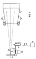
- FIG. 1 shows an X-ray diagnostic device for tomosynthesis, which has a radiation transmitter 1, to which a receiver 2 of a position detector is assigned in the exemplary embodiment.
- a radiation receiver 3 is assigned to the radiation transmitter 1 and receives the radiation coming from the radiation transmitter 1.
- a transmitter 4 of the position detector is assigned to this radiation receiver 3.
- the transmitter 4 is designed as an infrared transmitter, the light of which is converted by the receiver 2 into electrical signals. These electrical signals are fed to an evaluation device 11 (FIG. 2), which uses this to determine the distance, the angle of incidence and the direction of incidence.
- the voltage of a voltage source 5 is supplied to the transmitter 4.
- both the radiation receiver 3 and the transmitter 4 are arranged on a holder 6 designed as a bite holder.
- the position detector can be designed as a magnetic, electromagnetic, optical, acoustic or mechanical device.
- a transmitter 4 of the position detector on the radiation transmitter 1 and a receiver 2 of the position detector can be assigned to the radiation receiver 3.
- the transmitter 4 is provided on the radiation transmitter 1, for example, and transmits a beam which is reflected by a reference point assigned to the radiation receiver 3 and is received by a receiver 2 provided on the radiation transmitter 1.
- the position detector not only has a fixed assignment to the radiation transmitter 3, as shown in FIG. 1, but it can also be assigned directly and directly to the examination object.
- 3 shows that the examination object 7, for example the jaw, is assigned the magnets 8, the magnetic fields of which are received by magnetic field sensors 9 at the radiation receiver 3 and / or at the radiation transmitter 1 and converted into electrical signals which are then sent to the evaluation device 11 be fed.
- An electromagnetic device can also be used as a position detector, in which either the magnetic fields of coils are generated or can also be detected by means of coils. Using changing magnetic fields, the measurement of static interference fields can be decoupled and the accuracy of the measurement can be improved.
- the transmitter or receiver of the position detector can also be arranged on the examination object 7, for example on the head, in particular on the forehead (FIG. 4), or on a holding device 10 on the chin.
- the position detector By arranging the position detector at the greatest possible distance from the examination object 7, the measuring accuracy can be increased considerably because when the examination object 7 is moved out of the rest position, a larger lever, i.e. a larger deflection is effective.
- An X-ray diagnostic device has, as can be seen from FIG. 2, in addition to the radiation transmitter 1, the Position detector 2,4 and the radiation receiver 3 also a control computer 11 and an image reconstruction computer 12.
- the control computer 11 controls a voltage supply device 13 for the radiation transmitter 1, the transmitter 4 of the position detector, a signal control device 14 for the radiation receiver 3 and has a connection to the image reconstruction computer 12 to a memory 15 and to a display 16 and receives signals from the receiver 2 of the position detector.
- a further memory 17, control elements 18, an output unit 19 and an analog / digital converter are assigned to the image reconstruction computer 12 and convert the signals coming from the radiation receiver 3.
- the control computer 11 calculates the distance from the beam transmitter 1 to the beam receiver 3, the angle of incidence and the direction of incidence from the signals of the position detector. If the alignment of the radiation transmitter 1, examination object 7 and radiation receiver 3 deviates from a target assignment, the control computer 11 forms correction signals, which are supplied to the image reconstruction computer 12 either immediately or at a later point in time, after being temporarily stored in the memory 15, and at the calculation of a radiographic image of the examination subject 7 are taken into account. It is advantageous if, depending on the correction signals, the radiation transmitter 1 can be excited to emit radiation if predetermined limits of the correction signals are not exceeded.
- the display 16 can also be used to indicate that, for example, due to the movement of the examination object 7, it is not possible to take a blur-free image.
- the examination object 7 is usually fixed as rigidly as possible to the X-ray device using a bite holder, forehead support or ear olives, which is perceived as unpleasant.
- movement of the examination object 7 leads to a disturbance in the x-ray image generated, which is also undesirable is.
- correction signals are then formed from the signals of the position detector in order to assign the correct image contents to the object details from the desired, sharply to be depicted layer and to track the position of the desired layer of the patient movement before the tomographic blurring process is carried out.
- the correction signals generated from the position measurements then influence the derivation intervals for the individual images / individual image signals and their displacement parallel and perpendicular to the tomographic scanning direction and also include rotations of the individual images / individual image signals, changes in the magnification scale in the individual images / individual image signals and differentiated according to the direction and position of the slice image produced assembling effective individual images / individual image signals from a plurality of image strips / image signal strips according to derivation intervals which vary in the direction perpendicular to the tomographic scanning direction.
- FIG. 7 shows a coupling device 21 in principle, which limits or elastically couples the relative adjustment between the radiation transmitter 1 and the radiation receiver 3 or the examination object 7 or between the radiation receiver 3 and the examination object 7.
- This coupling device 21 has a first arm 22, which is connected to the radiation transmitter 1.
- the examination object (not shown in FIG. 7) is usually arranged in the area of the radiation receiver 3.
- the first and second arms 22, 23 are pivotally mounted about an axis of rotation 24.
- a position transducer 25 can be provided to detect the pivoting of the arms 22, 23.
- Rotation encoders or strain gauges are suitable as displacement transducers 25.
- the coupling device 21 is assigned two travel limiters 26, which limit the adjustability of the second arm 23 in the exemplary embodiment.
- a spring element 27 for example a leaf spring, which is connected to the arms 22, 23, then an elastic adjustment of the arms 22, 23 relative to one another and about the axis of rotation 24 is possible.
- the spring element 27 can advantageously be designed such that it produces a small restoring moment in the event of a small deviation from the shown assignment of the radiation transmitter 1 and the radiation receiver 3, and a large restoring moment in the case of a large deviation.
- the signals generated by the displacement sensor 25 are fed to the evaluation device 11.
- the arms 22, 23 can also be adjustable in other spatial directions about an axis perpendicular to the axis of rotation 24 or via a cardanic swivel joint.
Landscapes
- Health & Medical Sciences (AREA)
- Life Sciences & Earth Sciences (AREA)
- Medical Informatics (AREA)
- Engineering & Computer Science (AREA)
- Radiology & Medical Imaging (AREA)
- Molecular Biology (AREA)
- Biophysics (AREA)
- Nuclear Medicine, Radiotherapy & Molecular Imaging (AREA)
- Optics & Photonics (AREA)
- Pathology (AREA)
- Physics & Mathematics (AREA)
- Biomedical Technology (AREA)
- Heart & Thoracic Surgery (AREA)
- High Energy & Nuclear Physics (AREA)
- Surgery (AREA)
- Animal Behavior & Ethology (AREA)
- General Health & Medical Sciences (AREA)
- Public Health (AREA)
- Veterinary Medicine (AREA)
- Dentistry (AREA)
- Oral & Maxillofacial Surgery (AREA)
- Apparatus For Radiation Diagnosis (AREA)
Applications Claiming Priority (2)
| Application Number | Priority Date | Filing Date | Title |
|---|---|---|---|
| DE19619925A DE19619925C2 (de) | 1996-05-17 | 1996-05-17 | Röntgendiagnostikgerät für Tomosynthese |
| DE19619925 | 1996-05-17 |
Publications (2)
| Publication Number | Publication Date |
|---|---|
| EP0807404A1 true EP0807404A1 (fr) | 1997-11-19 |
| EP0807404B1 EP0807404B1 (fr) | 2003-03-26 |
Family
ID=7794577
Family Applications (1)
| Application Number | Title | Priority Date | Filing Date |
|---|---|---|---|
| EP97107307A Expired - Lifetime EP0807404B1 (fr) | 1996-05-17 | 1997-05-02 | Appareil de radiodiagnostique tomosynthétique |
Country Status (4)
| Country | Link |
|---|---|
| US (1) | US5828722A (fr) |
| EP (1) | EP0807404B1 (fr) |
| JP (1) | JPH1043179A (fr) |
| DE (2) | DE19619925C2 (fr) |
Cited By (1)
| Publication number | Priority date | Publication date | Assignee | Title |
|---|---|---|---|---|
| EP0904733A1 (fr) * | 1997-09-27 | 1999-03-31 | Kantonsspital Basel | Procédé et appareil pour l'enregistrement d'une image tridimensionnelle d'une partie du corps |
Families Citing this family (92)
| Publication number | Priority date | Publication date | Assignee | Title |
|---|---|---|---|---|
| US6289235B1 (en) * | 1998-03-05 | 2001-09-11 | Wake Forest University | Method and system for creating three-dimensional images using tomosynthetic computed tomography |
| US6081577A (en) * | 1998-07-24 | 2000-06-27 | Wake Forest University | Method and system for creating task-dependent three-dimensional images |
| US6540399B1 (en) | 1999-02-26 | 2003-04-01 | Dentsply Research & Development Corp. | Bite block for dental X-Ray procedures |
| DE19912854A1 (de) * | 1999-03-22 | 2000-10-05 | Sirona Dental Systems Gmbh | Verfahren zur Korrektur des Vergrößerungsfaktors bei digitalen Röntgenaufnahmen |
| JP2003511175A (ja) * | 1999-10-14 | 2003-03-25 | ツェーデーイー−ツェントルム・フューア・デンターレ・インノヴァティオネン・ゲゼルシャフト・ミット・ベシュレンクテル・ハフツング | 断層撮影法およびそのための装置 |
| US6381301B1 (en) * | 1999-12-01 | 2002-04-30 | Ronald E. Massie | Dental and orthopedic densitometry modeling system and method |
| US8126112B2 (en) * | 1999-12-01 | 2012-02-28 | Massie Ronald E | Osseo classification system and method |
| US8073101B2 (en) * | 1999-12-01 | 2011-12-06 | Massie Ronald E | Digital modality modeling for medical and dental applications |
| US6944262B2 (en) * | 1999-12-01 | 2005-09-13 | Massie Ronald E | Dental and orthopedic densitometry modeling system and method |
| US6671349B1 (en) | 2000-11-13 | 2003-12-30 | Olganix Corporation | Tomosynthesis system and registration method |
| JP3785576B2 (ja) * | 2002-04-24 | 2006-06-14 | 株式会社モリタ製作所 | 被写体ブレ補正手段、これを用いた医療用x線撮影装置 |
| DE10250005B4 (de) * | 2002-10-25 | 2009-03-19 | Sirona Dental Systems Gmbh | Aufbissvorrichtung zur Verwendung mit einem Panorama-Röntgengerät |
| US7123684B2 (en) | 2002-11-27 | 2006-10-17 | Hologic, Inc. | Full field mammography with tissue exposure control, tomosynthesis, and dynamic field of view processing |
| US7577282B2 (en) | 2002-11-27 | 2009-08-18 | Hologic, Inc. | Image handling and display in X-ray mammography and tomosynthesis |
| US10638994B2 (en) | 2002-11-27 | 2020-05-05 | Hologic, Inc. | X-ray mammography with tomosynthesis |
| US8565372B2 (en) | 2003-11-26 | 2013-10-22 | Hologic, Inc | System and method for low dose tomosynthesis |
| US7616801B2 (en) | 2002-11-27 | 2009-11-10 | Hologic, Inc. | Image handling and display in x-ray mammography and tomosynthesis |
| US8571289B2 (en) | 2002-11-27 | 2013-10-29 | Hologic, Inc. | System and method for generating a 2D image from a tomosynthesis data set |
| US7433507B2 (en) * | 2003-07-03 | 2008-10-07 | Ge Medical Systems Global Technology Co. | Imaging chain for digital tomosynthesis on a flat panel detector |
| FI118356B (fi) * | 2004-07-22 | 2007-10-15 | Planmeca Oy | Järjestely intraoraaliröntgenkuvantamisen yhteydessä |
| WO2006023674A1 (fr) * | 2004-08-16 | 2006-03-02 | Abr, Llc | Systeme d’alignement de transducteur rfid |
| US7662082B2 (en) | 2004-11-05 | 2010-02-16 | Theragenics Corporation | Expandable brachytherapy device |
| EP2602743B1 (fr) | 2004-11-15 | 2014-11-05 | Hologic, Inc. | Affichage et génération de géométrie de mise en correspondance de mammographies et d'images de tomosynthèse |
| EP3106094B1 (fr) | 2004-11-26 | 2021-09-08 | Hologic, Inc. | Systeme radiographique multimode integrant mammographie/tomosynthese |
| EP1886257A1 (fr) | 2005-05-11 | 2008-02-13 | Optosecurity Inc. | Procede et systeme d'inspection de bagages, de conteneurs de fret ou de personnes |
| US7991242B2 (en) | 2005-05-11 | 2011-08-02 | Optosecurity Inc. | Apparatus, method and system for screening receptacles and persons, having image distortion correction functionality |
| US10008184B2 (en) | 2005-11-10 | 2018-06-26 | Hologic, Inc. | System and method for generating a 2D image using mammography and/or tomosynthesis image data |
| US8079946B2 (en) | 2005-11-18 | 2011-12-20 | Senorx, Inc. | Asymmetrical irradiation of a body cavity |
| WO2007095330A2 (fr) | 2006-02-15 | 2007-08-23 | Hologic Inc | Biopsie mammaire et localisation a l'aiguille a l'aide de systemes de tomosynthese |
| US7899232B2 (en) | 2006-05-11 | 2011-03-01 | Optosecurity Inc. | Method and apparatus for providing threat image projection (TIP) in a luggage screening system, and luggage screening system implementing same |
| WO2007149402A2 (fr) * | 2006-06-16 | 2007-12-27 | Gendex Corporation | Système de positionnement d'appareil à rayons x intra-oral dentaire |
| US8494210B2 (en) | 2007-03-30 | 2013-07-23 | Optosecurity Inc. | User interface for use in security screening providing image enhancement capabilities and apparatus for implementing same |
| US20080032257A1 (en) * | 2006-08-01 | 2008-02-07 | Muckler Michael P | X-ray reference device and method of use |
| US7744279B2 (en) * | 2006-11-02 | 2010-06-29 | Carestream Health, Inc. | Orientation sensing apparatus for radiation imaging system |
| DE102007008962A1 (de) * | 2007-02-21 | 2008-08-28 | Sirona Dental Systems Gmbh | Dentale Kleinröntgeneinrichtung und Verfahren zur Positionierung eines Röntgenstrahlers |
| US7630533B2 (en) | 2007-09-20 | 2009-12-08 | Hologic, Inc. | Breast tomosynthesis with display of highlighted suspected calcifications |
| US20090086926A1 (en) * | 2007-09-27 | 2009-04-02 | Carestream Health, Inc. | Exposure centering apparatus for imaging system |
| US7792245B2 (en) | 2008-06-24 | 2010-09-07 | Hologic, Inc. | Breast tomosynthesis system with shifting face shield |
| US7991106B2 (en) | 2008-08-29 | 2011-08-02 | Hologic, Inc. | Multi-mode tomosynthesis/mammography gain calibration and image correction using gain map information from selected projection angles |
| KR100920848B1 (ko) * | 2008-11-17 | 2009-10-08 | 최영진 | 구강 내 방사선 촬영을 위한 각도 지시 필름 홀더 및 필름 지지부 |
| US9579524B2 (en) | 2009-02-11 | 2017-02-28 | Hologic, Inc. | Flexible multi-lumen brachytherapy device |
| US9248311B2 (en) | 2009-02-11 | 2016-02-02 | Hologic, Inc. | System and method for modifying a flexibility of a brachythereapy catheter |
| US10207126B2 (en) | 2009-05-11 | 2019-02-19 | Cytyc Corporation | Lumen visualization and identification system for multi-lumen balloon catheter |
| EP2485651B1 (fr) | 2009-10-08 | 2020-12-23 | Hologic, Inc. | Système de ponction-biopsie du sein |
| US9332951B2 (en) * | 2010-05-12 | 2016-05-10 | Trophy | Alignment apparatus for dental intraoral radiology |
| US9352172B2 (en) | 2010-09-30 | 2016-05-31 | Hologic, Inc. | Using a guide member to facilitate brachytherapy device swap |
| WO2015054518A1 (fr) | 2013-10-09 | 2015-04-16 | Hologic, Inc | Tomosynthèse du sein à rayons x améliorant la résolution spatiale y compris dans le sens de l'épaisseur du sein aplati |
| EP2624761B1 (fr) | 2010-10-05 | 2021-07-14 | Hologic, Inc. | Imagerie du sein par rayon x en position debout avec un mode de tomodensitométrie, de multiples modes de tomosynthèse et un mode de mammographie |
| US20120133600A1 (en) | 2010-11-26 | 2012-05-31 | Hologic, Inc. | User interface for medical image review workstation |
| US10342992B2 (en) | 2011-01-06 | 2019-07-09 | Hologic, Inc. | Orienting a brachytherapy applicator |
| CA2829349C (fr) | 2011-03-08 | 2021-02-09 | Hologic, Inc. | Systeme et procede pour une imagerie de seins a double energie et/ou a injection d'un agent de contraste pour un depistage, un diagnostic et une biopsie |
| US8670521B2 (en) * | 2011-06-02 | 2014-03-11 | Carestream Health, Inc. | Method for generating an intraoral volume image |
| US9111331B2 (en) | 2011-09-07 | 2015-08-18 | Rapiscan Systems, Inc. | X-ray inspection system that integrates manifest data with imaging/detection processing |
| JP2014534042A (ja) | 2011-11-27 | 2014-12-18 | ホロジック, インコーポレイテッドHologic, Inc. | マンモグラフィーおよび/またはトモシンセシス画像データを使用して2d画像を生成するためのシステムおよび方法 |
| US9805507B2 (en) | 2012-02-13 | 2017-10-31 | Hologic, Inc | System and method for navigating a tomosynthesis stack using synthesized image data |
| JP6388347B2 (ja) | 2013-03-15 | 2018-09-12 | ホロジック, インコーポレイテッドHologic, Inc. | 腹臥位におけるトモシンセシス誘導生検 |
| EP2967473B1 (fr) | 2013-03-15 | 2020-02-19 | Hologic, Inc. | Système et procédé pour explorer une pile de tomosynthèse comprenant une mise au point automatique |
| CA2924060A1 (fr) * | 2013-08-29 | 2015-03-05 | University Of Washington Through Its Center For Commercialization | Procedes et systemes de simulation d'une image radiographique dentaire |
| EP4278977A3 (fr) | 2013-10-24 | 2024-02-21 | Hologic, Inc. | Système et procédé de navigation pour une biopise du sein guidée par rayons x |
| JP6220253B2 (ja) * | 2013-12-13 | 2017-10-25 | 株式会社吉田製作所 | 歯科用x線撮影システム |
| JP6506769B2 (ja) | 2014-02-28 | 2019-04-24 | ホロジック, インコーポレイテッドHologic, Inc. | トモシンセシス画像スラブを生成し表示するためのシステムおよび方法 |
| US9724055B2 (en) * | 2014-03-07 | 2017-08-08 | Elwha Llc | Systems, devices, and methods for lowering dental x-ray dosage including feedback sensors |
| US9782136B2 (en) | 2014-06-17 | 2017-10-10 | The University Of North Carolina At Chapel Hill | Intraoral tomosynthesis systems, methods, and computer readable media for dental imaging |
| US10980494B2 (en) | 2014-10-20 | 2021-04-20 | The University Of North Carolina At Chapel Hill | Systems and related methods for stationary digital chest tomosynthesis (s-DCT) imaging |
| US10835199B2 (en) | 2016-02-01 | 2020-11-17 | The University Of North Carolina At Chapel Hill | Optical geometry calibration devices, systems, and related methods for three dimensional x-ray imaging |
| PL3764281T3 (pl) | 2016-02-22 | 2025-02-10 | Rapiscan Systems, Inc. | Sposoby identyfikacji broni palnej na obrazach radiograficznych |
| US11076820B2 (en) | 2016-04-22 | 2021-08-03 | Hologic, Inc. | Tomosynthesis with shifting focal spot x-ray system using an addressable array |
| US10631799B2 (en) * | 2016-12-07 | 2020-04-28 | Harris Corporation | Dental image collection device providing optical alignment features and related system and methods |
| CN110621233B (zh) | 2017-03-30 | 2023-12-12 | 豪洛捷公司 | 用于处理乳房组织图像数据的方法 |
| CN110662489B (zh) | 2017-03-30 | 2024-08-02 | 豪洛捷公司 | 用于靶向对象增强以生成合成乳房组织图像的系统和方法 |
| EP3600047A1 (fr) | 2017-03-30 | 2020-02-05 | Hologic, Inc. | Système et procédé de synthèse et de représentation d'image de caractéristique multiniveau hiérarchique |
| WO2018236565A1 (fr) | 2017-06-20 | 2018-12-27 | Hologic, Inc. | Procédé et système d'imagerie médicale à auto-apprentissage dynamique |
| DE202018006903U1 (de) | 2017-08-16 | 2024-07-29 | Hologic Inc. | Techniken zur Patientenbewegungsartefaktkompensation bei Brustbildgebung |
| EP3449835B1 (fr) | 2017-08-22 | 2023-01-11 | Hologic, Inc. | Système et méthode de tomographie assistée par ordinateur pour imager de multiples cibles anatomiques |
| WO2019040056A1 (fr) | 2017-08-23 | 2019-02-28 | Carestream Dental Technology Topco Limited | Système de tomosynthèse du côté d'un fauteuil dentaire |
| US10307233B1 (en) * | 2018-01-09 | 2019-06-04 | Albert Davydov | Method for utilizing a mandibular c-clamp to identify a fixed point of reference on a human jaw |
| US11090017B2 (en) | 2018-09-13 | 2021-08-17 | Hologic, Inc. | Generating synthesized projection images for 3D breast tomosynthesis or multi-mode x-ray breast imaging |
| WO2020068851A1 (fr) | 2018-09-24 | 2020-04-02 | Hologic, Inc. | Cartographie mammaire et localisation d'anomalie |
| CN112770674B (zh) | 2018-09-28 | 2024-08-06 | 豪洛捷公司 | 通过高密度元素抑制来合成乳腺组织的图像生成的系统和方法 |
| DE202019006040U1 (de) | 2018-11-25 | 2024-08-06 | Hologic Inc. | Multimodalitätsaufhängungsprotokolle |
| KR20210148132A (ko) | 2019-03-29 | 2021-12-07 | 홀로직, 인크. | 스닙-트리거링된 디지털 영상 보고서 생성 |
| EP3832689A3 (fr) | 2019-12-05 | 2021-08-11 | Hologic, Inc. | Systèmes et procédés pour améliorer la durée de vie d'un tube à rayons x |
| US12505645B2 (en) | 2020-03-27 | 2025-12-23 | Hologic, Inc. | Systems and methods for correlating regions of interest in multiple imaging modalities |
| JP7671776B2 (ja) | 2020-03-27 | 2025-05-02 | ホロジック, インコーポレイテッド | 複数の画像化モダリティにおける関心対象領域を識別するシステム及び方法 |
| US11471118B2 (en) | 2020-03-27 | 2022-10-18 | Hologic, Inc. | System and method for tracking x-ray tube focal spot position |
| US20220164951A1 (en) | 2020-11-20 | 2022-05-26 | Hologic, Inc. | Systems and methods for using ai to identify regions of interest in medical images |
| US11786191B2 (en) | 2021-05-17 | 2023-10-17 | Hologic, Inc. | Contrast-enhanced tomosynthesis with a copper filter |
| US12186119B2 (en) | 2021-10-05 | 2025-01-07 | Hologic, Inc. | Interactive model interface for image selection in medical imaging systems |
| US12254586B2 (en) | 2021-10-25 | 2025-03-18 | Hologic, Inc. | Auto-focus tool for multimodality image review |
| CN118318247A (zh) | 2021-11-29 | 2024-07-09 | 豪洛捷公司 | 用于将感兴趣的对象相关的系统和方法 |
| US12414217B2 (en) | 2022-02-07 | 2025-09-09 | Hologic, Inc. | Systems and methods for adaptively controlling filament current in an X-ray tube |
| DE102022206622B4 (de) * | 2022-06-29 | 2023-08-31 | Siemens Healthcare Gmbh | Vorrichtung zur Aufnahme einer Strahlengangskomponente für eine Röntgenstrahlung und Verfahren zum Bereitstellen einer Positionsinformation |
Citations (2)
| Publication number | Priority date | Publication date | Assignee | Title |
|---|---|---|---|---|
| US4211927A (en) * | 1978-11-24 | 1980-07-08 | Cgr Medical Corporation | Computerized tomography system |
| US4907251A (en) * | 1987-03-13 | 1990-03-06 | Kabushiki Kaisha Morita Seisakusho | Patient positioning device in medical panorama X-ray photographing apparatus |
Family Cites Families (5)
| Publication number | Priority date | Publication date | Assignee | Title |
|---|---|---|---|---|
| US5113424A (en) * | 1991-02-04 | 1992-05-12 | University Of Medicine & Dentistry Of New Jersey | Apparatus for taking radiographs used in performing dental subtraction radiography with a sensorized dental mouthpiece and a robotic system |
| US5359637A (en) * | 1992-04-28 | 1994-10-25 | Wake Forest University | Self-calibrated tomosynthetic, radiographic-imaging system, method, and device |
| US5629972A (en) * | 1993-05-18 | 1997-05-13 | Research Foundation Of State University Of New York | Intraoral radiograph alignment device |
| DE4414689C2 (de) * | 1994-04-26 | 1996-08-29 | Siemens Ag | Röntgendiagnostikeinrichtung |
| US5463669A (en) * | 1994-09-08 | 1995-10-31 | Kaplan; Jerome I. | Dental X-ray alignment system |
-
1996
- 1996-05-17 DE DE19619925A patent/DE19619925C2/de not_active Expired - Fee Related
-
1997
- 1997-05-02 EP EP97107307A patent/EP0807404B1/fr not_active Expired - Lifetime
- 1997-05-02 DE DE59709594T patent/DE59709594D1/de not_active Expired - Fee Related
- 1997-05-14 US US08/856,147 patent/US5828722A/en not_active Expired - Fee Related
- 1997-05-15 JP JP9125126A patent/JPH1043179A/ja active Pending
Patent Citations (2)
| Publication number | Priority date | Publication date | Assignee | Title |
|---|---|---|---|---|
| US4211927A (en) * | 1978-11-24 | 1980-07-08 | Cgr Medical Corporation | Computerized tomography system |
| US4907251A (en) * | 1987-03-13 | 1990-03-06 | Kabushiki Kaisha Morita Seisakusho | Patient positioning device in medical panorama X-ray photographing apparatus |
Cited By (2)
| Publication number | Priority date | Publication date | Assignee | Title |
|---|---|---|---|---|
| EP0904733A1 (fr) * | 1997-09-27 | 1999-03-31 | Kantonsspital Basel | Procédé et appareil pour l'enregistrement d'une image tridimensionnelle d'une partie du corps |
| US6259942B1 (en) | 1997-09-27 | 2001-07-10 | Surgical Navigation Specialist Inc. | Method and apparatus for recording a three-dimensional image of a body part |
Also Published As
| Publication number | Publication date |
|---|---|
| US5828722A (en) | 1998-10-27 |
| EP0807404B1 (fr) | 2003-03-26 |
| JPH1043179A (ja) | 1998-02-17 |
| DE19619925A1 (de) | 1997-11-20 |
| DE59709594D1 (de) | 2003-04-30 |
| DE19619925C2 (de) | 1999-09-09 |
Similar Documents
| Publication | Publication Date | Title |
|---|---|---|
| EP0807404B1 (fr) | Appareil de radiodiagnostique tomosynthétique | |
| DE19950793B4 (de) | Röntgeneinrichtung und Verfahren zur Bestimmung von Abbildungsparametern | |
| DE69738156T2 (de) | Verfahren und Gerät zur Aufnahme eines drei-dimensionalen Bildes eines Körperteils | |
| DE3808009C2 (de) | Vorrichtung zum positionieren des patienten bei einer medizinischen panorama-roentgenaufnahmeeinrichtung | |
| DE69418796T2 (de) | Medizinische Inspektionsvorrichtung und Verfahren zur Lokalisierung der Lage des Patiententisches | |
| DE19746093C2 (de) | C-Bogen-Röntgengerät | |
| EP1380263B1 (fr) | Procédé et dispositif pour la mesure de la position instantanée d'une structure d'un objet à examiner | |
| DE4414689A1 (de) | Röntgendiagnostikeinrichtung | |
| DE3853287T3 (de) | RöNTGENSTRAHLEN-TOMOGRAPHIEGERÄT MIT EINEM ORTUNGSDETEKTOR. | |
| EP0910989A1 (fr) | Appareil radiographique | |
| DE10341541B4 (de) | Vorrichtung zur Erkennung der Relativ-Position eines Röntgenstrahlers und eines Bildempfängers | |
| DE112006003039T5 (de) | Verfahren und Anordnung zur Röntgenbildgebung | |
| DE102007019827A1 (de) | System und Verfahren zur Ermittlung der Position eines Instruments | |
| WO2006024622A1 (fr) | Dispositif a rayons x | |
| EP1852822A2 (fr) | Génération d'image médicale tridimensionnelle avec positionnement indépendant de source d'émission et de détecteur | |
| DE102005034518A1 (de) | Computertomografie-Dosisindexierungs-Phantomauswahl zur Dosisdokumentierung | |
| DE102013200329B4 (de) | Verfahren und Vorrichtung zur Dejustagekorrektur für Bildgebungsverfahren | |
| EP1605828B1 (fr) | Appareil de radiographie | |
| DE3521293A1 (de) | Verfahren zur korrektur der raeumlichen messwerte einer drehbaren (gamma)-kamera | |
| DE102004052911B4 (de) | Röntgenstrahler mit einem Strahlergehäuse, Röntgeneinrichtung mit einem derartigen Röntgenstrahler und Computertomographiegerät mit einer derartigen Röntgeneinrichtung | |
| DE1956377B2 (de) | Geraet zum aufnehmen und aufzeichnen der raeumlichen verteilung radioaktiver strahlungsquellen in einem untersuchungsobjekt mittels einer szintillationskamera | |
| WO2011076416A1 (fr) | Procédé et système de production d'images radiographiques sans distorsion pour le diagnostic en odontologie ou en orthodontie | |
| EP3412207B1 (fr) | Imagerie mammaire | |
| EP1003420B1 (fr) | Appareil de diagnostic aux rayons x destine a la tomosynthese | |
| DE2646521A1 (de) | Verfahren zum eichen eines axial arbeitenden tomografischen abtastgeraets |
Legal Events
| Date | Code | Title | Description |
|---|---|---|---|
| PUAI | Public reference made under article 153(3) epc to a published international application that has entered the european phase |
Free format text: ORIGINAL CODE: 0009012 |
|
| AK | Designated contracting states |
Kind code of ref document: A1 Designated state(s): DE FI FR IT SE |
|
| RAP1 | Party data changed (applicant data changed or rights of an application transferred) |
Owner name: SIRONA DENTAL SYSTEMS GMBH & CO.KG |
|
| 17P | Request for examination filed |
Effective date: 19980519 |
|
| RAP1 | Party data changed (applicant data changed or rights of an application transferred) |
Owner name: SIRONA DENTAL SYSTEMS GMBH |
|
| GRAH | Despatch of communication of intention to grant a patent |
Free format text: ORIGINAL CODE: EPIDOS IGRA |
|
| GRAH | Despatch of communication of intention to grant a patent |
Free format text: ORIGINAL CODE: EPIDOS IGRA |
|
| GRAA | (expected) grant |
Free format text: ORIGINAL CODE: 0009210 |
|
| AK | Designated contracting states |
Designated state(s): DE FI FR IT SE |
|
| PG25 | Lapsed in a contracting state [announced via postgrant information from national office to epo] |
Ref country code: IT Free format text: LAPSE BECAUSE OF FAILURE TO SUBMIT A TRANSLATION OF THE DESCRIPTION OR TO PAY THE FEE WITHIN THE PRESCRIBED TIME-LIMIT;WARNING: LAPSES OF ITALIAN PATENTS WITH EFFECTIVE DATE BEFORE 2007 MAY HAVE OCCURRED AT ANY TIME BEFORE 2007. THE CORRECT EFFECTIVE DATE MAY BE DIFFERENT FROM THE ONE RECORDED. Effective date: 20030326 Ref country code: FR Free format text: LAPSE BECAUSE OF FAILURE TO SUBMIT A TRANSLATION OF THE DESCRIPTION OR TO PAY THE FEE WITHIN THE PRESCRIBED TIME-LIMIT Effective date: 20030326 Ref country code: FI Free format text: LAPSE BECAUSE OF FAILURE TO SUBMIT A TRANSLATION OF THE DESCRIPTION OR TO PAY THE FEE WITHIN THE PRESCRIBED TIME-LIMIT Effective date: 20030326 |
|
| REF | Corresponds to: |
Ref document number: 59709594 Country of ref document: DE Date of ref document: 20030430 Kind code of ref document: P |
|
| PG25 | Lapsed in a contracting state [announced via postgrant information from national office to epo] |
Ref country code: SE Free format text: LAPSE BECAUSE OF FAILURE TO SUBMIT A TRANSLATION OF THE DESCRIPTION OR TO PAY THE FEE WITHIN THE PRESCRIBED TIME-LIMIT Effective date: 20030626 |
|
| PG25 | Lapsed in a contracting state [announced via postgrant information from national office to epo] |
Ref country code: DE Free format text: LAPSE BECAUSE OF NON-PAYMENT OF DUE FEES Effective date: 20031202 |
|
| PLBE | No opposition filed within time limit |
Free format text: ORIGINAL CODE: 0009261 |
|
| STAA | Information on the status of an ep patent application or granted ep patent |
Free format text: STATUS: NO OPPOSITION FILED WITHIN TIME LIMIT |
|
| EN | Fr: translation not filed | ||
| 26N | No opposition filed |
Effective date: 20031230 |