EP0807487A2 - Device for transporting, clamping and laser beam welding of at least two sheet metal platines - Google Patents
Device for transporting, clamping and laser beam welding of at least two sheet metal platines Download PDFInfo
- Publication number
- EP0807487A2 EP0807487A2 EP96117819A EP96117819A EP0807487A2 EP 0807487 A2 EP0807487 A2 EP 0807487A2 EP 96117819 A EP96117819 A EP 96117819A EP 96117819 A EP96117819 A EP 96117819A EP 0807487 A2 EP0807487 A2 EP 0807487A2
- Authority
- EP
- European Patent Office
- Prior art keywords
- welding
- sheet metal
- metal plates
- tables
- welded
- Prior art date
- Legal status (The legal status is an assumption and is not a legal conclusion. Google has not performed a legal analysis and makes no representation as to the accuracy of the status listed.)
- Withdrawn
Links
Images

Classifications
-
- B—PERFORMING OPERATIONS; TRANSPORTING
- B23—MACHINE TOOLS; METAL-WORKING NOT OTHERWISE PROVIDED FOR
- B23K—SOLDERING OR UNSOLDERING; WELDING; CLADDING OR PLATING BY SOLDERING OR WELDING; CUTTING BY APPLYING HEAT LOCALLY, e.g. FLAME CUTTING; WORKING BY LASER BEAM
- B23K26/00—Working by laser beam, e.g. welding, cutting or boring
- B23K26/02—Positioning or observing the workpiece, e.g. with respect to the point of impact; Aligning, aiming or focusing the laser beam
- B23K26/06—Shaping the laser beam, e.g. by masks or multi-focusing
- B23K26/067—Dividing the beam into multiple beams, e.g. multi-focusing
- B23K26/0673—Dividing the beam into multiple beams, e.g. multi-focusing into independently operating sub-beams, e.g. beam multiplexing to provide laser beams for several stations
-
- B—PERFORMING OPERATIONS; TRANSPORTING
- B23—MACHINE TOOLS; METAL-WORKING NOT OTHERWISE PROVIDED FOR
- B23K—SOLDERING OR UNSOLDERING; WELDING; CLADDING OR PLATING BY SOLDERING OR WELDING; CUTTING BY APPLYING HEAT LOCALLY, e.g. FLAME CUTTING; WORKING BY LASER BEAM
- B23K26/00—Working by laser beam, e.g. welding, cutting or boring
- B23K26/02—Positioning or observing the workpiece, e.g. with respect to the point of impact; Aligning, aiming or focusing the laser beam
- B23K26/06—Shaping the laser beam, e.g. by masks or multi-focusing
- B23K26/067—Dividing the beam into multiple beams, e.g. multi-focusing
-
- B—PERFORMING OPERATIONS; TRANSPORTING
- B23—MACHINE TOOLS; METAL-WORKING NOT OTHERWISE PROVIDED FOR
- B23K—SOLDERING OR UNSOLDERING; WELDING; CLADDING OR PLATING BY SOLDERING OR WELDING; CUTTING BY APPLYING HEAT LOCALLY, e.g. FLAME CUTTING; WORKING BY LASER BEAM
- B23K26/00—Working by laser beam, e.g. welding, cutting or boring
- B23K26/08—Devices involving relative movement between laser beam and workpiece
- B23K26/083—Devices involving movement of the workpiece in at least one axial direction
- B23K26/0838—Devices involving movement of the workpiece in at least one axial direction by using an endless conveyor belt
-
- B—PERFORMING OPERATIONS; TRANSPORTING
- B23—MACHINE TOOLS; METAL-WORKING NOT OTHERWISE PROVIDED FOR
- B23K—SOLDERING OR UNSOLDERING; WELDING; CLADDING OR PLATING BY SOLDERING OR WELDING; CUTTING BY APPLYING HEAT LOCALLY, e.g. FLAME CUTTING; WORKING BY LASER BEAM
- B23K26/00—Working by laser beam, e.g. welding, cutting or boring
- B23K26/20—Bonding
- B23K26/21—Bonding by welding
- B23K26/24—Seam welding
- B23K26/26—Seam welding of rectilinear seams
-
- B—PERFORMING OPERATIONS; TRANSPORTING
- B23—MACHINE TOOLS; METAL-WORKING NOT OTHERWISE PROVIDED FOR
- B23K—SOLDERING OR UNSOLDERING; WELDING; CLADDING OR PLATING BY SOLDERING OR WELDING; CUTTING BY APPLYING HEAT LOCALLY, e.g. FLAME CUTTING; WORKING BY LASER BEAM
- B23K2101/00—Articles made by soldering, welding or cutting
- B23K2101/18—Sheet panels
- B23K2101/185—Tailored blanks
Definitions
- the invention relates to a device for transporting, tensioning and laser beam welding of at least two sheet metal plates of the same or different thicknesses, the same or different sizes and shapes and the same or different materials to form a sheet metal plate.
- a device for welding at least two geometrically differently designed metal sheets is known. These metal sheets can be coated on one or both sides and have the same or different sheet thickness. They are used particularly in car body construction.
- a laser beam welding device is used for welding. Two conveyors arranged parallel to each other with a large number of clamping pallets are used. A sheet of metal from a separating magazine is fed into each clamping pallet and clamped there. The clamping pallets are passed through the conveying devices under a laser beam welding device after prior complex welding gap positioning, the weld seam being produced. The welded metal sheets are then transferred to a similar system for attaching another metal sheet or sent for further processing. The clamping pallets are then conveyed back to their starting point below the conveyor line described above and reloaded there.
- the design of the welding system should constantly maintain optimal welding conditions during the welding process.
- the device should also be economically usable for smaller lot sizes, although the basic design of the assemblies should be designed for the processing of large quantities.
- the solution according to claim 1 makes it possible to perform at least two weld seams for connecting three different sheet metal blanks with the two welding tables lying next to one another with little space and movement expenditure. Thanks to the versatility of the welding bars, they can be easily and quickly adapted to the different positions of the welding seams. The tension of the sheet metal plates from below against the welding bar, together with the welding optics that can be moved on the welding bar, result in optimal welding conditions and thus perfect weld seams.
- the gripper tongs move the welded sheet metal plates from welding table to welding table or to the storage table in a relatively simple manner.
- Claim 2 describes a common laser for both welding tables. This solution is made possible by the welding tables arranged directly next to each other and leads to high cost savings.
- Claims 3 to 7 and 9 show the wide range of applicability for the different numbers of sheet metal blanks and their shapes, the conversion of the system from one sheet metal blank shape to another is possible with little effort and thus very quickly.
- the device can be manually adjusted for cases of rare retrofitting. Numerical positioning drives can be used to advantage when frequent retrofitting is required.
- Fig. 1 two welding tables 1, 2 are arranged directly next to each other.
- Your table surface 3 consists of strip-shaped elements which are easily exchangeable in the side frame parts 4; 5; 6 of the welding tables 1; 2.
- the frame parts 4; 5; 6 of the welding tables 1; 2 are located on the sides of the welding tables 1; 2 lying transversely to the welding direction.
- the frame parts 4, 5, 6 are designed as a portal, on the horizontally extending supports of which guides 7 are provided which are parallel to the table surfaces 3.
- guides 7 On each of these guides 7, a carriage 8 is mounted so that it can be moved and locked.
- These slides 8 each carry one end of a welding bar 9 which extends across the welding table 1; 2 in the welding direction.
- the welding bar 9 consists of two L-shaped cheeks, the short legs of which point towards one another and form a narrow slot which is arranged above the welding joint.
- a guide is arranged on the top of each cheek, on which a carriage 10 is movably supported.
- the carriage 10 carries a welding optics, which cooperates via a beam guide 11 with a mirror of a switch 12 arranged next to the welding table 1.
- This switch 12 and the switch 12 of the other welding table 2 lie in the beam path of a laser device 13.
- Below the welding bar 10 the surface of a clamping device 14 acting against the underside of the welding bar 9 is arranged in the table surface 3.
- the clamping device 14 is displaceably and securely mounted in the same way as the welding bar 9.
- a guide 16 extending through the portals of both welding tables 1; 2 to the storage table 15 is fastened to the free side of the welding table 1; 2 parallel to the welding bar 9.
- gripper tongs 17 are attached in accordance with the number of sheet metal plates to be welded at the same time. They lie in the table plane and transport the welded sheet metal plates in cycles.
- Conical guide means (not shown) are adjustably arranged in the table surface 3 in accordance with the sheet metal shapes. Between them there is a thrust piston unit (not shown), the piston rod of which is directed towards the weld joint.
- the starting position of the piston rod is selected so that the sheet metal plate to be welded can be placed in front of it and then positioned by the stroke of the piston rod with its edge to be welded onto the weld joint.
- Such thrust piston units are arranged on both sides of the welding bar 9.
- two transport pallets 18 are mirrored on guide rails 19 which point away from the welding tables 1; 2.
- the individual sheet metal plates are stored in stacks in the arrangement between adjustable guide means, such as stanchions, which they then take up on the welding tables 1; 2 should.
- prefabricated pallets 20 are provided in the same arrangement.
- a storage table 15 for the welded sheet metal plates is arranged.
- a portal 21 covering the entire length is set up.
- Transport robots 22 are attached to this, one of which transports the individual blanks to the first and second welding tables 1; 2 by means of a suction spider 23, and the other also brings the finished welded sheet metal blanks to further processing or removal by means of a suction spider 23.
- the facility operates as follows: Outside the facility 18 stanchions are set on the transport pallets so that they hold the sheet metal plates in the later welding position. 1, three differently sized and thick sheet metal plates 24; 25; 26 are to be connected to one another. The size of the welding tables 1, 2 makes it possible to place five such metal plate columns next to one another.
- the transport pallet 18 is moved into the system and fixed there. Now the stack of boards is spread in a known manner and the upper layer of the sheet metal boards is gripped by the suction spider 23 pivoted over it. The transport robot 22 then pivots the suction spider 23 over the first welding table 1 and places the first 24 and second rows of sheet metal plates 25 there on both sides of the welding bar 9.
- the transport robot 22 then pivots further to the second welding table 2 and deposits the third row of sheet metal plates 26 there next to the welding bar 9.
- the transport robot 22 then pivots back to the transport pallet 18 and detects a further layer of sheet metal plates 24, 25, 26 there.
- the sheet metal plates 24 of the first row are positioned between the centering cones by the piston rods of the thrust piston units on the weld joint and there by the clamping device 14 against the welding bar 9 curious; excited.
- the sheet metal plates 25 of the second row are then pressed against the first row 24 by their pushing piston units and tensioned there. In this way, the sheet metal plates 24, 25 lie exactly in one plane with their surface facing the welding bar 9.
- the carriage 10 with the welding optics is moved along the weld joint and the weld seam is generated by the appropriately controlled laser beam.
- the gripper tongs 17 have gripped the sheet metal plates 24 facing them.
- the gripper tongs 17 are moved with the welded metal plates 24, 25 to the second welding table 2.
- the welded metal plates 24, 25 are positioned and tensioned in the same way under the weld joint.
- the third row of sheet metal blanks 26 is pressed against the tensioned sheet metal blanks 24, 25 by the push piston units there and welded tensioned in the manner described above.
- the gripper tongs 17 of the first welding table 1 have been moved back there and grip the welded first and second rows of sheet metal blanks in the following cycle.
- the gripper tongs 17 of the second welding table 2 grip the welded metal plates 24; 25; 26 of the first, second and third rows. These are moved by moving the gripper tongs 17 onto the storage table 15, while the gripper tongs 17 of the first welding table 1 move those of the welded metal plates of the first and second rows of the subsequent cycle under the weld joint of the second welding table 2.
- the movements of the feeding transport robot 22 are arranged according to the cycle in this transport sequence.
- the removal robot 22 removes the welded sheet-metal blanks 24; 25; 26 from the storage table 15 in the same rhythm and, on a case-by-case basis, either takes them for further processing or places them in stacks on the finished part pallets 20.
- 2 shows the welding of two large sheet metal plates 27, 28 with parallel edges and a weld seam. These two sheet metal plates 27, 28 are fetched from the transport pallet 18 with the suction spider 23 of the transport robot 22 and on both sides of the welding bar 9 on the first one Welding table 1 stored. There a sheet metal plate 27 is positioned under the weld joint and tensioned. Then the second sheet metal plate 28 is pressed against the clamped first sheet metal plate 27 and also clamped.
- the carriage 10 moves with the welding optics along the welding bar 9 and thereby generates the weld seam.
- the gripper tongs 17 have gripped the first sheet metal plate 27 and, after releasing the tension, transport the welded first and second sheet metal plates 27, 28 to the second welding table 2. Since only one weld seam is to be carried out, this welding table 2 serves as an intermediate storage.
- the welded sheet metal plate 27; 28 deposited there is moved to the storage table 15. 3 shows the production of weld seams on non-parallel edges of three sheet metal plates 29; 30; 31. This is done in the manner described above.
- the possibility of adjusting the welding bars 9 and the clamping devices 14 to an angle is used, which deviates from the rectangular position to the guides 7 on the welding table 1; 2, the angle of the non-parallel edges of the sheet metal plates 29; 30; 31 corresponds.
- the adjustment angle of the welding bar 9 of the first welding table 1 is opposite to that of the second welding table 2.
- the welding bars 9 can also be arranged at right angles to their guides 7 and the sheet metal plates 29; 30; 31 can be inserted at an angle such that the edges to be welded are positioned under the weld joint. It is necessary to fold the welded first and second sheet metal plates 29; 30 back so far before transporting them onto the second welding table 2 that their outer edges lie parallel to the welding bar 9.
Landscapes
- Physics & Mathematics (AREA)
- Optics & Photonics (AREA)
- Engineering & Computer Science (AREA)
- Plasma & Fusion (AREA)
- Mechanical Engineering (AREA)
- Laser Beam Processing (AREA)
- Automobile Manufacture Line, Endless Track Vehicle, Trailer (AREA)
Abstract
Description
Die Erfindung betrifft eine Einrichtung zum Transportieren, Spannen und Laserstrahlschweißen von mindestens zwei Blechplatinen gleicher oder unterschiedlicher Stärken, gleicher oder unterschiedlicher Größen und Formen und gleicher oder unterschiedlicher Werkstoffe zu einer Blechplatine.The invention relates to a device for transporting, tensioning and laser beam welding of at least two sheet metal plates of the same or different thicknesses, the same or different sizes and shapes and the same or different materials to form a sheet metal plate.
Es ist eine Einrichtung zum Verschweißen von mindestens zwei geometrisch unterschiedlich gestalteter Blechtafeln bekannt. Diese Blechtafeln können ein- oder doppelseitig beschichtet sein und gleiche oder unterschiedliche Blechdicke haben. Sie werden insbesondere im Kfz-Karosseriebau verwendet. Zum Schweißen kommt eine Laserstrahlschweißeinrichtung zum Einsatz. Es werden zwei parallel zueinander angeordnete Fördereinrichtungen mit einer großen Anzahl von Spannpaletten verwendet. In jede Spannpalette wird eine Blechtafel aus einem Vereinzelungsmagazin zugeführt und dort gespannt. Durch die Fördereinrichtungen werden die Spannpaletten unter einer Laserstrahlschweißeinrichtung nach vorheriger aufwendiger Schweißspaltpositionierung hindurchgeführt, wobei die Schweißnaht erzeugt wird. Danach werden die verschweißten Blechtafeln an eine gleichartige Anlage zur Anfügung einer weiteren Blechtafel übergeben oder der Weiterverarbeitung zugeführt. Die Spannpaletten werden dann unterhalb des vorstehend beschriebenen Förderstranges an ihre Ausgangsstelle zurückbefördert und dort neu beladen.
Um die jeweils die zusammenzuschweißenden Blechtafeln tragenden Spannpaletten beim Schweißvorgang genau zueinander zu positionieren, bedarf es an der Schweißanlage einer zusätzlichen zwangsläufigen Fördereinrichtung, die die zusammengehörigen Palettenpaare synchron durch die Schweißanlage bewegt. Diese Anlage erfordert durch die verwendeten Fördereinrichtungen einen hohen Platzbedarf. Da die Blechtafeln während des Schweißvorganges bewegt werden müssen, ist es nicht möglich, ständig optimale Schweißbedingungen zu gewährleisten. Dadurch entstehen teilweise unbefriedigende Schweißnähte, die für eine Weiterverarbeitung nicht geeignet sind. Durch die Art der Vereinzelung der Blechtafeln und die auf sie abgestimmten Spanneinrichtungen ist eine Umrüstung der Anlage auf andere Blechtafeln mit hohem Aufwand verbunden. Nichtparallele Schweißnähte sind auf dieser Anlage nicht herstellbar (EP 0 438 615 A1).A device for welding at least two geometrically differently designed metal sheets is known. These metal sheets can be coated on one or both sides and have the same or different sheet thickness. They are used particularly in car body construction. A laser beam welding device is used for welding. Two conveyors arranged parallel to each other with a large number of clamping pallets are used. A sheet of metal from a separating magazine is fed into each clamping pallet and clamped there. The clamping pallets are passed through the conveying devices under a laser beam welding device after prior complex welding gap positioning, the weld seam being produced. The welded metal sheets are then transferred to a similar system for attaching another metal sheet or sent for further processing. The clamping pallets are then conveyed back to their starting point below the conveyor line described above and reloaded there.
In order to position the clamping pallets carrying the metal sheets to be welded exactly to one another during the welding process, an additional inevitable conveyor device is required on the welding system, which moves the associated pallet pairs synchronously through the welding system. This system requires a lot of space due to the conveyor equipment used. Since the metal sheets during during the welding process, it is not possible to guarantee optimal welding conditions at all times. This results in unsatisfactory weld seams, which are not suitable for further processing. Due to the type of separation of the metal sheets and the tensioning devices that are matched to them, the system can be converted to other metal sheets with great effort. Non-parallel weld seams cannot be produced on this system (EP 0 438 615 A1).
Es ist Aufgabe der Erfindung, eine Einrichtung der oben genannten Gattung dahingehend zu verbessern, daß der Platzbedarf erheblich reduziert ist und daß die Einrichtung auch geeignet ist, Schweißnähte an nichtparallelen Verbindungskanten von Blechplatinen auszuführen. Weiterhin soll die Einrichtung auf Blechplatinen anderer Größe und/oder anderer Form mit wenig Aufwand umrüstbar sein. Die Ausbildung der Schweißanlage soll während des Schweißvorganges konstant optimale Schweißbedingungen einhalten. Die Einrichtung soll auch wirtschaftlich für kleinere Losgrößen verwendbar sein, obwohl die prinzipielle Gestaltung der Baugruppen auf die Bearbeitung großer Stückzahlen ausgelegt sein soll.It is an object of the invention to improve a device of the type mentioned above in such a way that the space requirement is considerably reduced and that the device is also suitable for performing weld seams on non-parallel connecting edges of sheet metal boards. Furthermore, the device should be able to be converted to metal plates of a different size and / or shape with little effort. The design of the welding system should constantly maintain optimal welding conditions during the welding process. The device should also be economically usable for smaller lot sizes, although the basic design of the assemblies should be designed for the processing of large quantities.
Die Aufgabe wird erfindungsgemäß durch die Merkmale des Patentanspruches 1 gelöst. Die Patentansprüche 2 bis 9 beinhalten vorteilhafte Ausgestaltungen der Merkmale des Patentanspruches 1.The object is achieved by the features of
Die Lösung nach Patentanspruch 1 ermöglicht es durch die nebeneinanderliegenden beiden Schweißtische mit wenig Platz- und Bewegungsaufwand mindestens zwei Schweißnähte zur Verbindung von drei verschiedenen Blechplatinen auszuführen. Durch die vielseitige Verstellbarkeit der Schweißbalken lassen sich diese an die unterschiedlichen Lagen der Schweißnähte auf einfache und schnelle Weise anpassen. Die Spannung der Blechplatinen von unten gegen den Schweißbalken ergibt zusammen mit der auf dem Schweißbalken verfahrbaren Schweißoptik optimale Schweißbedingungen und damit einwandfreie Schweißnähte.The solution according to
Die Greiferzangen bewegen in wenig aufwendiger Art die verschweißten Blechplatinen von Schweißtisch zu Schweißtisch bzw. zum Ablagetisch.
Patentanspruch 2 beschreibt einen gemeinsamen Laser für beide Schweißtische. Diese Lösung wird ermöglicht durch die unmittelbar nebeneinander angeordneten Schweißtische und führt zu hohen Kosteneinsparungen.
Die Patentansprüche 3 bis 7 und 9 zeigen die breit gefächerte Anwendbarkeit für die unterschiedlichen Stückzahlen von Blechplatinen sowie deren Formen, wobei die Umrüstung der Anlage von einer Blechplatinenform auf eine andere mit geringem Aufwand und somit sehr schnell möglich ist.
Nach Patentanspruch 8 kann die Einrichtung für Fälle von seltener Umrüstung manuell verstellt werden. Bei häufiger Umrüstung sind numerische Positionierantriebe vorteilhaft einsetzbar.The gripper tongs move the welded sheet metal plates from welding table to welding table or to the storage table in a relatively simple manner.
According to
In den Zeichnungen ist die Erfindung an mehreren Ausführungsbeispielen erläutert. Es zeigen
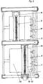
- Fig. 1
- eine Draufsicht auf die vollständige Einrichtung.
- Fig. 2
- eine Draufsicht auf beide Schweißtische mit zwei tischgroßen Platinen und einer Schweißnaht und
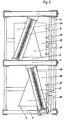
- Fig. 3
- eine Draufsicht auf beide Schweißtische mit schräggestellten Schweißbalken.
- Fig. 1
- a top view of the full setup.
- Fig. 2
- a plan view of both welding tables with two table-sized boards and a weld and
- Fig. 3
- a plan view of both welding tables with inclined welding bars.
In Fig. 1 sind unmittelbar nebeneinander zwei Schweißtische 1;2 angeordnet. Ihre Tischfläche 3 besteht aus leistenförmigen Elementen, die leicht wechselbar in den seitlichen Rahmenteilen 4;5;6 der Schweißtische 1;2 geführt sind. Die Rahmenteile 4;5;6 der Schweißtische 1;2 befinden sich an den quer zur Schweißrichtung liegenden Seiten der Schweißtische 1;2. Oberhalb der Tischflächen 3 sind die Rahmenteile 4;5;6 als Portal ausgebildet, auf deren horizontal verlaufenden Trägern parallel zu den Tischflächen 3 liegende Führungen 7 vorgesehen sind. Auf jeder dieser Führungen 7 ist ein Schlitten 8 verfahr- und feststellbar gelagert. Diese Schlitten 8 tragen jeder ein Ende eines Schweißbalkens 9, der sich in Schweißrichtung quer über den Schweißtisch 1;2 erstreckt. Der nicht gezeichnete Querschnitt durch den Schweißbalken 9 besteht aus zwei L-förmigen Wangen, deren kurze Schenkel zueinander zeigen und einen schmalen Schlitz bilden, der über der Schweißfuge angeordnet ist. Auf der Oberseite der Wangen ist je eine Führung angeordnet, auf der ein Schlitten 10 verfahrbar gelagert ist. Der Schlitten 10 trägt eine Schweißoptik, die über eine Strahlführung 11 mit einem Spiegel einer neben dem Schweißtisch 1 angeordneten Weiche 12 zusammenarbeitet. Diese Weiche 12 und die Weiche 12 des anderen Schweißtisches 2 liegt im Strahlengang eines Lasergerätes 13. Unterhalb des Schweißbalkens 10 ist in der Tischfläche 3 die Oberfläche einer gegen die Unterseite des Schweißbalkens 9 wirkenden Spanneinrichtung 14 angeordnet. Die Spanneinrichtung 14 ist in gleicher Weise verschieb- und feststellbar gelagert wie der Schweißbalken 9. Parallel zum Schweißbalken 9 ist an der freien Seite des Schweißtisches 1;2 eine durch die Portale beider Schweißtische 1;2 bis zum Ablagetisch 15 reichende Führung 16 befestigt. An den auf ihr für jeden Schweißtisch 1;2 gelagerten Schlitten sind entsprechend der Anzahl der gleichzeitig zu verschweißenden Blechplatinen Greiferzangen 17 angebracht, die in der Tischebene liegend, die geschweißten Blechplatinen taktweise transportieren. In der Tischfläche 3 sind entsprechend der Blechplatinen-Formen kegelförmige Führungsmittel (nicht gezeichnet) verstellbar angeordnet. Zwischen diesen befindet sich je eine Schubkolbeneinheit (nicht gezeichnet), deren Kolbenstange zur Schweißfuge gerichtet ist. Die Ausgangsstellung der Kolbenstange ist so gewählt, daß vor ihr die zu schweißende Blechplatine abgelegt werden kann und dann durch den Hub der Kolbenstange mit ihrer zu verschweißenden Kante auf die Schweißfuge positioniert wird. Derartige Schubkolbeneinheiten sind beidseitig des Schweißbalkens 9 angeordnet.
Spiegelbildlich sind neben den beiden Schweißtischen 1;2 zwei Transportpaletten 18 auf von den Schweißtischen 1;2 wegweisenden Führungsschienen 19 gelagert. Auf den Transportpaletten 18 sind zwischen verstellbaren Führungsmitteln, wie Rungen, die einzelnen Blechplatinen stapelweise in der Anordnung gelagert, die sie dann auf den Schweißtischen 1;2 einnehmen sollen. Neben den Transportpaletten 18 sind in gleicher Anordnung Fertigteilpaletten 20 vorgesehen.
Neben den beiden Schweißtischen 1;2 (in Schweißrichtung gesehen) ist ein Ablagetisch 15 für die fertiggeschweißten Blechplatinen angeordnet.
Zwischen den Transportpaletten 18 und den Fertigteilpaletten 20 einerseits und den Schweißtischen 1;2 und dem Ablagetisch 15 andererseits ist ein die gesamte Länge überdeckendes Portal 21 aufgestellt. An diesem sind Transportroboter 22 angebracht, von denen einer die einzelnen Platinen mittels einer Saugerspinne 23 zum ersten und zweiten Schweißtisch 1;2 transportiert und der andere die fertiggeschweißten Blechplatinen ebenfalls mittels einer Saugerspinne 23 zur Weiterverarbeitung oder zum Abtransport bringt.In Fig. 1, two welding tables 1, 2 are arranged directly next to each other. Your
In addition to the two welding tables 1; 2, two
In addition to the two welding tables 1; 2 (viewed in the welding direction), a storage table 15 for the welded sheet metal plates is arranged.
Between the
Die Arbeitsweise der Einrichtung ist folgende:
Außerhalb der Einrichtung werden auf den Transportpaletten 18 Rungen so eingestellt, daß sie die Blechplatinen in der späteren Schweißposition halten. In der Fig. 1 sind drei verschieden große und dicke Blechplatinen 24;25;26 miteinander zu verbinden. Die Größe der Schweißtische 1;2 erlaubt es, fünf derartiger Blechplatinenspalten nebeneinander aufzulegen. Die Transportpalette 18 wird in die Anlage eingefahren und dort festgestellt. Nun werden die Platinenstapel in bekannter Weise gespreizt und die obere Lage der Blechplatinen durch die darübergeschwenkte Saugerspinne 23 erfaßt. Der Transportroboter 22 schwenkt dann die Saugerspinne 23 über den ersten Schweißtisch 1 und legt dort die erste 24 und zweite Reihe Blechplatinen 25 beidseitig des Schweißbalkens 9 ab. Anschließend schwenkt der Transportroboter 22 weiter zum zweiten Schweißtisch 2 und legt dort die dritte Reihe der Blechplatinen 26 neben dem Schweißbalken 9 ab. Danach schwenkt der Transportroboter 22 zurück zur Transportpalette 18 und erfaßt dort eine weitere Lage Blechplatinen 24;25;26. Zwischenzeitlich werden die Blechplatinen 24 der ersten Reihe zwischen den Zentrierkegeln durch die Kolbenstangen der Schubkolbeneinheiten auf die Schweißfuge positioniert und dort durch die Spanneinrichtung 14 gegen den Schweißbalken 9 gespannt. Anschließend werden die Blechplatinen 25 der zweiten Reihe durch deren Schubkolbeneinheiten gegen die erste Reihe 24 gedrückt und dort gespannt. Auf diese Weise liegen die Blechplatinen 24;25 mit ihrer zum Schweißbalken 9 zeigenden Oberfläche genau in einer Ebene. Nun wird der Schlitten 10 mit der Schweißoptik entlang der Schweißfuge verfahren und durch den entsprechend gesteuerten Laserstrahl die Schweißnaht erzeugt. Zwischenzeitlich haben die Greiferzangen 17 die ihnen zugewandten Blechplatinen 24 ergriffen. Nach Lösen der Spanneinrichtung 14 werden die Greiferzangen 17 mit den verschweißten Blechplatinen 24;25 zum zweiten Schweißtisch 2 verfahren. Dort werden die verschweißten Blechplatinen 24;25 in gleicher Weise unter die Schweißfuge positioniert und gespannt. Nun wird die dritte Reihe Blechplatinen 26 durch die dortigen Schubkolbeneinheiten gegen die gespannten Blechplatinen 24;25 gedrückt und gespannt in der vorstehend beschriebenen Art verschweißt. Zwischenzeitlich sind die Greiferzangen 17 des ersten Schweißtisches 1 nach dort zurückgefahren worden und ergreifen die verschweißten ersten und zweiten Reihen Blechplatinen des Folgetaktes. Die Greiferzangen 17 des zweiten Schweißtisches 2 ergreifen die verschweißten Blechplatinen 24;25;26 der ersten, zweiten und dritten Reihe. Diese werden durch Verschieben der Greiferzangen 17 auf den Ablagetisch 15 bewegt, während die Greiferzangen 17 des ersten Schweißtisches 1 die der verschweißten Blechplatinen der ersten und zweiten Reihe des Foltgetaktes unter die Schweißfuge des zweiten Schweißtisches 2 bewegen. In diesen Transportablauf sind die Bewegungen des zuführenden Transportroboters 22 taktgemäß eingeordnet. Der abführende Transportroboter 22 entnimmt im gleichen Rhythmus die fertiggeschweißten Blechplatinen 24;25;26 vom Ablagetisch 15 und bringt sie von Fall zu Fall entweder zur Weiterverarbeitung oder legt sie stapelweise auf den Fertigteilpaletten 20 ab. In Fig. 2 ist das Verschweißen zweier großer Blechplatinen 27;28 mit parallelen Kanten und einer Schweißnaht gezeigt. Diese beiden Blechplatinen 27;28 werden mit der Saugerspinne 23 des Transportroboters 22 von der Transportpalette 18 geholt und beidseitig des Schweißbalkens 9 auf dem ersten Schweißtisch 1 abgelegt. Dort wird eine Blechplatine 27 unter die Schweißfuge positioniert und gespannt. Anschließend wird die zweite Blechplatine 28 gegen die festgespannte erste Blechplatine 27 gedrückt und ebenfalls gespannt. Nun verfährt der Schlitten 10 mit der Schweißoptik entlang des Schweißbalkens 9 und erzeugt dabei die Schweißnaht. Währenddessen haben die Greiferzangen 17 die erste Blechplatine 27 erfaßt und transportieren nach Lösen der Spannung die verschweißte erste und zweite Blechplatine 27;28 auf den zweiten Schweißtisch 2. Da nur eine Schweißnaht auszuführen ist, dient dieser Schweißtisch 2 als Zwischenlager. Beim nächsten Takt wird die dort abgelegte verschweißte Blechplatine 27;28 zum Ablagetisch 15 bewegt.
Fig. 3 zeigt die Herstellung von Schweißnähten an nichtparallelen Kanten dreier Blechplatinen 29;30;31. Dieses erfolgt ablaufmäßig in der vorbeschriebenen Art. Es wird hierbei die Möglichkeit der Einstellbarkeit der Schweißbalken 9 und der Spanneinrichtungen 14 auf einen Winkel genutzt, der abweichend von der rechtwinkligen Lage zu den Führungen 7 am Schweißtisch 1;2, dem Winkel der nichtparallelen Kanten der Blechplatinen 29;30;31 entspricht. Dabei ist im Beispiel der Verstellwinkel des Schweißbalkens 9 des ersten Schweißtisches 1 entgegengesetzt zu dem des zweiten Schweißtisches 2 gerichtet.
Alternativ dazu können auch die Schweißbalken 9 rechtwinklig zu ihren Führungen 7 angeordnet sein und die Blechplatinen 29;30;31 so verkantet eingeschoben werden, daß die zu verschweißenden Kanten unter der Schweißfuge positioniert werden. Hierbei ist erforderlich, die verschweißte erste und zweite Blechplatine 29;30 vor dem Transport auf den zweiten Schweißtisch 2 so weit zurück zu kanten, daß ihre Außenkanten parallel zum Schweißbalken 9 liegen.
Diese Beispiele zeigen nur eine Auswahl der Anwendungsmöglichkeiten. Es liegt im Rahmen der Erfindung, nahezu beliebige Kombinationen von Blechplatinen durch Schweißnähte schnell und einwandfrei zu verbinden. Weiterhin liegt es im Rahmen der Erfindung, mehr als zwei Schweißtische nebeneinander anzuordnen, um dadurch mehr Platinen in einem Durchlauf aneinander zu fügen.The facility operates as follows:
Outside the
3 shows the production of weld seams on non-parallel edges of three
Alternatively, the welding bars 9 can also be arranged at right angles to their
These examples only show a selection of the possible applications. It is within the scope of the invention to connect almost any combinations of sheet metal plates quickly and correctly by means of weld seams. Furthermore, it is within the scope of the invention to arrange more than two welding tables next to one another, in order thereby to bring more boards together in one pass to add.
Claims (9)
gekennzeichnet durch folgende Merkmale:
characterized by the following features:
dadurch gekennzeichnet,
daß für beide Schweißtische (1;2) ein gemeinsamer Laser (13) angeordnet ist, in dessen Strahlengang für jeden Schweißtisch (1;2) eine Weiche (12) angeordnet ist, durch die der Laserstrahl über eine Strahlführung (11) zur Schweißoptik des jeweiligen Schweißtisches (1;2) im Wechsel zuschaltbar ist.Device according to claim 1,
characterized,
that for both welding tables (1; 2) a common laser (13) is arranged, in the beam path for each welding table (1; 2) a switch (12) is arranged through which the laser beam via a beam guide (11) to the welding optics of the respective welding table (1; 2) can be switched in alternation.
dadurch gekennzeichnet,
daß auf den Bereitstellpaletten (18) jeweils mehrere gleiche Blechplatinen (24;25;26) zeilenweise so nebeneinander auflegbar sind, daß ihre Verbindungskanten parallel zur Schweißfuge positioniert sind und am Transportroboter (22) eine Greiferspinne (23) mit zeilenweise aufgereihten Greifmitteln angeordnet ist.Device according to claims 1 and 2,
characterized,
that several identical sheet metal plates (24; 25; 26) can be placed side by side on the supply pallets (18) so that their connecting edges are positioned parallel to the weld joint and a gripper spider (23) with gripping means arranged in rows is arranged on the transport robot (22).
dadurch gekennzeichnet,
daß auf den Bereitstellungspaletten (18) verstellbare Führungsmittel für die Blechplatinenstapel angeordnet sind.Device according to claims 1 and 3,
characterized,
that on the supply pallets (18) adjustable guide means for the stack of sheet metal plates are arranged.
dadurch gekennzeichnet,
daß die erste und zweite Reihe Blechplatinen (24;25) mittels der Greiferspinne (23) auf den ersten Schweißtisch (1) zwischen die dortigen Zentriermittel übergebbar und die dritte Reihe Blechplatinen (26) auf den zweiten Schweißtisch (2) zwischen die dortigen Zentriermittel übergebbar sind.Device according to claims 1 to 4,
characterized,
that the first and second row of sheet metal plates (24; 25) can be transferred by means of the gripper spider (23) to the first welding table (1) between the centering means there and the third row of sheet metal plates (26) can be transferred to the second welding table (2) between the centering means there are.
dadurch gekennzeichnet,
daß auf den Bereitstellungspaletten (18) zwei Blechplatinen (27;28) so auflegbar sind, daß ihre Verbindungskanten parallel zur Schweißfuge positioniert sind und nur auf dem ersten Schweißtisch (1) ein Schweißvorgang erfolgt.Device according to claims 1 and 2,
characterized,
that on the supply pallets (18) two sheet metal boards (27; 28) can be placed in such a way that their connecting edges are positioned parallel to the weld joint and only on the first welding table (1) is there a welding process.
dadurch gekennzeichnet,
daß auf den Bereitstellungspaletten (18) drei Blechplatinen (29;30;31) mit nichtparallelen Verbindungskanten so auflegbar sind, daß die zusammengehörigen Verbindungskanten parallel zueinander positioniert sind und der jeweilige Schweißbalken (9) mit Spanneinrichtung (14) auf den abweichenden Winkel verstellbar ist.Device according to claims 1 and 2,
characterized,
that three sheet metal plates (29; 30; 31) with non-parallel connecting edges can be placed on the supply pallets (18) so that the associated connecting edges are positioned parallel to each other and the respective welding bar (9) with clamping device (14) can be adjusted to the different angle.
dadurch gekennzeichnet,
daß die Verstellantriebe für die Schweißbalken(9), die Spanneinrichtungen (14), die Schlitten (10) für die Schweißoptiken und die Greiferzangen (17) automatisch numerisch positionierbar ausgeführt sind.Device according to at least one of the preceding claims,
characterized,
that the adjustment drives for the welding beams (9), the tensioning devices (14), the slides (10) for the welding optics and the gripper tongs (17) are designed to be automatically and numerically positionable.
dadurch gekennzeichnet,
daß auf jedem Schweißtisch (1;2) entweder zwei zu verbindende Blechplatinen oder eine Blechplatine und eine geschweißte Teilplatine oder zwei geschweißte Teilplatinen zueinander unter dem Schweißbalken (9) auf die Schweißfuge positionierbar sind.Device according to claim 1,
characterized,
that on each welding table (1; 2) either two sheet metal plates to be connected or a sheet metal plate and a welded partial plate or two welded partial plates can be positioned relative to one another under the welding bar (9) on the welding joint.
Applications Claiming Priority (2)
| Application Number | Priority Date | Filing Date | Title |
|---|---|---|---|
| DE19619231 | 1996-05-13 | ||
| DE19619231A DE19619231B4 (en) | 1996-05-13 | 1996-05-13 | Device for transporting, clamping and laser beam welding of at least two sheet metal blanks |
Publications (2)
| Publication Number | Publication Date |
|---|---|
| EP0807487A2 true EP0807487A2 (en) | 1997-11-19 |
| EP0807487A3 EP0807487A3 (en) | 1997-12-17 |
Family
ID=7794177
Family Applications (1)
| Application Number | Title | Priority Date | Filing Date |
|---|---|---|---|
| EP96117819A Withdrawn EP0807487A3 (en) | 1996-05-13 | 1996-11-07 | Device for transporting, clamping and laser beam welding of at least two sheet metal platines |
Country Status (2)
| Country | Link |
|---|---|
| EP (1) | EP0807487A3 (en) |
| DE (1) | DE19619231B4 (en) |
Cited By (3)
| Publication number | Priority date | Publication date | Assignee | Title |
|---|---|---|---|---|
| EP0919319A1 (en) * | 1997-11-25 | 1999-06-02 | Krupp Drauz Ingenieurbetrieb GmbH | Device for inserting and positioning at least two metal sheets in a laser beam welding machine |
| FR2805186A1 (en) * | 2000-02-21 | 2001-08-24 | Vai Clecim | METAL STRIPPING MACHINE AND METHOD FOR IMPLEMENTING SAME |
| CN113333988A (en) * | 2020-09-25 | 2021-09-03 | 湖南大鼎钢构科技发展有限责任公司 | Steel construction dysmorphism curved surface welding equipment |
Families Citing this family (2)
| Publication number | Priority date | Publication date | Assignee | Title |
|---|---|---|---|---|
| DE19814272A1 (en) * | 1998-03-31 | 1999-10-07 | Krupp Drauz Ingenieurbetrieb G | Method for welding steel sheet billets together |
| DE20101996U1 (en) | 2001-02-06 | 2001-04-05 | itec Gesellschaft für Prozeßautomation und Meßtechnik mbH, 12526 Berlin | Device for laser processing workpieces |
Citations (1)
| Publication number | Priority date | Publication date | Assignee | Title |
|---|---|---|---|---|
| EP0438615A1 (en) | 1990-01-23 | 1991-07-31 | Thyssen Industrie Ag Maschinenbau | Arrangement for joining two metal sheets by at least two welded seams made by a laser beam welding device |
Family Cites Families (6)
| Publication number | Priority date | Publication date | Assignee | Title |
|---|---|---|---|---|
| DE2514027A1 (en) * | 1975-03-29 | 1977-02-24 | Messer Griesheim Gmbh | PROCESS FOR CUTTING OR SHAPING FOOD |
| DE3743461A1 (en) * | 1987-12-22 | 1989-07-13 | Messer Griesheim Gmbh | MULTI-AXIS MACHINING STATION WITH A LASER EMITTING A LASER BEAM |
| EP0482223B1 (en) * | 1990-10-20 | 1994-01-12 | Bwg Bergwerk- Und Walzwerk-Maschinenbau Gmbh | Band welding machine |
| FR2704471B1 (en) * | 1993-04-28 | 1995-07-21 | Lorraine Laminage | Edge-to-edge positioning and welding installation using a laser beam of at least two sheet metal blanks. |
| DE4414464C1 (en) * | 1994-04-26 | 1995-12-21 | Krupp Ag Hoesch Krupp | Process for manufacturing welded steel sheet blanks |
| DE19511098C1 (en) * | 1995-03-25 | 1996-04-11 | Thyssen Industrie | Continuous butt joint welding for sheet metal, esp. vehicular body, panels |
-
1996
- 1996-05-13 DE DE19619231A patent/DE19619231B4/en not_active Expired - Fee Related
- 1996-11-07 EP EP96117819A patent/EP0807487A3/en not_active Withdrawn
Patent Citations (1)
| Publication number | Priority date | Publication date | Assignee | Title |
|---|---|---|---|---|
| EP0438615A1 (en) | 1990-01-23 | 1991-07-31 | Thyssen Industrie Ag Maschinenbau | Arrangement for joining two metal sheets by at least two welded seams made by a laser beam welding device |
Cited By (7)
| Publication number | Priority date | Publication date | Assignee | Title |
|---|---|---|---|---|
| EP0919319A1 (en) * | 1997-11-25 | 1999-06-02 | Krupp Drauz Ingenieurbetrieb GmbH | Device for inserting and positioning at least two metal sheets in a laser beam welding machine |
| DE19752095B4 (en) * | 1997-11-25 | 2005-03-10 | Thyssenkrupp Drauz Gmbh | Device for inserting and positioning at least two sheet metal blanks in a laser beam welding machine |
| FR2805186A1 (en) * | 2000-02-21 | 2001-08-24 | Vai Clecim | METAL STRIPPING MACHINE AND METHOD FOR IMPLEMENTING SAME |
| EP1127654A1 (en) * | 2000-02-21 | 2001-08-29 | Vai Clecim | Metal sheet butt welding method and apparatus |
| US6504128B2 (en) | 2000-02-21 | 2003-01-07 | Vai Clecim | Apparatus for joining together two metallic bands |
| CN113333988A (en) * | 2020-09-25 | 2021-09-03 | 湖南大鼎钢构科技发展有限责任公司 | Steel construction dysmorphism curved surface welding equipment |
| CN113333988B (en) * | 2020-09-25 | 2023-01-17 | 青岛昊宇重工有限公司 | Welding equipment for special-shaped curved surfaces of steel structures |
Also Published As
| Publication number | Publication date |
|---|---|
| EP0807487A3 (en) | 1997-12-17 |
| DE19619231B4 (en) | 2005-02-10 |
| DE19619231A1 (en) | 1997-11-20 |
Similar Documents
| Publication | Publication Date | Title |
|---|---|---|
| DE3506314C2 (en) | ||
| EP0438615A1 (en) | Arrangement for joining two metal sheets by at least two welded seams made by a laser beam welding device | |
| EP3266561B1 (en) | Laser ablation and welding system | |
| EP0172435B1 (en) | Machine tool for connecting tubes and tube sheets of a heat exchanger | |
| DE3823947C2 (en) | ||
| DE4431384A1 (en) | Device for framing vehicle bodies | |
| DE3230455C2 (en) | ||
| DE102022103409A1 (en) | PRODUCTION LINE | |
| WO1998014288A1 (en) | Processing machine | |
| EP0743135B1 (en) | Process for bonding two workpieces | |
| DE1602602B2 (en) | FEED TABLE FOR LONGITUDINAL AND TRANSVERSAL MOVEMENT OF PLATE-SHAPED WORKPIECES ON A PUNCHING PRESS | |
| DE19619231B4 (en) | Device for transporting, clamping and laser beam welding of at least two sheet metal blanks | |
| DE2704415A1 (en) | Multispindle drill for flat wooden components - has positioning stops on each side of transverse plane through drill spindle axis | |
| EP0743129A2 (en) | Process for bonding workpieces | |
| DE19548618C1 (en) | Clamping unit for aligning plate-shaped workpieces for welding or cutting | |
| DE3912036C1 (en) | Moving workpieces for welding - using two industrial robots with compliant gripper and springs | |
| DE3878643T2 (en) | DEVICE AND METHOD FOR CONNECTING TWO PRESENTLY TABLET-LIKE ELEMENTS. | |
| EP1924399B1 (en) | Device for transporting workpiece holders | |
| DE19752095A1 (en) | Device for inserting and positioning at least two sheet metal plates in a laser beam welding machine | |
| DE102015105030B3 (en) | Method and container ring welding machine for producing a closed sidewall ring for a collapsible container | |
| EP3275609A1 (en) | System and method for machining workpieces made of wood, plastic and similar | |
| DE3826827C2 (en) | Device for positioning a metal sheet | |
| DE19915338C1 (en) | Processing and joining edges of sheet or similar involves moving sheets together whilst clamped, moving welding machine along edges to join them, releasing, moving to next position | |
| EP0439665B1 (en) | Welding machine for flat bars | |
| EP2397252B1 (en) | Machining unit |
Legal Events
| Date | Code | Title | Description |
|---|---|---|---|
| PUAI | Public reference made under article 153(3) epc to a published international application that has entered the european phase |
Free format text: ORIGINAL CODE: 0009012 |
|
| PUAL | Search report despatched |
Free format text: ORIGINAL CODE: 0009013 |
|
| AK | Designated contracting states |
Kind code of ref document: A2 Designated state(s): DE ES FR GB IT SE |
|
| AK | Designated contracting states |
Kind code of ref document: A3 Designated state(s): DE ES FR GB IT SE |
|
| 17P | Request for examination filed |
Effective date: 19980225 |
|
| GRAG | Despatch of communication of intention to grant |
Free format text: ORIGINAL CODE: EPIDOS AGRA |
|
| GRAG | Despatch of communication of intention to grant |
Free format text: ORIGINAL CODE: EPIDOS AGRA |
|
| GRAH | Despatch of communication of intention to grant a patent |
Free format text: ORIGINAL CODE: EPIDOS IGRA |
|
| 17Q | First examination report despatched |
Effective date: 19981113 |
|
| RAP1 | Party data changed (applicant data changed or rights of an application transferred) |
Owner name: KRUPP DRAUZ INGENIEURBETRIEB GMBH |
|
| STAA | Information on the status of an ep patent application or granted ep patent |
Free format text: STATUS: THE APPLICATION IS DEEMED TO BE WITHDRAWN |
|
| 18D | Application deemed to be withdrawn |
Effective date: 19990401 |