EP0807490B1 - Tour multibroche - Google Patents
Tour multibroche Download PDFInfo
- Publication number
- EP0807490B1 EP0807490B1 EP97107410A EP97107410A EP0807490B1 EP 0807490 B1 EP0807490 B1 EP 0807490B1 EP 97107410 A EP97107410 A EP 97107410A EP 97107410 A EP97107410 A EP 97107410A EP 0807490 B1 EP0807490 B1 EP 0807490B1
- Authority
- EP
- European Patent Office
- Prior art keywords
- spindle
- work piece
- positions
- machining
- stations
- Prior art date
- Legal status (The legal status is an assumption and is not a legal conclusion. Google has not performed a legal analysis and makes no representation as to the accuracy of the status listed.)
- Expired - Lifetime
Links
Images


Classifications
-
- B—PERFORMING OPERATIONS; TRANSPORTING
- B23—MACHINE TOOLS; METAL-WORKING NOT OTHERWISE PROVIDED FOR
- B23Q—DETAILS, COMPONENTS, OR ACCESSORIES FOR MACHINE TOOLS, e.g. ARRANGEMENTS FOR COPYING OR CONTROLLING; MACHINE TOOLS IN GENERAL CHARACTERISED BY THE CONSTRUCTION OF PARTICULAR DETAILS OR COMPONENTS; COMBINATIONS OR ASSOCIATIONS OF METAL-WORKING MACHINES, NOT DIRECTED TO A PARTICULAR RESULT
- B23Q39/00—Metal-working machines incorporating a plurality of sub-assemblies, each capable of performing a metal-working operation
- B23Q39/04—Metal-working machines incorporating a plurality of sub-assemblies, each capable of performing a metal-working operation the sub-assemblies being arranged to operate simultaneously at different stations, e.g. with an annular work-table moved in steps
- B23Q39/042—Metal-working machines incorporating a plurality of sub-assemblies, each capable of performing a metal-working operation the sub-assemblies being arranged to operate simultaneously at different stations, e.g. with an annular work-table moved in steps with circular arrangement of the sub-assemblies
- B23Q39/046—Metal-working machines incorporating a plurality of sub-assemblies, each capable of performing a metal-working operation the sub-assemblies being arranged to operate simultaneously at different stations, e.g. with an annular work-table moved in steps with circular arrangement of the sub-assemblies including a loading and/or unloading station
-
- Y—GENERAL TAGGING OF NEW TECHNOLOGICAL DEVELOPMENTS; GENERAL TAGGING OF CROSS-SECTIONAL TECHNOLOGIES SPANNING OVER SEVERAL SECTIONS OF THE IPC; TECHNICAL SUBJECTS COVERED BY FORMER USPC CROSS-REFERENCE ART COLLECTIONS [XRACs] AND DIGESTS
- Y10—TECHNICAL SUBJECTS COVERED BY FORMER USPC
- Y10T—TECHNICAL SUBJECTS COVERED BY FORMER US CLASSIFICATION
- Y10T82/00—Turning
- Y10T82/10—Process of turning
-
- Y—GENERAL TAGGING OF NEW TECHNOLOGICAL DEVELOPMENTS; GENERAL TAGGING OF CROSS-SECTIONAL TECHNOLOGIES SPANNING OVER SEVERAL SECTIONS OF THE IPC; TECHNICAL SUBJECTS COVERED BY FORMER USPC CROSS-REFERENCE ART COLLECTIONS [XRACs] AND DIGESTS
- Y10—TECHNICAL SUBJECTS COVERED BY FORMER USPC
- Y10T—TECHNICAL SUBJECTS COVERED BY FORMER US CLASSIFICATION
- Y10T82/00—Turning
- Y10T82/25—Lathe
- Y10T82/2511—Vertical
-
- Y—GENERAL TAGGING OF NEW TECHNOLOGICAL DEVELOPMENTS; GENERAL TAGGING OF CROSS-SECTIONAL TECHNOLOGIES SPANNING OVER SEVERAL SECTIONS OF THE IPC; TECHNICAL SUBJECTS COVERED BY FORMER USPC CROSS-REFERENCE ART COLLECTIONS [XRACs] AND DIGESTS
- Y10—TECHNICAL SUBJECTS COVERED BY FORMER USPC
- Y10T—TECHNICAL SUBJECTS COVERED BY FORMER US CLASSIFICATION
- Y10T82/00—Turning
- Y10T82/25—Lathe
- Y10T82/2514—Lathe with work feeder or remover
-
- Y—GENERAL TAGGING OF NEW TECHNOLOGICAL DEVELOPMENTS; GENERAL TAGGING OF CROSS-SECTIONAL TECHNOLOGIES SPANNING OVER SEVERAL SECTIONS OF THE IPC; TECHNICAL SUBJECTS COVERED BY FORMER USPC CROSS-REFERENCE ART COLLECTIONS [XRACs] AND DIGESTS
- Y10—TECHNICAL SUBJECTS COVERED BY FORMER USPC
- Y10T—TECHNICAL SUBJECTS COVERED BY FORMER US CLASSIFICATION
- Y10T82/00—Turning
- Y10T82/25—Lathe
- Y10T82/2524—Multiple
Definitions
- the invention relates to a multi-spindle lathe comprising one machine frame, one relative to the machine frame a drum axis rotatably arranged spindle drum a number of defined in relation to the drum axis Angular distances arranged and when the Spindle drum relative to the machine frame in one direction of rotation movable workpiece spindles, each with a Workpiece holder are provided for a workpiece, and a the number of am corresponding to the number of workpiece spindles Machine frame in succession in the direction of rotation of the workpiece spindles arranged stations that have at least one Include processing station.
- Such multi-spindle lathes are from the prior art Known in the art, e.g. DE 160 29 49A. These multi-spindle lathes are in a single spindle position is provided for each station, in which involves machining or handling the workpiece he follows.
- the disadvantage of such multi-spindle lathes is to see that the number of in a processing station usable tools is either limited or high mechanical or control engineering effort requires.
- the invention has for its object a multi-spindle lathe to improve the generic type in such a way that with little effort the number of tools that can be used can be enlarged.
- This task is the beginning of a multi-spindle lathe described type according to the invention solved in that at least one processing station for processing the workpieces has a first and a second spindle position, which are at an angular distance from the drum axis are arranged from each other so that the spindle drum It is rotatable that a workpiece spindle in each of the spindle positions can be positioned with a workpiece, and that Each spindle position has at least one processing tool assigned.
- the advantage of the solution according to the invention can be seen in that by providing two in the circumferential direction at an angular distance spindle positions arranged one from the other easy way was created in the processing station at least two tools, namely at least each one in each spindle position.
- the concept according to the invention is not limited to two Spindle positions in the at least one processing station limited, but also includes the provision of more than two spindle positions in the machining station.
- a solution is particularly advantageous in which the at the Multi-spindle lathe existing stations either as Loading and / or unloading stations with possibly additional ones Machining or trained as machining stations are, so that given by the number of stations Possibilities are optimally used.
- the at least one processing station it is within the scope of the solution according to the invention possible, only the at least one processing station to be provided with the first and the second spindle position and the remaining stations with at least one spindle position.
- the remaining stations have at least one Have spindle position, which is either from the first or the second spindle position of the at least one processing station have an angular distance that one integer multiples of 360 ° divided by the number of Corresponds to workpiece spindles.
- the one in a spindle position at least one machining station of the stationary workpiece spindle also at least one or more of the other workpiece spindles in one of the spindle positions of the rest Stations in which, for example, either one Handling or editing is possible.
- a particularly advantageous solution provides that the successive first spindle positions in the direction of rotation all stations have an angular distance of 360 ° divided by the number of workpiece spindles.
- the opportunity is created in several of the first Spindle positions to position a workpiece at the same time.
- the second successive in the direction of rotation Spindle positions of all stations an angular distance of Have 360 ° divided by the number of workpiece spindles. This also includes those already mentioned above Advantages attainable, especially at the same angular distance workpiece spindles arranged on the spindle drum.
- An embodiment is particularly advantageous in which both the first spindle positions of all stations as well as the second spindle positions of all stations and if necessary also the other spindle positions of all Stations, each divided by an angular distance of 360 ° are arranged by the number of workpiece spindles. In in this case is also the angular distance between the first Spindle position and the further spindle position always constant. This ensures, especially with in the same angular distance from the workpiece spindles, that if one of the workpiece spindles in a the spindle positions of one of the stations is also inevitable the other workpiece spindles in one of the spindle positions of the remaining stations.
- the tools can be arranged that they can be used and moved completely independently of each other are.
- a particularly advantageous embodiment sees before that the first and the second spindle position of the tools assigned to at least one processing station are movable on mutually parallel tool paths.
- This Solution has the great advantage that the positioning devices to move the two tools on their respective Tool paths are arranged to be space-saving and movable without collision can be.
- the tool paths could be such that a the tool paths through a spindle axis of the first Spindle position or the second spindle position runs.
- each spindle position assigned tool related to the in this spindle position stationary tool spindle in an X direction relative to this tool spindle is movable, the X direction always the spindle axis in the respective spindle position stationary workpiece spindle cuts.
- the solution according to the invention provides that the first and the second spindle position of the processing station associated tools from a common Positioning device can be positioned. This is for the Positioning of the tools in both the first and in the second spindle position only a positioning device to provide and only one positioning device from the corresponding control in the desired directions head for.
- control side - for example via the rotary position of the spindle drum - to detect whether that of the first spindle position or that of the tool assigned to the second spindle position comes to different cutting edge positions of the tools and possibly also the different orientation of the Correct X direction.
- the positioning device described above could principally still be trained so that they either affects one or the other tool. Particularly easy However, is a solution in which the first and assigned to the second spindle position of the processing station Tools simultaneously through the positioning device are movable. That means there will be no selection with regard to the movement of one or the other tool but both tools are always used simultaneously positioned, by positioning the workpiece either in the first or in the second spindle position at the same time it is determined that that of the first Spindle position or assigned to the second spindle position Tool is used.
- the positioning device can be used in any machine tool known be any type. That would be it is conceivable for special types of processing, the positioning device, for example in the event that the tools in a direction not corresponding to the X direction are movable to form in the form of a quill. Especially However, it is advantageous, especially for those in the X direction movable tools when the positioning device is a Tool slide is on which the first and second Spindle position of the tools assigned to the machining station are arranged.
- the tools could still be in one Tool changing device, for example a tool turret, be arranged.
- the solution according to the invention comes however particularly advantageous to carry when the tools immovably connected to the positioning device are, because especially in this case the entire effort for the tool changing device can be omitted and still a large number of tools can be used.
- the positioning device can in principle in all directions relative to that in each Spindle position to be movable workpiece.
- a particularly advantageous solution especially if provided an X axis, uses a cross to a drum axis of the Spindle drum movable positioning device.
- the positioning device is preferably in one movable radially to the drum axis.
- each spindle position assigned two tools to the at least one processing station are.
- the two tools are preferably so relative arranged to each other that they alternatively on the workpiece can be used.
- a particularly advantageous solution provides that the two tools assigned to a spindle position along parallel Tool paths, preferably along a common tool path are movable.
- the first and the second would be conceivable Arrange the spindle position at the same angular distance from each other, like immediately successive spindle positions two different successive stations. This
- the solution is for optimal use of the invention Advantages disadvantageous.
- the invention provides that the first and second spindle positions of the at least one Processing station have an angular distance from each other, which is not equal to the angular distance between two successive ones Spindle positions of two different ones Is stations, that is, the angular distances between successive spindle positions not the same but are different, so that the advantages of the invention can be used particularly optimally.
- a particularly advantageous solution provides that the first and the second spindle position of the at least one processing station have an angular distance from one another, which is smaller than 360 ° divided by the number of Spindle positions of all stations. So the spindle positions each station at a smaller angular distance arranged as he with even distribution of all spindle positions would occur around the drum axis. This enables the tools for the spindle positions of a Arrange processing station close to each other.
- the angular distance between the first and second spindle position of each processing station and the Angular distance of successive spindle positions with successive Stations selected independently of one another become.
- the first and the second spindle position an angular distance from each other have an integer fraction of the angular distance between two immediately consecutive Spindle positions of two successive ones Stations.
- the Angular distance between the first and the second spindle position of the at least one processing station is advantageously provided that the Angular distance between the first and the second spindle position is selected so that it is in one of the spindle positions stationary workpiece in this collision free relative to the tool in the other spindle position of this Processing station is editable.
- This advantage is particularly important when using the multi-spindle lathe essentially vertical Has workpiece spindles, because then gravity at Handling of the workpieces also made easier.
- the solution according to the invention thus creates the possibility of compared to the solutions known from the prior art to achieve twice the running time without having to change tools is required.
- the multi-spindle lathe according to the invention can be designed in this way be that only parts to be edited on one page are. This is the easiest way to use one Multi-spindle lathe.
- Those according to the invention can be used particularly expediently Multi-spindle lathes on the workpieces, one of which double-sided processing.
- Another advantageous solution provides that one of the Spindle positions of the at least one processing station one machining only one side of the workpiece Has tool. This creates the opportunity in this spindle position only one side of the workpiece edit and therefore also a suitable one, especially for this Arrange the intended tool while in the other spindle position of the same processing station none there are mandatory requirements for the tool to be used. For example, it is possible in the other spindle position the processing station on both sides of the workpiece Arrange machining tool or alternatively also machining only one side of the workpiece Tool.
- a particularly cheap solution in terms of machining the work piece provides that the other machining station the processing station following the one processing station is.
- the invention relates to a method for manufacturing of turned parts, in which workpieces as blanks in workpiece holders a number of on a spindle drum arranged and when rotating the same Spindle drum axis workpiece spindle movable in one direction of rotation recorded and in at least one processing station are processed, the processing station one of one corresponding to the number of workpiece spindles Number of consecutively arranged stations on Machine frame is, and in which according to the invention in the Processing station a first processing with a first Tool in a first spindle position and a second Machining with a second tool in a second, compared to the first spindle position in the direction of rotation in Angle distance arranged spindle position is carried out.
- each of the stations with a first spindle position and a second spindle position is provided and the first spindle positions and the second spindle positions one below the other in equal angular distances are arranged. So there is especially when arranged at equal angular intervals Workpiece spindles, machining with optimized piece times because at least a large number of workpiece spindles, preferably all workpiece spindles, in a spindle position, in which a machining or handling of the workpiece is possible.
- a workpiece cycle which has at least one sequence of steps with at least one Has angular step to the rotation of the spindle drum.
- a workpiece can then be manufactured particularly expediently, if the workpiece cycle has several identical step sequences includes.
- each step sequence is followed by formed an angular step, it is particularly advantageous however, especially about the possibilities of an inventive Take advantage of multi-spindle lathe, if any Step sequence of several angular steps of different sizes includes.
- the processing of workpieces by means of such Workpiece cycle provides that the workpiece cycle after a Run through a certain number of stations has ended.
- the specific number of stations can either be one integer fraction of all stations of the multi-spindle lathe include or equal to the number of stations of the Be a multi-spindle lathe or an integral multiple the number of stations on the multi-spindle lathe.
- the step sequence can in principle be any angle step include.
- An advantageous embodiment of a solution according to the invention provides that the sum of the angular steps a step sequence an integer multiple of Divided by 360 ° by the number of workpiece spindles. In this case, it is particularly easy to close the sequence of steps to combine a workpiece cycle, which with the number the stations of the multi-spindle lathe is compatible.
- a particularly advantageous method provides that at Execution of the workpiece cycles during a first period with the workpiece spindles only the first spindle positions be approached and then during a second Period only the second spindle positions.
- the first period due to the wear of the tools in the first spindle positions is determined.
- it is in the second set of spindles the same set of tools arranged as in the first spindle positions, so that by a change from the first spindle positions to the second Spindle positions continue to work with less worn parts Tools can be edited.
- the machining is preferably carried out in the second spindle positions during a second period, which also then by wearing the tools in the second Spindle positions is determined.
- the first and second periods can be determined such that the tools are partially worn, or so that the tools are fully worn.
- Procedures can also be carried out, for example, if a workpiece on a first side and a second side is processed.
- This processing is preferably carried out in that in each case successive workpiece spindles in the direction of rotation the workpieces alternately for machining the first page and editing the second page are.
- the variants described above can be according to the invention but can also be combined with an angular step at which is a change from a spindle position to in the direction of rotation next spindle position.
- the variants of the method according to the invention For example, be designed so that the sequence of steps comprises an angular step in which a change from a first spindle position to a second spindle position he follows.
- Such an angle step can Sequence of steps combined with an angular step, for example in which a change from a second Spindle position to a first spindle position.
- the change from a first is preferably carried out Spindle position to a second spindle position within one station and the switch from the second Spindle position to the first spindle position when changing from one station to a next station.
- Another advantageous solution according to the invention provides that the change from a first spindle position to one second spindle position and the change from the second Spindle position to the first spindle position at each Transition from one station to a subsequent station respectively.
- Another solution provides that the change from one first spindle position to a second spindle position within one station and switching from the second Spindle position to a first spindle position at the transition from one station to the next but one station.
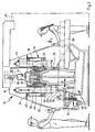
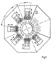
- Embodiment of a multi-spindle lathe includes a Machine frame 12 on which a spindle drum 14 around a vertical drum axis 16 is rotatably supported.
- the rotating bearing of the spindle drum 14 by a bearing unit 18 not described in detail realized, the bearing unit 18 on a column 20 of the machine frame is supported so that the column 20 carries the spindle drum 14 via the bearing unit 18 and rotatably. It is also used to fix the spindle drum 14 serration in individual rotary positions 22 provided.
- the drive motor 28 is so by means of an NC controller 29 controllable that the rotation of the spindle drum 14 by exactly definable angular steps S is possible.
- the storage of the spindle drum 14 does not have to be as shown Embodiment on the column 20 of the Machine frame 12 take place, but can also be circumferential the spindle drum 14 take place, such as this in German patent applications 195 04 369.3 and 195 04 371.5 is shown, to which hereby the full content Reference is made.
- the spindle drum 14 in turn comprises a lower one Guide flange 32 and an upper guide flange 34 which a plurality of workpiece spindles 40 in the direction its vertical spindle axis 42 is slidably mounted, the spindle axis 42 preferably parallel to the drum axis 16 runs, but also in relation to this by one acute angle can be inclined.
- Each of the workpiece spindles 40 contributes to its front one vertical workpiece spindles lower end of a workpiece holder 46 for receiving a workpiece 50 to be machined, the workpiece holder 46, for example, as a chuck is formed, but also for example in the form a collet can be formed.
- the in the workpiece holders 46 of the workpiece spindles 40 Workpieces held are provided in processing stations Tools 52 and / or 54 arranged facing, wherein the tools 52 and / or 54 on a tool slide 60 sit, which in turn can be moved linearly in a direction 62 is.
- the direction 62 runs transversely, preferably vertically to the spindle axis 42 of that workpiece spindle 40, which is in a spindle position, in which a machining with tools 52 or 54 of the tool slide 60 is possible.
- Each tool slide 60 is a machining station in turn still arranged on a machine frame 12 Carriage guide 64 and stored as a Whole designated 66 and by the NC controller 29th controlled linear drive, which preferably has a drive motor 68, which in turn has a Transmission a not shown in detail in the drawing Spindle drive for moving the tool slide 60 drives.
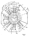
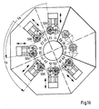
- stations 1 to 8 are provided, for example the stations 1 to 6 processing stations and the stations 7 and 8 for example loading and unloading stations for loading and Unload the workpieces 50 are.
- a single tool slide 60 1 to 60 6 is arranged in each of the processing stations 1 to 6 and can be moved in the corresponding direction 62 1 to 62 6 .
- the tool slides 60 1 to 60 6 are arranged in the machining stations 1 to 6 such that their center or symmetry axis 70 1 to 70 6 are arranged at successive tool slides 60 1 to 60 6 at an angular distance ⁇ from one another, which in the case of the total eight stations 1 to 8 is 45 ° each.
- the spindle drum 14 is the same in number Angular distances ⁇ from each other arranged workpiece spindles 40, which corresponds to the number of stations 1 to 8, so that in the case of 8 stations also 8 workpiece spindles 40 are arranged on the spindle drum 14.
- each of the stations 1 to 8 is only assigned a single spindle position, but each of the Stations 1 to 8 have two spindle positions 1.1 and 1.2 or 2.1 and 2.2 ... 8.1 and 8.2 in which the workpiece spindles 40 of the spindle drum 14 can be positioned.
- first spindle position 1.1 ... 8.1 and the second spindle position 1.2 ... 8.2 the respective station 1 ... 8 each at the same angular distance ⁇ are arranged from each other during the second spindle position 1.2 ... 8.2 compared to the next following first spindle position 2.1 ... 1.1 the next one Stations is arranged at an angular distance ⁇ , which also between all successive second Spindle positions 1.2 ... 8.2 and the following first Spindle positions 2.1 ... 1.1. is always the same.
- the angle ⁇ is half the angle ⁇ so that in the described embodiment ⁇ is equal to 15 ° and ⁇ is 30 ° because the angular distance y is 45 °.
- At least one tool 54 1.1 is assigned to each of the spindle positions 1.1, 1.2 ... 6.1, 6.2, the two tools 54 1.1 and 54 1.2 are mounted as stationary tools on the same slide 60 1 and can therefore only be moved together in the direction 62.
- Each tool moves on its own tool path 53 1.1 or 53 1.2 running parallel to direction 62.
- Direction 62 preferably extends in each of the processing stations 1 to 6 parallel to one between the two Spindle positions 1.1 and 1.2 lie in the radial direction Drum axis 16, the radial direction in particular symmetrical between the two spindle positions 1.1 and 1.2 lies and coincides with the line of symmetry 70. The same applies to all other processing stations 2 to 6.
- a particularly preferred embodiment provides not only one tool 54 1.1 or 54 1.2 on the respective slide 60 1 for each spindle position 1.1 and 1.2 of a machining station, but additionally one further tool each also moving along the respective tool path 53 1.1 or 53 1.2 Tool, namely the tools 52 1.1 or 52 1.2 , whereby by moving the slide 60 in the direction 62 either one of the tools 54 or one of the tools 52 can be used on the workpiece 50 in the respective spindle position 1.1 or 1.2.
- the tools 54 are External turning tools, while the tools 52 are Boring bars. However, they are also all different types Tools can be used.
- a workpiece spindles 40 are first turned during a first period t 1 by rotating the spindle drum 14 by angular steps S 3 of the same size ⁇ , which are always the same size Always positioned in the first spindle positions 1.1, 2.1, 3.1, 4.1, 5.1, 6.1, 7.1, 8.1 (shown in solid lines in Fig. 3) of the stations 1 to 8, so that in the processing stations 1 to 6 processing of the workpieces 50 by means of tools 52 1.1 to 52 6.1 and / or 54 1.1 to 54 6.1 .
- a workpiece cycle comprises eight identical sequences of steps, each sequence of steps comprising an angular step S 3 .
- Stations 7 and 8 are designed as loading and unloading stations, whereby the feed and Workpieces 50 are removed.
- the workpiece transport system 80 is to be designed so that it is in a Spindle position of a station, for example the spindle position 7.1, the processed workpieces 50 for removal and in the spindle position 8.1 of the next station 8 provides the raw workpieces 50 for transfer, one Access by a Z-axis movement of the workpiece spindle 40 with the workpiece holder 46.
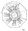
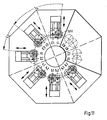
- the multi-spindle lathe can continue to work, since a rotation of the spindle drum 14 by an angle step S 1 corresponding to the angle ⁇ opens up the possibility to further process the workpieces 50 in the second spindle positions 1.2 to 6.2 (drawn with solid lines in FIG. 4) of the processing stations (1 to 6).
- the second spindle positions 1.2 to 6.2 are provided with the same tools 52 and 54 as the first spindle positions 1.1 to 6.1, so that the machining over a second period t 2 until the tools wear out while maintaining the angular steps S 3 of the size ⁇ 52 and 54 can be continued in the second spindle positions 1.2 to 6.2.
- the workpiece transport system must be set up in this way be that workpieces 50 also in the second spindle positions 7.2 and 8.2 of stations 7 and 8 can be removed and fed are.
- Table 1 shows that depending on the design of the handling 12 or 14 tools 52 or 54 or tool pairs 52 and 54 can be used to machine the workpieces 50.
- a second and at the same time simple variant of the method according to the invention for machining workpieces 50 in all spindle positions provides that, for example, starting with machining the workpiece 50 in the first spindle position 1.1 of the machining station 1, first machining the workpiece 50 externally is carried out with the tool 54 1.1 and is then processed with the tool 52 1.1 using the slide 60 1 method.
- the spindle drum 14 is then rotated in the form of a first angular step S 1 such that the workpiece 50 is no longer in the first spindle position 1.1 but in the second spindle position 1.2 of the machining station 1 and can also be machined in the latter by means of the tools 52 and 54.
- such a procedure is advantageous if as many tools as possible are used should be, with two in each processing station Sets of tools 52 and 54 are provided so that by switching from the first spindle position 1.1 to the second spindle position 1.2 and further processing with Tools 52 and 54 doubled the number of possible tools can be, in contrast to that from the state of the Technology known multi-spindle lathe, in which without special measures in one processing station in only one Spindle position can be processed.
- Table 1 shows that the second variant of the inventive method not only the use of Stations 7 and 8 as input-output stations but also at Only station 8 can be used as an input / output station is.
- the solution according to the invention can be particularly advantageous then use when in the lathe according to the invention machining a front and a back should be done.
- the workpieces 50 are clamped on different sides.
- a workpiece 50V hatchched in azimuth
- a workpiece 50R hatched in radially
- the workpiece 50V is then clamped in the workpiece spindle 40 3 for machining on the front side, in the workpiece spindle 40 4 the workpiece 50R is clamped for machining the rear side, and so on up to the workpiece spindle 40 8 .
- successive workpiece spindles 40 1 ... 40 8 are alternately provided with workpieces 50V and 50R.
- sequence of steps and the angular steps correspond to those of second variant of the method according to the invention and result 6 and Table 1 together with the number of maximum usable tools depending on the number the loading and unloading stations.
- each of the workpieces 50V and 50R passes through all spindle positions 1.1, 1.2, 2.1, .. to 6.2, so that each of the tools 52 and 54 must be designed so that it is suitable for front and back machining.
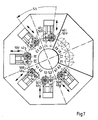
- workpieces 50 1 to 40 8 work pieces 50V and 50 R are also clamped in workpiece spindles 40 1 to 40 8 successive in the azimuthal direction in the manner already described in connection with FIG. 7 ,
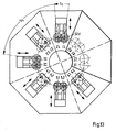
- the spindle drum 14 passes through for example, initially in the first spindle position 1.1 the first station 1 standing workpiece 50V first spindle position 1.1 and the second spindle position 1.2 the first processing station and then the first spindle position 2.1 of the second processing station.
- a workpiece that can be machined on its front runs through 50V thus the spindle positions 1.1 and 1.2, 2.1, 3.1 and 3.2, 4.1, 5.1 and 5.2, 6.1 of all processing stations 1 to 6 and skips the second spindle positions 2.2, 4.2 and 6.2.
- the workpiece 50R which is intended for machining the rear side, and for example the sequence of steps with the workpiece spindle 40 2 in the first spindle position 2.1 of the machining station 2, starts.
- the switching steps S1, S2 and S3 have the effect that the spindle positions 2.1, 2.2, 3.1, 4.1, 4.2, 5.1, 6.1, 6.2 and 7.1 are reached during one revolution, but not the spindle positions 1.2, 3.2, 5.2. Comparing Fig. 9 and Fig.
- tools 52 and 54 can be provided in the spindle positions 1.2, 3.2 and 5.2, which are used only for machining the workpieces 50V, while in the spindle positions 2.2, 4.2 and 6.2 workpieces can be provided, which are used exclusively for the processing of workpieces 50R, since this spindle position cannot be reached by the workpieces 50V.
- the step sequence comprises the angular steps S 1 , S 2 and S 3 and the workpiece cycle comprises, for example, four such identical step sequences.
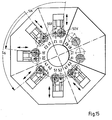
- a first angular step S 4 is carried out in such a way that the workpiece 50V is moved from the machining position 1.1 into the spindle position 2.2 and then into the machining position 3.1 by means of an angular step S 2 , it can be seen As shown in FIG. 12, the same angular steps S 4 and S 2 applied to the workpiece 50R in the spindle position 2.1 have the consequence that this first moves into the spindle position 3.2 and then the spindle position 4.1.
- the workpiece travels 50R total the spindle positions 1.2, 2.1, 3.2, 4.1, 5.2 and 6.1, but not the spindle positions 1.1, 2.2, 3.1, 4.2, 5.1 and 6.2, so that in total in each Spindle positions 1.1 to 6.2 either machining a of the workpieces 50V or one of the workpieces 50R can, so that also in these individual spindle positions usable tools 52 and 54 for the individual machining tasks either the front of a 50V workpiece or the back of a 50R workpiece can.
- the sequence of steps in the sixth variant comprises the angular steps S 2 and S 4 , four such sequences of steps resulting in a workpiece cycle.
- a complete division of the front side machining and the rear side machining into the individual spindle positions 1.1 to 6.2 of the machining stations 1 to 6 can also be achieved, if, as shown in FIGS. 13 and 14, the workpiece 50V starting from the spindle position 1.1 is brought into the spindle position 1.2 by an angular step S 1 , but then through an angular step S 5 into the spindle position 3.1, then again through a switching step S 1 into the spindle position 3.2, etc.
- the workpiece 50R starting in the spindle position 2.1, only reaches the spindle position 2.2, 4.1 and 4.2 and 6.1 and 6.2, but not the spindle positions 1.1 and 1.2, 3.1 and 3.2, 5.1 and 5.2 of the processing stations 1, 3 and 5, which are reached by the workpiece 50V.
- the sequence of steps comprises the angular steps S 1 and S 5 and a total of four such sequences of steps result in a tool cycle.
- the spindle drum 14 is rotated through angular steps S 6 , so that when the workpieces 50V and 50R are arranged in the workpiece spindles 40 1 ...
- an angle step S 1 changes from machining the workpieces 50V and 50R in the first spindle positions 1.1 to 6.1 to machining the workpieces 50V and 50R changed in the second spindle positions 1.2 to 6.2.
- the step sequence only includes the angular step S 6 , so that four identical step sequences result in a workpiece cycle, the number of tools that can be used also being 6 for the eighth variant if only one of the tools 52 or 54 is used, as shown in Table 1 and Fig. 6 is shown.
Landscapes
- Engineering & Computer Science (AREA)
- Mechanical Engineering (AREA)
- Turning (AREA)
Claims (52)
- Tour multibroche comprenant un bâti machine (12), un tambour à broches (14), disposé de façon à pouvoir tourner autour d'un axe de tambour (16) par rapport au bâti machine (12), avec une pluralité de broches d'outil (40) disposées sous des espacements angulaires (γ) définis par rapport à l'axe de tambour (16) et déplaçables par rapport au bâti machine (12) dans une direction de circulation (23) à l'occasion d'une rotation du tambour de broche (14), broches d'outil qui sont chacune munies d'un réceptacle de pièce (46), pour une pièce (50), et comprennent un nombre, de postes (1 à 8) correspondant à la pluralité de broches à pièce (40), disposés sur le bâti machine (12) en se suivant les uns les autres dans la direction périphérique des broches à pièce, les postes comprenant au moins un poste d'usinage (1 à 6),
caractérisé en ce que
le au moins un poste d'usinage (1 à 6) présente, pour assurer l'usinage des pièces (50), une première et une deuxième position de broche (1.1, 1.2; ...; 6.1, 6.2), qui par rapport à l'axe de tambour (16) sont disposées les unes par rapport aux autres selon un espacement angulaire (α), en ce que le tambour à broche (14) est susceptible de tourner de manière qu'une broche à pièce (40) chargée avec une pièce (50) est susceptible d'être positionnée dans chacune des positions de broche (1.1, 1.2; ...; 6.1, 6.2), et en ce qu'à chaque position de broche (1.1, 1.2; ...; 6.1, 6.2), est associé un outil d'usinage (52, 54) propre. - Tour multibroche selon la revendication 1, caractérisé en ce qu'au moins deux des postes (1 à 8) sont réalisés sous la forme de postes d'usinage, avec chaque fois une première (1.1 à 6.1) et une deuxième position de broche (1.2 à 6.2).
- Tour multibroche selon l'une des revendications précédentes, caractérisé en ce que les autres postes (1 à 8) présentent au moins une position de broche qui présente un espacement angulaire (γ) par rapport à une première ou une deuxième position de broche du au moins un poste d'usinage, espacement angulaire correspondant à un multiple entier de 360°, divisé par le nombre des broches à pièce (40).
- Tour multibroche selon l'une des revendications précédentes, caractérisé en ce que tous les postes (1 à 8) présentent chacun le même nombre de positions de broche (1.1, 1.2; ...; 8.1, 8.2).
- Tour multibroche selon la revendication 4, caractérisé en ce que les premières positions de broche (1.1 ... 8.1), se suivant les unes les autres dans la direction de circulation (23) de tous les postes (1 à 8), ont un espacement angulaire (γ) de 360°, divisé par le nombre des broches à pièce (40).
- Tour multibroche selon la revendication 4 ou 5, caractérisé en ce que les deuxièmes positions (1,2 ... 8.2) se suivant en direction de circulation 823) de tous les postes (1 à 8) ont un espacement angulaire (γ) de 360°, divisé par le nombre des broches à pièces (40).
- Tour multibroche selon l'une des revendications précédentes, caractérisé en ce que les outils (52, 54) associés à la première position de broche (1.1 ... 6.1) et à la deuxième position de broche (1.2 ... 6.2) du au moins un poste d'usinage (1 à 6) sont déplaçables sur des trajectoires d'outil (53) parallèles entre elles.
- Tour multibroche selon la revendication 7, caractérisé en ce que les trajectoires d'outils (53) parallèles s'étendent, parallèlement à une direction radiale par rapport à l'axe de tambour (16), la direction radiale étant située entre la première position de broche (1.1 ... 6.1) et la deuxième position de broche (1.2 ... 6.2).
- Tour multibroche selon l'une des revendications précédentes, caractérisé en ce que l'outil (52, 54) associé à chaque position de broche (1.1 ... 6.2), en se référant à la broche à pièce (40) placée dans cette position de broche (1.1 ... 6.2), est déplaçable en une direction X par rapport à celle-ci.
- Tour multibroche selon la revendication 9, caractérisé en ce que, en se référant à une position de référence fixe par rapport à la broche à pièce de la pièce (40), la direction X est tournée d'un angle dans la deuxième position de broche (1.2 ... 6.2) par rapport à la première position de broche (1.1 ... 6.1), et en ce qu'une commande (29), calculant les coordonnées d'un usinage de la pièce (50), prend en considération la rotation.
- Tour multibroche selon l'une des revendications précédentes, caractérisé en ce que les outils (52, 54) associés à la première position de broche (1.1 ... 6.1) et à la deuxième position de broche (1.2 ... (6.2) du poste d'usinage (1 à 6) sont positionnables par un dispositif de positionnement (60) commun.
- Tour multibroche selon la revendication 11, caractérisé en ce que les outils (51.1.1, 52.1.2; 54.1.1, 54.1.2), associés à la première position de broche (1.1 ... 6.1) et à la deuxième position de broche (1.2 ... 6.2) du poste d'usinage (1 à 6), sont déplaçables simultanément par le dispositif de positionnement (60).
- Tour multibroche selon la revendication 12, caractérisé en ce que le dispositif de positionnement (60) est un chariot porte-outil, sur lequel sont disposés les outils (52, 54) associés à la première position de broche (1.1 ... 6.1) et la deuxième position de broche (1.2 ... 6.2) du poste d'usinage (1 à 6).
- Tour multibroche selon la revendication 12 ou 13, caractérisé en ce que les outils (52, 54) sont reliés de façon solidaire au dispositif de positionnement (60).
- Tour multibroche selon l'une des revendications 11 à 14, caractérisé en ce que le dispositif de positionnement (60) est déplaçable transversalement par rapport à l'axe de tambour (16).
- Tour multibroche selon la revendication 15, caractérisé en ce que le dispositif de fonctionnement (60) est déplaçable dans une direction radiale par rapport à l'axe de tambour (16).
- Tour multibroche selon l'une des revendications précédentes, caractérisé en ce que deux outils (52, 54) sont associés à chaque position de broche (1.1 ... 6.2).
- Tour multibroche selon la revendication 17, caractérisé en ce que les deux outils (52, 54) associés à une position de broche (1.1 ... 6.2) sont déplaçables conjointement.
- Tour multibroche selon la revendication 17 ou 18, caractérisé en ce que les deux outils (52 ,54) associés à une position de broche (1.1 ... 1.2) sont déplaçables le long d'une trajectoire d'outil (53) commune.
- Tour multibroche selon l'une des revendications précédentes, caractérisé en ce que la première position de broche (1.1 ... 6.1) et la deuxième position de broche (1.2 ... 6.2) du au moins un poste d'usinage (1 à 6) présentent un espacement angulaire (α) l'une de l'autre, qui est différent de l'espacement angulaire (β) entre deux positions de broche directement successives de deux postes différents.
- Tour multibroche selon la revendication 20, caractérisé en ce que la première position de broche (1.1 ... 6.1) et la deuxième position de broche (1.2 ... 6.2) du au moins un poste d'usinage (1 à 6) présentent un espacement angulaire (α) l'un par rapport à l'autre, qui est inférieur à 360°, divisé par le nombre des positions de broche (1.1 ... 8.2) de tous les postes (1 à 8).
- Tour multibroche selon la revendication 20 ou 21, caractérisé en ce que la première position de broche (1.1 ... 8.1) et la deuxième position de broche (1.2 ... 8.2) présentent un espacement angulaire (α) l'un de l'autre, qui correspond à une fraction en nombre entier de l'espacement angulaire (β) entre deux positions de broche (1.2, 2.1; ; 7.2; 8.1) directement successives de deux postes (1.2; ...; 7, 8) se suivant directement.
- Tour multibroche selon l'une des revendications précédentes, caractérisé en ce que l'espacement angulaire (α) entre la première position de broche et la deuxième position de broche est choisi tel que la pièce (50) placée en l'une des positions de broche (1.1 ... 6.2) est susceptible d'être usinée sans collision par rapport à l'outil (52, 54) situé en l'autre position de broche (1.1 ... 6.2).
- Tour multibroche selon l'une des revendications précédentes, caractérisé en ce que les broches à pièce (40) et les postes (1 à 8) sont disposées sous des espacements angulaires (γ) constants les uns par rapport aux autres sur le tambour de broche (14).
- Tour multibroche selon l'une des revendications précédentes, caractérisé en ce que les broches à pièce (40) sont déplaçables dans la direction de leurs axes de broche (42) par rapport au tambour de broche (14), afin d'obtenir un déplacement selon l'axe Z pour l'usinage de la pièce (50).
- Tour multibroche selon l'une des revendications précédentes, caractérisé en ce que la totalité des premières positions de broche (1.1 ... 6.1) de tous les postes d'usinage (1 à 6) et la totalité des deuxièmes positions de broche (1.2 ... 6.2) de tous les postes d'usinage (1 à 6) présentent un jeu propre d'outils (52, 54).
- Tour multibroche selon l'une des revendications précédentes, caractérisé en ce que des broches à pièce (40) disposées à la suiLe les unes des autres en direction périphérique (23) sont munies en alternance d'un réceptacle (46) pour une première face et d'un réceptacle (46) pour une deuxième face de la pièce 850).
- Tour multibroche selon la revendication 27, caractérisé en ce que toutes les positions de broche (1.1 ... 6.2) de tous les postes d'usinage (1 à 6) présentent des outils (52, 54), tant pour la première face que pour la deuxième face de la pièce (50).
- Tour multibroche selon la revendication 27, caractérisé en ce que l'une des positions de broche (1.1 ... 6.2) du au moins un poste d'usinage (1 à 6) présente un outil (52, 54) usinant exclusivement l'une des faces de la pièce (50).
- Tour multibroche selon l'une la revendication 29, caractérisé en ce que dans l'autre position de broche (1.1 ... 6.2) du poste d'usinage (1 à 6) est disposé un outil (52, 54) usinant les deux faces de la pièce (50).
- Tour multibroche selon la revendication 29, caractérisé en ce que, dans l'autre position de broche (1.1 ... 6.2) du poste d'usinage (1 à 6) est disposé un outil (52, 54), usinant exclusivement l'autre face de la pièce (50).
- Tour multibroche selon la revendication 29, caractérisé en ce que, caractérisé en ce que, aux deux positions de broche (1.1, 1.2; ... 6.1, 6.2) d'un des postes d'usinage (1 à 6), sont associés des outils (52, 54) pour usiner uniquement la première face de la pièce (50) et, aux deux positions de broche (1.1, 1.2; ... 6.1, 6.2) d'un autre poste d'usinage (1 à 6), sont associés des outils (52, 54) pour usiner uniquement la deuxième face de la pièce (50).
- Tour multibroche selon la revendication 32, caractérisé en ce que l'autre poste d'usinage (1 à 6) est un poste d'usinage qui suit un poste d'usinage (1 à 6).
- Procédé de fabrication de pièce tournée, pour lequel les pièces tournées se présentant sous forme d'ébauche, sont logées dans des réceptacles pour pièce d'une pluralité de broches à pièce disposées sur un tambour de broche et déplaçables dans une direction de circulation autour d'un axe de tambour de broche, en cas de rotation de ceux-ci, et sont usinées en au moins un poste d'usinage, le poste d'usinage étant formé d'un nombre, correspondant au nombre de broches à pièce, de postes successifs, disposés les uns à la suite des autres sur le bâti machine, caractérisé en ce que, dans le poste d'usinage, est effectué un premier usinage avec un premier outil dans une première position de broche et un deuxième usinage avec un deuxième outil dans une deuxième position de broche, disposée sous un espacement angulaire par rapport à la première position de broche dans la direction de circulation.
- Procédé selon la revendication 34, caractérisé en ce que chacun des postes est muni d'une première position de broche et d'une deuxième position de broche et les premières positions de broche et les deuxièmes positions de broche sont chacune disposées les unes au-dessous des autres sous des espacements angulaires identiques.
- Procédé selon la revendication 34 ou 35, caractérisé en ce qu'une pièce est fabriquée au moyen d'un cycle de travail de pièce, qui présente au moins une succession d'étapes, avec au moins une étape de mouvement angulaire, concernant la rotation du tambour de broche.
- Procédé selon la revendication 36, caractérisé en ce que le cycle de pièce comprend plusieurs successions d'étapes identiques.
- Procédé selon la revendication 36 ou 37, caractérisé en ce chaque succession d'étapes comprend plusieurs étapes de mouvement angulaire de valeurs différentes.
- Procédé selon l'une des revendications 35 à 37, caractérisé en ce que le cycle de travail de pièce est achevé après passage d'un nombre déterminé de postes.
- Procédé selon l'une des revendications 36 à 39, caractérisé en ce que la somme des étapes de mouvement angulaire d'une succession d'étapes est un multiple entier de 360°, divisé par le nombre des broches à pièce.
- Procédé selon l'une des revendications 36 à 40, caractérisé en ce que, en cas d'exécution des cycles de travail de pièce, pendant un premier intervalle de temps, ce sont les premières positions de broche qui font l'objet d'un accostage avec les broches à pièce et, ensuite, ce sont seulement les deuxièmes positions de broche qui font l'objet d'un accostage, pendant un deuxième intervalle de temps.
- Procédé selon la revendication 41, caractérisé en ce que le premier intervalle de temps est déterminé par l'utilisation des outils montés aux premières positions de broche.
- Procédé selon la revendication 41 ou 42, caractérisé en ce que le deuxième intervalle de temps est déterminé par l'utilisation des outils montés aux deuxièmes positions de broche.
- Procédé selon l'une des revendications 41 à 43, caractérisé en ce que, après écoulement du premier intervalle de temps, une rotation du tambour de broche est effectuée pour procéder au changement de positionnement des broches à pièce, avec passage des positions en rotation, tombant sur les premières positions de broche, aux positions en rotation tombant sur les deuxièmes positions de broche.
- Procédé selon l'une des revendications 34 à 39, caractérisé en ce que toutes les positions de broche se suivant en direction de circulation sont franchies les unes après les autres dans la direction de circulation par les différentes broches à pièce.
- Procédé selon l'une des revendications 34 à 45, caractérisé en ce que les pièces sont usinées sur une première face et sur une deuxième face.
- Procédé selon la revendication 46, caractérisé en ce que, avec au moins l'une des étapes de mouvement angulaire de la succession d'étapes, est sautée une position de broche faisant immédiatement suite en direction de circulation.
- Procédé selon la revendication 47, caractérisé en ce que, avec au moins l'une des étapes de mouvement angulaire de la succession d'étapes n'est sautée que la position de broche faisant immédiatement suite dans la direction de circulation.
- Procédé selon la revendication 47, caractérisé en ce que, avec l'étape de mouvement angulaire, sont sautées les deux positions de broche se faisant immédiatement suite en direction de circulation.
- Procédé selon la revendication 47, caractérisé en ce que, avec l'étape de mouvement angulaire, sont sautées les trois positions de broche se faisant immédiatement suite en direction de circulation.
- Procédé selon la revendication 47 à 50, caractérisé en ce que chacune des étapes de mouvement angulaire d'une succession d'étapes sert à sauter une position de broche immédiatement suivante.
- Procédé selon l'une des revendications 47 à 50, caractérisé en ce que, avec l'une des étapes de mouvement angulaire, est effectué un changement, d'une position de broche à une position de broche immédiatement suivante en direction de circulation.
Applications Claiming Priority (2)
| Application Number | Priority Date | Filing Date | Title |
|---|---|---|---|
| DE19619720 | 1996-05-15 | ||
| DE19619720A DE19619720A1 (de) | 1996-05-15 | 1996-05-15 | Mehrspindeldrehmaschine |
Publications (3)
| Publication Number | Publication Date |
|---|---|
| EP0807490A2 EP0807490A2 (fr) | 1997-11-19 |
| EP0807490A3 EP0807490A3 (fr) | 1999-01-27 |
| EP0807490B1 true EP0807490B1 (fr) | 2002-11-20 |
Family
ID=7794460
Family Applications (1)
| Application Number | Title | Priority Date | Filing Date |
|---|---|---|---|
| EP97107410A Expired - Lifetime EP0807490B1 (fr) | 1996-05-15 | 1997-05-06 | Tour multibroche |
Country Status (5)
| Country | Link |
|---|---|
| US (1) | US6000305A (fr) |
| EP (1) | EP0807490B1 (fr) |
| JP (1) | JPH1043907A (fr) |
| DE (2) | DE19619720A1 (fr) |
| ES (1) | ES2185833T3 (fr) |
Families Citing this family (16)
| Publication number | Priority date | Publication date | Assignee | Title |
|---|---|---|---|---|
| JP3636895B2 (ja) * | 1998-09-02 | 2005-04-06 | 株式会社森精機ハイテック | 主軸移動型立形工作機械用の棒状工作物供給装置および主軸移動型立形工作機械における棒状工作物供給方法 |
| DE19916212C2 (de) | 1999-04-10 | 2003-07-10 | Schuette Alfred H Gmbh & Co Kg | Mehrspindelige Werkzeugmaschine, insbesondere Mehrspindeldrehautomat |
| AUPQ120499A0 (en) * | 1999-06-25 | 1999-07-22 | K D Binnie Engineering Pty Ltd (As Trustees For K D Binnie Engineering Superannuation Fund) | A lathe |
| US6446533B2 (en) * | 1999-08-20 | 2002-09-10 | Toshiharu Tom Miyano | Lathe assembly and method of using a lathe assembly |
| EP1106304B1 (fr) * | 1999-12-01 | 2006-03-08 | Index-Werke Gmbh & Co. Kg Hahn & Tessky | Machine-Outil |
| US20040069106A1 (en) * | 2002-10-14 | 2004-04-15 | Mcadoo David L. | Linear feed cutting apparatus and method |
| US20050076759A1 (en) * | 2003-10-08 | 2005-04-14 | Brian Westfall | Linear saw with stab-cut bevel capability |
| US7647133B2 (en) * | 2005-10-12 | 2010-01-12 | Alpine Engineered Products, Inc. | Method and apparatus for optimization of cutting lumber |
| IT1396170B1 (it) * | 2008-09-11 | 2012-11-16 | Gildemeister Spa | Macchina tornitrice plurimandrino con mandrini portapezzo movibili in direzione longitudinale all'asse macchina |
| DE102009048012A1 (de) * | 2009-10-02 | 2011-04-14 | Kapp Gmbh | Verfahren zum Betreiben einer Verzahnungs- oder Profilschleifmaschine und Verzahnungs- oder Profilschleifmaschine |
| ITTO20090809A1 (it) * | 2009-10-23 | 2011-04-24 | Siecab S R L | Stazione di lavoro perfezionata per lavorazioni ad asportazione di truciolo |
| ITTO20121148A1 (it) * | 2012-12-27 | 2014-06-28 | Siecab S R L | Tornio verticale con mandrino pick-up mobile lungo una traiettoria circolare |
| DE102014106915B4 (de) * | 2014-05-16 | 2024-10-02 | K.R. Pfiffner Gmbh | Werkzeugmaschine und Verfahren zum Betreiben einer Werkzeugmaschine |
| CZ307124B6 (cs) * | 2015-08-20 | 2018-01-24 | ÄŚVUT v Praze, Fakulta strojnĂ | Způsob provádění alespoň dvou po sobě následujících operací na obráběcím stroji |
| IT201800011170A1 (it) | 2018-12-17 | 2020-06-17 | Hgears Holding Gmbh | Metodo e macchina utensile per la realizzazione di ingranaggi e componenti dentati provvisti di dentatura esterna e profilo scanalato interno |
| CN111804954A (zh) * | 2020-07-22 | 2020-10-23 | 龙岩畅通机械设备有限公司 | 一种快速多工位钻管接头专机 |
Family Cites Families (7)
| Publication number | Priority date | Publication date | Assignee | Title |
|---|---|---|---|---|
| US2140019A (en) * | 1937-04-01 | 1938-12-13 | Baird Machine Co | Positioning device |
| US3404589A (en) * | 1966-10-31 | 1968-10-08 | Pneumo Dynamics Corp | Indexible multiple spindle lathe |
| CH507763A (de) * | 1969-12-03 | 1971-05-31 | Eunipp Ag | Mehrspindel-Drehmaschine |
| CH581518A5 (fr) * | 1975-03-14 | 1976-11-15 | Eunipp Ag | |
| DE2517759A1 (de) * | 1975-04-22 | 1976-11-04 | Index Werke Kg Hahn & Tessky | Mehrspindeldrehautomat |
| US5083485A (en) * | 1986-10-09 | 1992-01-28 | Index-Werke Gmbh & Co. Kg Hahn & Tessky | Method and apparatus for machining both sides of workpieces |
| DE19504370A1 (de) * | 1995-02-10 | 1996-08-14 | Index Werke Kg Hahn & Tessky | Mehrspindeldrehmaschine |
-
1996
- 1996-05-15 DE DE19619720A patent/DE19619720A1/de not_active Ceased
-
1997
- 1997-05-06 EP EP97107410A patent/EP0807490B1/fr not_active Expired - Lifetime
- 1997-05-06 DE DE59708745T patent/DE59708745D1/de not_active Expired - Fee Related
- 1997-05-06 ES ES97107410T patent/ES2185833T3/es not_active Expired - Lifetime
- 1997-05-13 US US08/855,356 patent/US6000305A/en not_active Expired - Lifetime
- 1997-05-14 JP JP9124413A patent/JPH1043907A/ja active Pending
Also Published As
| Publication number | Publication date |
|---|---|
| JPH1043907A (ja) | 1998-02-17 |
| US6000305A (en) | 1999-12-14 |
| EP0807490A3 (fr) | 1999-01-27 |
| DE59708745D1 (de) | 2003-01-02 |
| DE19619720A1 (de) | 1997-11-20 |
| ES2185833T3 (es) | 2003-05-01 |
| EP0807490A2 (fr) | 1997-11-19 |
Similar Documents
| Publication | Publication Date | Title |
|---|---|---|
| EP1193027B1 (fr) | Tour | |
| EP1834719B1 (fr) | Machine-outil et procédé destiné au traitement par enlèvement de copeaux de pièces usinées, en particulier de pièces usinées métalliques | |
| EP0807490B1 (fr) | Tour multibroche | |
| EP0538515A1 (fr) | Tour | |
| EP1409182B1 (fr) | Machine-outil | |
| EP1180407B1 (fr) | Machine-outil | |
| DE19504368A1 (de) | Werkzeugmaschine | |
| EP0834379B1 (fr) | Tour | |
| DE4236866A1 (de) | Drehmaschine | |
| EP1511596B1 (fr) | Tour multibroche | |
| EP0755315B1 (fr) | Tour multibroche | |
| DE10130760A1 (de) | Drehmaschine | |
| DE102016110617A1 (de) | Verfahren zum Bearbeiten mehrerer Werkstücke auf einem drehbaren Werkstückträger sowie Werkstückträger und Bearbeitungsmaschine hierfür | |
| DE4022572A1 (de) | Drehmaschine mit doppelrevolver | |
| DE4330858C1 (de) | Verfahren zum Bearbeiten eines Werkstückes auf einem CNC-Drehautomaten sowie CNC-Drehautomat | |
| AT521951A4 (de) | Werkzeugmaschine | |
| DE10206949C1 (de) | Zweispindel-Drehmaschine | |
| EP0028705A1 (fr) | Procédé d'usinage par enlèvement de copeaux d'une pièce métallique rotative symétriquement et dispositif pour la mise en oeuvre de ce procédé | |
| DE102006048896B3 (de) | Werkzeugmaschine | |
| DE102009053679A1 (de) | Werkzeugmaschine zur Bearbeitung eines rohrförmigen Werkstücks | |
| DE10107660B4 (de) | Langdrehautomat mit Rundtaktmaschine | |
| DE10104181A1 (de) | Drehmaschine | |
| EP1311362A1 (fr) | Unite d'usinage et de verification pour la construction de machines automatiques speciales et de transfert lineaire | |
| DE102020134737A1 (de) | Bearbeitungsmaschine | |
| DE2431688A1 (de) | Drehautomat |
Legal Events
| Date | Code | Title | Description |
|---|---|---|---|
| PUAI | Public reference made under article 153(3) epc to a published international application that has entered the european phase |
Free format text: ORIGINAL CODE: 0009012 |
|
| AK | Designated contracting states |
Kind code of ref document: A2 Designated state(s): CH DE ES FR GB IT LI |
|
| PUAL | Search report despatched |
Free format text: ORIGINAL CODE: 0009013 |
|
| AK | Designated contracting states |
Kind code of ref document: A3 Designated state(s): CH DE ES FR GB IT LI |
|
| 17P | Request for examination filed |
Effective date: 19990320 |
|
| GRAG | Despatch of communication of intention to grant |
Free format text: ORIGINAL CODE: EPIDOS AGRA |
|
| 17Q | First examination report despatched |
Effective date: 20010523 |
|
| GRAG | Despatch of communication of intention to grant |
Free format text: ORIGINAL CODE: EPIDOS AGRA |
|
| GRAH | Despatch of communication of intention to grant a patent |
Free format text: ORIGINAL CODE: EPIDOS IGRA |
|
| GRAH | Despatch of communication of intention to grant a patent |
Free format text: ORIGINAL CODE: EPIDOS IGRA |
|
| GRAA | (expected) grant |
Free format text: ORIGINAL CODE: 0009210 |
|
| AK | Designated contracting states |
Kind code of ref document: B1 Designated state(s): CH DE ES FR GB IT LI |
|
| REG | Reference to a national code |
Ref country code: GB Ref legal event code: FG4D Free format text: NOT ENGLISH |
|
| RTI1 | Title (correction) |
Free format text: MULTIPLE-SPINDLE LATHE |
|
| REG | Reference to a national code |
Ref country code: CH Ref legal event code: EP |
|
| REF | Corresponds to: |
Ref document number: 59708745 Country of ref document: DE Date of ref document: 20030102 |
|
| REG | Reference to a national code |
Ref country code: CH Ref legal event code: NV Representative=s name: KIRKER & CIE SA |
|
| GBT | Gb: translation of ep patent filed (gb section 77(6)(a)/1977) |
Effective date: 20030315 |
|
| REG | Reference to a national code |
Ref country code: ES Ref legal event code: FG2A Ref document number: 2185833 Country of ref document: ES Kind code of ref document: T3 |
|
| ET | Fr: translation filed | ||
| PLBE | No opposition filed within time limit |
Free format text: ORIGINAL CODE: 0009261 |
|
| STAA | Information on the status of an ep patent application or granted ep patent |
Free format text: STATUS: NO OPPOSITION FILED WITHIN TIME LIMIT |
|
| 26N | No opposition filed |
Effective date: 20030821 |
|
| PGFP | Annual fee paid to national office [announced via postgrant information from national office to epo] |
Ref country code: GB Payment date: 20050415 Year of fee payment: 9 |
|
| PGFP | Annual fee paid to national office [announced via postgrant information from national office to epo] |
Ref country code: ES Payment date: 20050601 Year of fee payment: 9 |
|
| PG25 | Lapsed in a contracting state [announced via postgrant information from national office to epo] |
Ref country code: GB Free format text: LAPSE BECAUSE OF NON-PAYMENT OF DUE FEES Effective date: 20060506 |
|
| PG25 | Lapsed in a contracting state [announced via postgrant information from national office to epo] |
Ref country code: ES Free format text: LAPSE BECAUSE OF NON-PAYMENT OF DUE FEES Effective date: 20060508 |
|
| GBPC | Gb: european patent ceased through non-payment of renewal fee |
Effective date: 20060506 |
|
| REG | Reference to a national code |
Ref country code: ES Ref legal event code: FD2A Effective date: 20060508 |
|
| PGFP | Annual fee paid to national office [announced via postgrant information from national office to epo] |
Ref country code: CH Payment date: 20080530 Year of fee payment: 12 |
|
| PGFP | Annual fee paid to national office [announced via postgrant information from national office to epo] |
Ref country code: IT Payment date: 20080510 Year of fee payment: 12 |
|
| PGFP | Annual fee paid to national office [announced via postgrant information from national office to epo] |
Ref country code: DE Payment date: 20080627 Year of fee payment: 12 |
|
| REG | Reference to a national code |
Ref country code: CH Ref legal event code: PL |
|
| PG25 | Lapsed in a contracting state [announced via postgrant information from national office to epo] |
Ref country code: LI Free format text: LAPSE BECAUSE OF NON-PAYMENT OF DUE FEES Effective date: 20090531 Ref country code: CH Free format text: LAPSE BECAUSE OF NON-PAYMENT OF DUE FEES Effective date: 20090531 |
|
| REG | Reference to a national code |
Ref country code: FR Ref legal event code: ST Effective date: 20100129 |
|
| PG25 | Lapsed in a contracting state [announced via postgrant information from national office to epo] |
Ref country code: FR Free format text: LAPSE BECAUSE OF NON-PAYMENT OF DUE FEES Effective date: 20090602 |
|
| PGFP | Annual fee paid to national office [announced via postgrant information from national office to epo] |
Ref country code: FR Payment date: 20080513 Year of fee payment: 12 |
|
| PG25 | Lapsed in a contracting state [announced via postgrant information from national office to epo] |
Ref country code: DE Free format text: LAPSE BECAUSE OF NON-PAYMENT OF DUE FEES Effective date: 20091201 |
|
| PG25 | Lapsed in a contracting state [announced via postgrant information from national office to epo] |
Ref country code: IT Free format text: LAPSE BECAUSE OF NON-PAYMENT OF DUE FEES Effective date: 20090506 |