EP0807492A2 - Method for polishing workpieces and apparatus therefor - Google Patents
Method for polishing workpieces and apparatus therefor Download PDFInfo
- Publication number
- EP0807492A2 EP0807492A2 EP97108027A EP97108027A EP0807492A2 EP 0807492 A2 EP0807492 A2 EP 0807492A2 EP 97108027 A EP97108027 A EP 97108027A EP 97108027 A EP97108027 A EP 97108027A EP 0807492 A2 EP0807492 A2 EP 0807492A2
- Authority
- EP
- European Patent Office
- Prior art keywords
- polishing
- polishing tool
- work surface
- translation motion
- workpiece
- Prior art date
- Legal status (The legal status is an assumption and is not a legal conclusion. Google has not performed a legal analysis and makes no representation as to the accuracy of the status listed.)
- Granted
Links
- 238000005498 polishing Methods 0.000 title claims abstract description 246
- 238000000034 method Methods 0.000 title claims abstract description 36
- 238000013519 translation Methods 0.000 claims abstract description 68
- 238000003825 pressing Methods 0.000 claims description 48
- 238000012545 processing Methods 0.000 claims description 11
- 230000008878 coupling Effects 0.000 claims description 7
- 238000010168 coupling process Methods 0.000 claims description 7
- 238000005859 coupling reaction Methods 0.000 claims description 7
- XLYOFNOQVPJJNP-UHFFFAOYSA-N water Chemical compound O XLYOFNOQVPJJNP-UHFFFAOYSA-N 0.000 claims description 6
- 239000008213 purified water Substances 0.000 claims description 5
- 238000004519 manufacturing process Methods 0.000 abstract description 6
- 239000004744 fabric Substances 0.000 description 17
- 238000004140 cleaning Methods 0.000 description 9
- 239000000463 material Substances 0.000 description 6
- 239000002245 particle Substances 0.000 description 6
- 238000013461 design Methods 0.000 description 5
- 230000007246 mechanism Effects 0.000 description 5
- 230000008901 benefit Effects 0.000 description 4
- 230000003749 cleanliness Effects 0.000 description 4
- 239000011859 microparticle Substances 0.000 description 4
- 239000000758 substrate Substances 0.000 description 4
- 230000009471 action Effects 0.000 description 3
- 230000000694 effects Effects 0.000 description 3
- 239000012530 fluid Substances 0.000 description 3
- 230000002093 peripheral effect Effects 0.000 description 3
- 238000007517 polishing process Methods 0.000 description 3
- 230000008569 process Effects 0.000 description 3
- 239000004065 semiconductor Substances 0.000 description 3
- 239000000126 substance Substances 0.000 description 3
- 235000012431 wafers Nutrition 0.000 description 3
- 239000004372 Polyvinyl alcohol Substances 0.000 description 2
- 238000006073 displacement reaction Methods 0.000 description 2
- 239000011521 glass Substances 0.000 description 2
- 239000004973 liquid crystal related substance Substances 0.000 description 2
- 235000019422 polyvinyl alcohol Nutrition 0.000 description 2
- 229920002451 polyvinyl alcohol Polymers 0.000 description 2
- 239000002002 slurry Substances 0.000 description 2
- 238000005406 washing Methods 0.000 description 2
- 239000004677 Nylon Substances 0.000 description 1
- 239000006061 abrasive grain Substances 0.000 description 1
- 238000013459 approach Methods 0.000 description 1
- 230000008859 change Effects 0.000 description 1
- 230000002925 chemical effect Effects 0.000 description 1
- 230000006835 compression Effects 0.000 description 1
- 238000007906 compression Methods 0.000 description 1
- 238000010276 construction Methods 0.000 description 1
- 238000007796 conventional method Methods 0.000 description 1
- 230000002542 deteriorative effect Effects 0.000 description 1
- 238000001035 drying Methods 0.000 description 1
- 230000002401 inhibitory effect Effects 0.000 description 1
- 210000000050 mohair Anatomy 0.000 description 1
- 239000004745 nonwoven fabric Substances 0.000 description 1
- 229920001778 nylon Polymers 0.000 description 1
- 238000000206 photolithography Methods 0.000 description 1
- 230000002035 prolonged effect Effects 0.000 description 1
- 231100000241 scar Toxicity 0.000 description 1
- 238000005201 scrubbing Methods 0.000 description 1
- 238000003860 storage Methods 0.000 description 1
- 230000003746 surface roughness Effects 0.000 description 1
- 238000012546 transfer Methods 0.000 description 1
- 239000011882 ultra-fine particle Substances 0.000 description 1
Images


Classifications
-
- B—PERFORMING OPERATIONS; TRANSPORTING
- B24—GRINDING; POLISHING
- B24B—MACHINES, DEVICES, OR PROCESSES FOR GRINDING OR POLISHING; DRESSING OR CONDITIONING OF ABRADING SURFACES; FEEDING OF GRINDING, POLISHING, OR LAPPING AGENTS
- B24B37/00—Lapping machines or devices; Accessories
- B24B37/04—Lapping machines or devices; Accessories designed for working plane surfaces
- B24B37/042—Lapping machines or devices; Accessories designed for working plane surfaces operating processes therefor
-
- B—PERFORMING OPERATIONS; TRANSPORTING
- B24—GRINDING; POLISHING
- B24B—MACHINES, DEVICES, OR PROCESSES FOR GRINDING OR POLISHING; DRESSING OR CONDITIONING OF ABRADING SURFACES; FEEDING OF GRINDING, POLISHING, OR LAPPING AGENTS
- B24B27/00—Other grinding machines or devices
- B24B27/0023—Other grinding machines or devices grinding machines with a plurality of working posts
-
- B—PERFORMING OPERATIONS; TRANSPORTING
- B24—GRINDING; POLISHING
- B24B—MACHINES, DEVICES, OR PROCESSES FOR GRINDING OR POLISHING; DRESSING OR CONDITIONING OF ABRADING SURFACES; FEEDING OF GRINDING, POLISHING, OR LAPPING AGENTS
- B24B37/00—Lapping machines or devices; Accessories
- B24B37/04—Lapping machines or devices; Accessories designed for working plane surfaces
- B24B37/07—Lapping machines or devices; Accessories designed for working plane surfaces characterised by the movement of the work or lapping tool
- B24B37/10—Lapping machines or devices; Accessories designed for working plane surfaces characterised by the movement of the work or lapping tool for single side lapping
-
- B—PERFORMING OPERATIONS; TRANSPORTING
- B24—GRINDING; POLISHING
- B24B—MACHINES, DEVICES, OR PROCESSES FOR GRINDING OR POLISHING; DRESSING OR CONDITIONING OF ABRADING SURFACES; FEEDING OF GRINDING, POLISHING, OR LAPPING AGENTS
- B24B37/00—Lapping machines or devices; Accessories
- B24B37/11—Lapping tools
Definitions
- Figure 5 shows an embodiment of a polishing apparatus of this type comprising a top ring 100 for mounting a workpiece on the lower surface thereof, and a polishing tool 101 arranged beneath the top ring 100 and attached to the X-Y stage.
- an electro plated grindstone is utilized as a polishing tool of a relatively small abrasive grain size.
- the X-Y stage comprises an X-stage 102, a Y-stage 103 and a fixing plate 104 which are overlaid in the order and mounted on a base 105.
- a linear guide mechanism and a linear driving mechanism such as a feed screw so as to make the X-stage 102 movable in the X direction.
- the same mechanisms are provided between the Y-stage 103 and the fixing plate 104, and a controller device is provided for controlling these X- and Y- direction driving mechanism.
Landscapes
- Engineering & Computer Science (AREA)
- Mechanical Engineering (AREA)
- Finish Polishing, Edge Sharpening, And Grinding By Specific Grinding Devices (AREA)
- Grinding And Polishing Of Tertiary Curved Surfaces And Surfaces With Complex Shapes (AREA)
Abstract
Description
- The present invention relates in general to polishing methods and apparatuses, and relates in particular to a polishing method and a polishing apparatus for processing substrates, such as semiconductor wafers, glass plates and liquid crystal display panels which require a high cleanliness.
- In recent years, there has been a remarkable progress in the density of integrated circuit devices which leads to a narrower interline spacing of the wiring, and, in the case of using optical lithography involving less than 0.5 mm line spacing particularly, the shallow depth of focus associated with its optics demands extreme flatness at the focusing plane of the stepper. This trend means also that if a particle of a size larger than the line spacing should remain on the fabricated device, it can cause short circuiting which may lead to device failure. Therefore, it is evident that workpiece processing must produce a flat and clean workpiece. These processing requirements apply equally to other workpiece materials in general, such as glass plates for photo-masking or liquid crystal display panels.
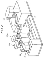
- Figure 4 shows a conventional polishing apparatus comprising: a
polishing unit 10; a loading/unloading unit 21; atransfer robot 22, and twocleaning machines polishing unit 10 comprising aturntable 12 having apolishing cloth 11 attached thereto; and atop ring 13 for holding aworkpiece 1 and pressing the workpiece (wafer) 1 onto theturntable 12. - Polishing is carried out by holding a
workpiece 1 at the bottom surface of thetop ring 13, and pressing theworkpiece 1 by means of a vertically movable cylinder onto the polishingcloth 11 mounted on the top surface of the rotatingturntable 12. In the meantime, a polishing solution Q is supplied from adelivery nozzle 14 in such a way to retain the solution Q between the bottom surface of theworkpiece 1 and the abrading surface of thepolishing cloth 11. - The
turntable 12 and thetop ring 13 are rotated independently at their individual controlled speed. As shown in Figure 6, thetop ring 13 is positioned in relation to theturntable 12, so that the peripheral edge of theworkpiece 1 is located at distances "a" and "b", respectively, from the center and the peripheral edge of theturntable 12 so that the entire surface of theworkpiece 1 can be polished uniformly at some high rotational speeds. It indicates that the diameter "D" of theturntable 12 is chosen according to the following relation to be more than twice the diameter d of the workpiece 1:
- The polished
workpiece 1 is processed in thecleaning machines unloading unit 21 to be stored in aportable workpiece cassette 24. A scrub washing is used which involves the use of brushes made of nylon or mohair, or a sponge made from polyvinylalcohol (PVA). - The conventional polishing apparatus of the type described above is satisfactory from the standpoint of achieving adequate flatness and efficiency owing to large relative displacements between the
turntable 12 and thetop ring 13 as well as their high relative speeds; however, surface roughness of the polished workpiece tends to be higher than desirable. To produce a polished workpiece of better surface quality, consideration may be given to using two turntables which are operated by varying the abrading qualities of the polishing cloths, rotational speeds and types of polishing solutions. However, as mentioned above, the diameter of the turntable is larger than twice that of the workpiece diameter, and each apparatus takes up a large floor space area which leads to higher facility costs. These problems becomes more ignorable as the industry seeks larger diameter substrates. - While it is possible to use one turntable to produce a superior surface quality by varying the type of polishing solution and lowering the rotational speed, for example, it is obvious that such an approach leads not only to a potential increase in the cost of polishing solution but to inevitable lowering in the production efficiency due to a prolonged operation.
- The conventional method also has some problems in the cleaning process when scrubbing follows the use of abrasive particles, not only because of the inherent difficulties of removing small particles in submicron ranges but also because of the ineffective cleaning when there is a strong affinity between the workpiece and the particles.
- Therefore, there has long been a need in the semiconductor device manufacturing industry for an efficient polishing method and facility which would enable to produce substrates of high surface qualities, such as flatness, smoothness and cleanliness, in a compact and low cost apparatus.
- It is an object of the present invention to provide a method for producing a high quality substrate having a high degree of flatness, smoothness and cleanliness, and to present a compact and efficient polishing apparatus including a polishing apparatus designed especially for the method.
- The object has been achieved in a method for polishing a workpiece comprising: a first step for polishing a work surface of the workpiece by pressing the work surface against an abrading surface of a first polishing tool which is being rotated; and a second step for processing the work surface by pressing the work surface against a rubbing surface of a second polishing tool which is being moved in a planar translation motion relatively to the work surface.
- In the above method, the planar translation motion includes a relative motion of two surfaces of many patterns. The typical pattern is circulative, i.e., repeating itself, and has a circular trace without respective rotation motion. However, it may include a respective rotation of a relatively large period of rotation compared to that of the circulative translation between the two surfaces. The trace of translation motion can be a linear translation pattern, a polygonal pattern or an elliptical pattern, but from the practical standpoint of polishing efficiency and mechanical ease, a circular pattern would be optimum. In the circulative translation motion, all the regions of the workpiece is subjected to a same pattern.
- In the present method, a high removal ratio and a high flatness of the workpiece such as a semiconductor wafer is achieved in the first step, by subjecting the workpiece to a highspeed material removal process with the first polishing tool. In the second step, a less aggressive polishing tool is used and the surface processing is carried out at a slower speed to attain a smooth surface on the workpiece, and also any micro-particles which may be adhered to the workpiece are removed. The surface of the workpiece is treated with a solution appropriate to the application; i.e., in the first step, abrasive particles are used while in the second step, purified water or a suitable chemical solution is used. In the second step, abrasive particles are normally not used, and if they are used, a small amount of ultra-fine particles are used, and the pressing pressure is reduced relative to the first step.
- An aspect of the method is that in the second step, at least one of the workpiece and the polishing tool is rotated with a period of rotation significantly in excess of a period of the circulative translation motion. Accordingly, the location of contact between the surface to be polished and the rubbing surface is gradually changed so as to lead to an overall uniform polishing of the workpiece.
- Another aspect of the method is that, in the second step, purified water is used as a polishing solution. Accordingly, this is the last step before the workpiece is subjected to other device manufacturing steps, so that the cleaning step assures that the micro-particles are thoroughly removed from the workpiece.
- The object is achieved in a polishing apparatus designed for the method presented above comprising: a first polishing section having a first polishing tool, the first polishing tool having an abrading surface and being rotatable along the abrading surface, and a pressing device for forcing a work surface of a workpiece against the abrading surface; and a second polishing section having a second polishing tool and a pressing device for forcing the work surface against a rubbing surface of the second polishing tool, the second polishing tool being movable in a planar translation motion relative to the work surface.
- According to the apparatus, the second polishing tool is not designed to polish by an rotation motion thereof, but the work surface and the rubbing surface are made to undergo an overall translation motion so as not to provide any stationary contact point between the two surfaces. Using this design, the size of the second polishing unit can be only as large as a sum of the base area plus the area of translation motion, thereby presenting a compact polishing unit. The result is that a small drive motor is sufficient, and the floor space required can also be reduced. These advantages become more important as the size of the workpiece to be polished increases. Further, because the second polishing unit does not need to rotate, relative polishing speed in all regions of the workpiece is the same, and flatness can readily be produced, and smoothness can be achieved relatively quickly.
- In another aspect of the invention, a polishing apparatus comprises: a support base; a support section for supporting the second polishing tool so as to enable a circulative translation motion; and a driving device to enable the support section to maintain the circulative translation motion.
- The support section may comprise a surface plate having a tool attachment surface. The support section may support the surface plate at not less than three locations around a periphery of the surface plate, so that the workpiece can be supported stably under a pressing pressure so as to improve the flatness of the workpiece.
- Another aspect of the apparatus presented above is that the support section comprises a connecting member having a pair of shafts, each having an axis which is displaced from each other, so as to enable each shaft to be located in a respective cavity formed on the surface plate and on the support base. Accordingly, a simple coupling is sufficient to produce effective polishing action.
- Another aspect of the apparatus presented above is that the surface plate includes a polishing solution supply passage opening at the top surface. Accordingly, every region of the workpiece, including the central region, can be supplied with the polishing solution to effect efficient polishing.
- Another aspect of the apparatuses presented above is that the driving device comprises a driving end member having an axis displaced with respect to a rotational axis of a drive source of the driving device and the surface plate comprises a cavity for operatively coupling with the driving end member. Accordingly, the translation motion can be achieved through a simple coupling arrangement.
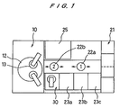
- Figure 1 is an overall plan view of the arrangement of the polishing apparatus of the present invention.
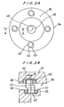
- Figure 2 is a cross sectional view of a finish polishing unit.
- Figure 3A is a plan view of the surface plate shown in Figure 2 looking towards the drive motor of the polishing apparatus.
- Figure 3B is a cross sectional view of the surface plate shown in Figure 2.
- Figure 4 is a perspective view of a conventional polishing apparatus.
- Figure 5 is a cross sectional view of another embodiment of the finish polishing unit.
- Figure 6 is a cross sectional view of a conventional polishing unit.
- Figure 1 shows an embodiment of the arrangement of the component units in the polishing apparatus of the present invention. At one end of a rectangular shaped floor space, there is a loading/unloading
unit 21 for delivery of workpieces which are to be polished or already polished. At the opposite end of the floor space, there is a main polishing unit (a first polishing section) 10 having a turntable and a top ring. These twounits robotic transport devices main polishing unit 10, there is aworkpiece inverter 25 for turning over a workpiece, and on the opposite lateral side, there are disposed a finish polishing unit (a second polishing section) 30 and threecleaning machines main polishing unit 10 is provided with oneturntable 12 and twotop rings 13, and is capable of parallel processing of two workpieces, but other features are the same as those in the conventional polishing apparatus referred to in Figures 4, 5. - The construction of the
finish polishing unit 30 will be described with reference to Figures 2, 3. Thefinish polishing unit 30 comprises atranslation table section 31 which provides a circulative translation motion of the abrading surface of the polishing tool, and atop ring 32 for holding theworkpiece 1 to direct its surface to be polished downwards and pressing theworkpiece 1 onto the abrading surface with a given pressure. - The
translation table section 31 comprises: acylindrical casing 34 housing amotor 33 therein; an annularoverhang plate section 35 protruding inwards at an upper portion of thecylindrical casing 34; threesupport sections 36 formed around the circumference of theoverhang plate section 35; and asurface plate 37 supported on thesupport sections 36 and mounted with a polishing cloth (polishing tool) 59 attached thereon. As shown in Figure 3B, the upper surface of theoverhang plate section 35 and the bottom surface of thesurface plate 37 respectively include a plurality ofcavity sections corresponding bearings bearings lower shafts members 44. The center of theupper shaft 42 of each connectingmembers 44 is displaced from the center of thelower shaft 43 by an eccentricity distance "e", as shown in Figure 3, thereby permitting thesurface plate 37 to undergo a circulative translation motion over a distance of radius "e". - A
cavity section 48 is provided in the central region of the bottom surface of thesurface plate 37 for housing a drive bearing 47 for supporting thedrive end 46 which is formed at a top surface of themain shaft 45 of thedrive motor 33, whose axis Z2 is displaced with respect to the axis Z1 of themain shaft 45. The amount of offset is also "e". Thedrive motor 33 is housed in themotor chamber 49 provided in thecasing 34, and itsmain shaft 45 is supported by the top andbottom bearings balancers - The radius of the
surface plate 37 is chosen to exceed the sum of the offset radius "e" plus the radius of the workpiece to be polished, and is constructed by overlaying two pieces ofdisc members fluid passage 55 for carrying the polishing solution is formed between the overlaid twodiscs surface plate 37 as well as with a plurality of polishingsolution supply openings 57 opening at the upper surface of thedisc 53. The polishingcloth 59 which is attached to the top surface of thesurface plate 37 is also provided with a plurality ofholes 58 to correspond with the polishingsolution supply openings 57. The holes are generally uniformly distributed across the entire surface of thesurface plate 37. It is feasible to provide a series of fluid flow grooves on the polishingcloth 59 in a pattern of lattices, spirals or radials which are communicated with thesolution supply openings 58. - The
top ring 32 serves as a pressing device for theworkpiece 1 onto the translation table 31 and is attached to the bottom of ashaft 60 so as to permit a free tilting within a certain degree by way of a joint. The compression force exerted by an unshown air cylinder as well as the rotational force exerted by a motor are transmitted to thetop ring 32 through theshaft 60. Thetop ring 32 is constructed similarly to those shown in Figures 4, 5, except that thistop ring 32 rotates at a slower speed. On the outer top side of thecasing 34, there is asolution collection tank 61 to collect the polishing solution supplied. - The operation of the polishing apparatus presented above will be described hereinafter. The
workpieces 1 in the workpiece storage cassette 24 (see Figure 4) are attached to each of the top rings 13 of themain polishing unit 10 by thetransport robots inverter 25 when necessary. As shown in Figure 6, thetop ring 13 rotates while pressing on theworkpiece 1 onto the polishingcloth 11 mounted on theturntable 12. A first step polishing is carried out by the actions of the highspeed relative movement between theworkpiece 1 and the polishingcloth 11, and of the chemical effects produced by the polishing solution Q supplied from thedelivery nozzle 14. - The
workpiece 1 which has completed the first polishing step is, either directly or after a rough cleaning step, transferred to thefinish polishing unit 30 to be subjected to the second polishing step. Here, thesurface plate 37 undergoes a circulative translation motion, and theworkpiece 1 held by thetop ring 32 is pressed onto the rubbing surface of the polishingcloth 59 attached to thesurface plate 37. - Finish polishing is provided by using the polishing solution Q supplied through the polishing
solution supply openings 56,fluid passages 55 and through thesolution supply openings workpiece 1 being polished. The action of the minute circulative translation motion of radius "e" between theworkpiece 1 and the rubbing surface of the polishingcloth 59 produces a uniform polish on the entire surface to be polished of theworkpiece 1. - When the
workpiece 1 is processed by the polishingcloth 59 in a same relative positioning to each other, it causes some problems introduced by local differences in the surface conditions of the polishingcloth 59, and to avoid such problems, thetop ring 32 is rotated slowly so as to cancel the local difference effect. - In the first polishing step, the
workpiece 1 and the polishingcloth 11 are moved in relation to each other at high speeds under a relative high pressing force so as to produce a certain amount of workpiece material removal. In the second polishing step, the purpose is to improve the surface flatness and smoothness as well as to remove micro-particles adhering to theworkpiece 1, and to this end, the roughness of the polishingcloth 59 is reduced, and the speed of relative movement and pressing force are also reduced compared with those in the first polishing step. Also, the polishing in the second polishing step is normally carried out using purified water, and chemicals and special slurries are used only when it is necessary. - The
workpiece 1, which has been processed through the second polishing step, is subjected to several cleaning steps, as necessary, in thecleaning machines 23a∼23c, and is stored in theworkpiece cassette 24. In this embodiment of the polishing apparatus, since twotop rings 13 are provided on themain polishing unit 10, by setting the polishing duration in the second polishing step to be one half of that in the first polishing operation, each apparatus can be operated without loss time thereby at its optimum processing efficiency. - In this polishing apparatus, since the polishing process is carried out in two stages which are being carried out simultaneously, the time duration in the first polishing step can be reduced, so that the process throughput is increased compared to the rate achievable with the conventional polishing apparatus shown in Figures 4, 5. Also, because the
finish polishing unit 30 is a circulative translation type, the size of thesurface plate 37 only needs to be larger than the size of theworkpiece 1 by the amount of the twice of offset "e". Therefore, compared with a polishing apparatus having two turntables of the same size as themain polishing unit 10, the required floor space is reduced significantly. Further, because thefinish polishing unit 30 is based on circulative translation motion, it is possible to design the support structure at several locations along the peripheral edges of thesurface plate 37, as shown in Figure 2, so that the improved flatness is achievable due to the stable supporting mechanism of thesurface plate 37 compared with high rotational speed turntables. - In the following, some of the typical operating parameters in the first and second polishing steps are compared.
-
- Polishing solution
- depends on material to be polished
- Polishing cloth
- depends on material to be polished
- Pressing pressure
- 200∼500 g/cm2
- Relative speed
- 0.07∼0.6 m/sec
- Polishing duration
- depends on material removal requirement
-
- Polishing solution
- water, chemicals, or slurry
- Polishing cloth
- soft cloth (non woven fabric, laminated nap)
- Pressing pressure
- 0∼200 g/cm2
- Relative speed
- 0.07∼0.6 m/sec
- Polishing duration
- 10∼120 sec
- In the above embodiment of the
finish polishing unit 30, the polishingtool 59 is made to undergo a circulative translation motion but it is also permissible to arrange so that thetop ring 32 for holding the workpiece is made to undergo the same motion while the polishingtool 59 is kept stationary. Also, crank type of connectingmembers 44 were used in thesupport sections 36 to connect to the surface plate, but it is permissible to use other types of support systems such as magnetic bearings and dry roller bearings, so long as they can provide translation movement of thesurface plate 37 while inhibiting its free-rotation. - Also, in this embodiment, the circulative translation motion was produced by an "eccentric" design provided at the end of the drive shaft of the motor, but other designs, for example, such as a so-called "X-Y stage" movable in the X- and Y-directions may be utilized to produce a translation motion of a similar trace as a vector sum for the
surface plate 37. - Figure 5 shows an embodiment of a polishing apparatus of this type comprising a
top ring 100 for mounting a workpiece on the lower surface thereof, and apolishing tool 101 arranged beneath thetop ring 100 and attached to the X-Y stage. In this embodiment, an electro plated grindstone is utilized as a polishing tool of a relatively small abrasive grain size. The X-Y stage comprises an X-stage 102, a Y-stage 103 and a fixingplate 104 which are overlaid in the order and mounted on abase 105. Between the X-stage 102 and the Y-stage 103 are provided a linear guide mechanism and a linear driving mechanism such as a feed screw so as to make the X-stage 102 movable in the X direction. The same mechanisms are provided between the Y-stage 103 and the fixingplate 104, and a controller device is provided for controlling these X- and Y- direction driving mechanism. - In the present embodiment, by applying a displacement having a sine- and a cosine-wave of a same phase to the X-stage 102 and the Y-
stage 103 respectively, the X-stage 102 will conduct a circular translation motion as a sum vector of both direction movements. Thus, thepolishing tool 101 undergoes a circulative translation motion as in the first embodiment of the invention. It is preferable to rotate thetop ring 100 with a period of rotation significantly in excess of a period of the circulative translation motion of thetool 101 in order to eliminate the effect resulting from a local difference of surface condition of the tool. - This embodiment, since a mechanical "eccentric" design is not used, has an advantage of having more degrees of freedom in changing the trace of the circulative translation motion. For example, since it is possible to change the diameter of the circular translation motion without stopping the operation, the polishing motion during the polishing step of a workpiece can be changed so as to polish with a smaller diameter in the starting and ending period than in the usual polishing period. By applying such a control method, it can avoid the deteriorative effects caused by the localized condition differences on the polishing tool surface, such as a unidirectional scar, when repeating a simple circulative motion.
- This embodiment can create not only a circular motion but also any other type of circulative translation motion such as, an ellipsoidal motion, an eight-shape (8) motion or an oscillating spiral motion, or any kind of combination thereof. Further, this embodiment can create not only a circulative motion having a certain trace but also a totally random translation motion which is by no means circulative. This intentional randomization of the relative translation motion can be performed by using a random number generation function of a computer processor, for example. In this case, it is preferable to retain a minimum radius of curvature of the trace in order to keep a smooth motion.
- It has thus been demonstrated in the present method that by dividing the polishing process into two stages, first and second polishing steps, it is possible to produce a high degree of flatness and smoothness on workpiece. In the first polishing step, the workpiece and the polishing tool are moved relative to each other at relatively high speeds to produce flatness on the workpiece. This is followed by a second step to obtain smooth surface on the workpiece by using a polishing tool having a lesser abrasive quality and providing a relatively small degree of relative motion between the workpiece and the polishing tool. The polishing process is completed by removing micro-particles which may be adhering to the workpiece, to produce a workpiece having a high degree of flatness, smoothness and cleanliness.
- It has also be demonstrated that, since the second polishing unit of the present invention undergoes a circulative translation motion, the size of the apparatus can be small enough to be slightly larger than the workpiece by the distance of eccentricity to enable a compact apparatus to be presented. Additional benefit is that the drive motor can be small and the occupied floor space is also small. The surface plate is supported at more than three locations around the periphery of the surface plate so that the application of the pressing force does not affect the stability of supporting member and the flatness of the polished surface can be maintained.
- It should be noted that the objects and advantages of the invention may be attained by means of any compatible combination(s) particularly pointed out in the items of the following summary of the invention and the appended claims.
- 1. A method for polishing a workpiece comprising:
- a first step for polishing a work surface of said workpiece by pressing said work surface against an abrading surface of a first polishing tool which is being rotated; and
- a second step for processing said work surface by pressing said work surface against a rubbing surface of a second polishing tool which is being moved in a planar translation motion relatively to said work surface.
- 2. A polishing method , wherein, in said second step, said relative translation motion is a circulative motion having a certain pattern.
- 3. A polishing method , wherein, in said second step, said relative translation motion is provided by moving said second polishing tool.
- 4. A polishing method , wherein, in said second step, said relative translation motion is a random motion.
- 5. A polishing method , wherein, in said second step, said random relative translation motion is provided as a sum vector of at least two linear motion.
- 6. A polishing method , wherein the pressing pressure for pressing said work surface against an abrading surface of said first polishing tool is 200∼500 g/cm2 and the pressing pressure for pressing said work surface against an rubbing surface of said second polishing tool is 0∼200 g/cm2.
- 7. A polishing method , wherein, in said second step, at least one of said workpiece and said polishing tool is rotated with a period of rotation significantly in excess of a period of said circulative translation motion.
- 8. A polishing method , wherein, in said second step, purified water is used as a polishing solution.
- 9. A polishing apparatus comprising:
- a first polishing section having a first polishing tool, said first polishing tool having an abrading surface and being rotatable along said abrading surface, and a pressing device for forcing a work surface of a workpiece against said abrading surface; and
- a second polishing section having a second polishing tool and a pressing device for forcing said work surface against a rubbing surface of said second polishing tool, said second polishing tool being movable in a planar translation motion relative to said work surface.
- 10. A polishing apparatus , wherein said second polishing section comprises: a support section for supporting said second polishing tool so as to enable a circulative translation motion; and a driving device to enable said support section to maintain said circulative translation motion.
- 11. A polishing apparatus , wherein said driving device comprises a driving end member having an axis displaced with respect to a rotational axis of a drive source of said driving device and said support section comprises a cavity for operatively coupling with said driving end member.
- 12. A polishing apparatus , wherein the pressing pressure for pressing said work surface against an abrading surface of said first polishing tool is 200∼500 g/cm2 and the pressing pressure for pressing said work surface against an rubbing surface of said second polishing tool is 0∼200 g/cm2.
- 13. A polishing apparatus comprising: a support base; a surface plate having a top surface for attaching a polishing tool; a support section for supporting said surface plate so as to enable a circulative translation motion; and a driving device to enable said surface plate to maintain said circulative translation motion.
- 14. A polishing apparatus , wherein said support section supports said surface plate at not less than three locations around a periphery of said surface plate.
- 15. A polishing apparatus , wherein said support section comprises a connecting member having a pair of shafts, each having an axis which is displaced from each other, so as to enable each shaft to be located in a respective cavity formed on said surface plate and on said support base.
- 16. A polishing apparatus , wherein said surface plate includes a polishing solution supply passage opening at said top surface.
- 17. A polishing apparatus , wherein said driving device comprises a driving end member having an axis displaced with respect to a rotational axis of a drive source of said driving device and said surface plate comprises a cavity for operatively coupling with said driving end member.
- 18. A polishing apparatus comprising: a support base; a surface plate having a top surface for attaching a polishing tool; a first support section for supporting said surface plate so as to enable a linear translation motion in a first direction; a second support section for supporting said first support section so as to enable a linear translation motion in a second direction different to said first direction and driving means for driving said surface plate and said first and second support sections to maintain said linear translation motion.
- 19. A method for polishing a workpiece comprising:
- a first step for polishing a work surface of said workpiece by pressing said work surface against an abrading surface of a first polishing tool which is being rotated; and
- a second step for processing said work surface by pressing said work surface against a rubbing surface of a second polishing tool which is substantially being moved in a planar translation motion relative to said work surface.
- 20. A polishing method , wherein, said second polishing tool is moved substantially without relative rotation to said work surface.
- 21. A polishing apparatus comprising:
- a first polishing section having a first polishing tool, said first polishing tool having an abrading surface and being rotatable along said abrading surface, and a pressing device for forcing a work surface of a workpiece against said abrading surface; and
- a second polishing section having a second polishing tool and a pressing device for forcing said work surface against a rubbing surface of said second polishing tool, said second polishing tool being movable substantially in a planar translation motion relative to said work surface.
- 22. A polishing apparatus , wherein, said second polishing tool is moved substantially without relative rotation to said work surface.
Claims (13)
- A method for polishing a workpiece comprising:a first step for polishing a work surface of said workpiece by pressing said work surface against an abrading surface of a first polishing tool which is being rotated; anda second step for processing said work surface by pressing said work surface against a rubbing surface of a second polishing tool which is being moved in a planar translation motion relatively to said work surface.
- A polishing method according to claim 1, wherein, in said second step, said relative translation motion is a circulative motion having a certain pattern, and/or wherein preferably , in said second step, said relative translation motion is provided by moving said second polishing tool.
- A polishing method according to claim 1, wherein, in said second step, said relative translation motion is a random motion. , in said second step, said random relative translation motion is provided as a sum vector of at least two linear motion.
- A polishing method according to claim 1, wherein the pressing pressure for pressing said work surface against an abrading surface of said first polishing tool is 200∼500 g/cm2 and the pressing pressure for pressing said work surface against an rubbing surface of said second polishing tool is 0∼200 g/cm2.
- A polishing method according to claim 2, wherein, in said second step, at least one of said workpiece and said polishing tool is rotated with a period of rotation significantly in excess of a period of said circulative translation motion.
- A polishing method according to claim 1, wherein, in said second step, purified water is used as a polishing solution.
- A polishing apparatus comprising:a first polishing section having a first polishing tool, said first polishing tool having an abrading surface and being rotatable along said abrading surface, and a pressing device for forcing a work surface of a workpiece against said abrading surface; anda second polishing section having a second polishing tool and a pressing device for forcing said work surface against a rubbing surface of said second polishing tool, said second polishing tool being movable in a planar translation motion relative to said work surface.
- A polishing apparatus according to claim 7, wherein said second polishing section comprises: a support section for supporting said second polishing tool so as to enable a circulative translation motion; and a driving device to enable said support section to maintain said circulative translation motion, and/or wherein preferably said driving device comprises a driving end member having an axis displaced with respect to a rotational axis of a drive source of said driving device and said support section comprises a cavity for operatively coupling with said driving end member, and/or wherein preferably the pressing pressure for pressing said work surface against an abrading surface of said first polishing tool is 200∼500 g/cm2 and the pressing pressure for pressing said work surface against an rubbing surface of said second polishing tool is 0∼200 g/cm2.
- A polishing apparatus comprising: a support base; a surface plate having a top surface for attaching a polishing tool; a support section for supporting said surface plate so as to enable a circulative translation motion; and a driving device to enable said surface plate to maintain said circulative translation motion.
- A polishing apparatus according to claim 13, wherein said support section supports said surface plate at not less than three locations around a periphery of said surface plate, and/or wherein preferably said support section comprises a connecting member having a pair of shafts, each having an axis which is displaced from each other, so as to enable each shaft to be located in a respective cavity formed on said surface plate and on said support base, and/or wherein preferably said surface plate includes a polishing solution supply passage opening at said top surface, and/or wherein preferably said driving device comprises a driving end member having an axis displaced with respect to a rotational axis of a drive source of said driving device and said surface plate comprises a cavity for operatively coupling with said driving end member.
- A polishing apparatus comprising: a support base; a surface plate having a top surface for attaching a polishing tool; a first support section for supporting said surface plate so as to enable a linear translation motion in a first direction; a second support section for supporting said first support section so as to enable a linear translation motion in a second direction different to said first direction and driving means for driving said surface plate and said first and second support sections to maintain said linear translation motion.
- A method for polishing a workpiece comprising:a first step for polishing a work surface of said workpiece by pressing said work surface against an abrading surface of a first polishing tool which is being rotated; anda second step for processing said work surface by pressing said work surface against a rubbing surface of a second polishing tool which is substantially being moved in a planar translation motion relative to said work surface. and/or wherein preferably, said second polishing tool is moved substantially without relative rotation to said work surface.
- A polishing apparatus comprising:a first polishing section having a first polishing tool, said first polishing tool having an abrading surface and being rotatable along said abrading surface, and a pressing device for forcing a work surface of a workpiece against said abrading surface; anda second polishing section having a second polishing tool and a pressing device for forcing said work surface against a rubbing surface of said second polishing tool, said second polishing tool being movable substantially in a planar translation motion relative to said work surface, and/or wherein preferably, said second polishing tool is moved substantially without relative rotation to said work surface.
Priority Applications (1)
| Application Number | Priority Date | Filing Date | Title |
|---|---|---|---|
| EP02018968A EP1281476A3 (en) | 1996-05-16 | 1997-05-16 | Method for polishing workpieces and apparatus therefor |
Applications Claiming Priority (3)
| Application Number | Priority Date | Filing Date | Title |
|---|---|---|---|
| JP14677696 | 1996-05-16 | ||
| JP146776/96 | 1996-05-16 | ||
| JP14677696 | 1996-05-16 |
Related Child Applications (1)
| Application Number | Title | Priority Date | Filing Date |
|---|---|---|---|
| EP02018968A Division EP1281476A3 (en) | 1996-05-16 | 1997-05-16 | Method for polishing workpieces and apparatus therefor |
Publications (3)
| Publication Number | Publication Date |
|---|---|
| EP0807492A2 true EP0807492A2 (en) | 1997-11-19 |
| EP0807492A3 EP0807492A3 (en) | 1998-11-04 |
| EP0807492B1 EP0807492B1 (en) | 2003-03-19 |
Family
ID=15415286
Family Applications (2)
| Application Number | Title | Priority Date | Filing Date |
|---|---|---|---|
| EP97108027A Expired - Lifetime EP0807492B1 (en) | 1996-05-16 | 1997-05-16 | Method for polishing workpieces and apparatus therefor |
| EP02018968A Withdrawn EP1281476A3 (en) | 1996-05-16 | 1997-05-16 | Method for polishing workpieces and apparatus therefor |
Family Applications After (1)
| Application Number | Title | Priority Date | Filing Date |
|---|---|---|---|
| EP02018968A Withdrawn EP1281476A3 (en) | 1996-05-16 | 1997-05-16 | Method for polishing workpieces and apparatus therefor |
Country Status (3)
| Country | Link |
|---|---|
| US (1) | US5989107A (en) |
| EP (2) | EP0807492B1 (en) |
| DE (1) | DE69719847T2 (en) |
Cited By (16)
| Publication number | Priority date | Publication date | Assignee | Title |
|---|---|---|---|---|
| EP0842738A3 (en) * | 1996-11-15 | 1998-12-09 | Ebara Corporation | Method of and apparatus for polishing and cleaning planar workpiece |
| WO1999026761A1 (en) * | 1997-11-21 | 1999-06-03 | Ebara Corporation | Polishing apparatus |
| WO1999026763A3 (en) * | 1997-11-21 | 1999-09-02 | Ebara Corp | Polishing apparatus |
| EP1077108A1 (en) * | 1999-08-18 | 2001-02-21 | Ebara Corporation | Polishing method and polishing apparatus |
| US6213853B1 (en) | 1997-09-10 | 2001-04-10 | Speedfam-Ipec Corporation | Integral machine for polishing, cleaning, rinsing and drying workpieces |
| US6309279B1 (en) | 1999-02-19 | 2001-10-30 | Speedfam-Ipec Corporation | Arrangements for wafer polishing |
| US6343978B1 (en) | 1997-05-16 | 2002-02-05 | Ebara Corporation | Method and apparatus for polishing workpiece |
| US6354922B1 (en) | 1999-08-20 | 2002-03-12 | Ebara Corporation | Polishing apparatus |
| US6413156B1 (en) | 1996-05-16 | 2002-07-02 | Ebara Corporation | Method and apparatus for polishing workpiece |
| EP1050369A3 (en) * | 1999-04-29 | 2003-01-22 | Ebara Corporation | Method and apparatus for polishing workpieces |
| US6555466B1 (en) | 1999-03-29 | 2003-04-29 | Speedfam Corporation | Two-step chemical-mechanical planarization for damascene structures on semiconductor wafers |
| EP1034887A3 (en) * | 1999-03-05 | 2003-07-16 | Ebara Corporation | Polishing apparatus |
| US6595831B1 (en) | 1996-05-16 | 2003-07-22 | Ebara Corporation | Method for polishing workpieces using fixed abrasives |
| US6682408B2 (en) | 1999-03-05 | 2004-01-27 | Ebara Corporation | Polishing apparatus |
| SG119138A1 (en) * | 1998-04-28 | 2006-02-28 | Ebara Corp | Abrading plate and polishing method using the same |
| CN103223638A (en) * | 2013-04-28 | 2013-07-31 | 上海华力微电子有限公司 | Chemical machinery polishing device |
Families Citing this family (14)
| Publication number | Priority date | Publication date | Assignee | Title |
|---|---|---|---|---|
| US6116994A (en) * | 1997-04-11 | 2000-09-12 | Ebara Corporation | Polishing apparatus |
| TW375556B (en) * | 1997-07-02 | 1999-12-01 | Matsushita Electric Industrial Co Ltd | Method of polishing the wafer and finishing the polishing pad |
| US6184139B1 (en) | 1998-09-17 | 2001-02-06 | Speedfam-Ipec Corporation | Oscillating orbital polisher and method |
| WO2000024548A1 (en) * | 1998-10-28 | 2000-05-04 | Hitachi, Ltd. | Polishing apparatus and a semiconductor manufacturing method using the same |
| JP3979750B2 (en) * | 1998-11-06 | 2007-09-19 | 株式会社荏原製作所 | Substrate polishing equipment |
| JP3797822B2 (en) * | 1999-06-30 | 2006-07-19 | 株式会社荏原製作所 | Polishing device |
| JP2001038615A (en) * | 1999-07-26 | 2001-02-13 | Ebara Corp | Polishing device |
| US6712678B1 (en) * | 1999-12-07 | 2004-03-30 | Ebara Corporation | Polishing-product discharging device and polishing device |
| JP2002043474A (en) * | 2000-07-21 | 2002-02-08 | Nakamura Seisakusho Kk | Method of forming electronic component package |
| US6887136B2 (en) * | 2001-05-09 | 2005-05-03 | Applied Materials, Inc. | Apparatus and methods for multi-step chemical mechanical polishing |
| US6641462B2 (en) * | 2001-06-27 | 2003-11-04 | Speedfam-Ipec Corporation | Method and apparatus for distributing fluid to a polishing surface during chemical mechanical polishing |
| DE102006031098A1 (en) * | 2006-07-05 | 2008-01-10 | GM Global Technology Operations, Inc., Detroit | Vehicle-sided device for assembly of e.g. clamping belt, has brackets with recesses or projections for accommodating fastening unit or accommodation units, where brackets are directly connected, welded or bolted with substructure of vehicle |
| JP5526895B2 (en) * | 2009-04-01 | 2014-06-18 | 信越化学工業株式会社 | Manufacturing method of large synthetic quartz glass substrate |
| DE112015002319B4 (en) | 2014-12-31 | 2024-07-25 | Osaka University | Planarization machining method and planarization machining apparatus |
Family Cites Families (21)
| Publication number | Priority date | Publication date | Assignee | Title |
|---|---|---|---|---|
| DE197634C (en) * | ||||
| US3659386A (en) * | 1968-03-22 | 1972-05-02 | Ibm | A method for providing a finished surface on workpieces |
| US3638933A (en) * | 1970-08-10 | 1972-02-01 | Yosemite Lab | Precision x-y positioning table |
| JPS55134414A (en) * | 1979-04-06 | 1980-10-20 | Hitachi Ltd | Precise moving unit |
| CH668574A5 (en) * | 1985-05-23 | 1989-01-13 | Exnii Metallorezh Stankov | NC VERTICAL GRINDING MACHINE. |
| US4680893A (en) * | 1985-09-23 | 1987-07-21 | Motorola, Inc. | Apparatus for polishing semiconductor wafers |
| KR0129662B1 (en) * | 1987-10-30 | 1998-04-07 | 고다까 토시오 | Moving table apparatus |
| US5083401A (en) * | 1988-08-08 | 1992-01-28 | Mitsubishi Denki Kabushiki Kaisha | Method of polishing |
| JPH02208931A (en) * | 1989-02-08 | 1990-08-20 | Hitachi Cable Ltd | Polishing process for compound semiconductor substrate |
| US5228177A (en) * | 1990-03-03 | 1993-07-20 | Herzog Maschinenfabrik Gmbh & Co. | Sample preparation system for iron and steel samples |
| US5184433A (en) * | 1990-03-16 | 1993-02-09 | Aster Corporation | Fiber optic polisher |
| JPH0469147A (en) * | 1990-07-11 | 1992-03-04 | Mabuchi Shoten:Kk | Relatively equal speed polishing method |
| EP0517594B1 (en) * | 1991-06-06 | 1995-12-13 | Commissariat A L'energie Atomique | Polishing machine with a tensioned finishing belt and an improved work supporting head |
| JP3233664B2 (en) * | 1991-09-13 | 2001-11-26 | 土肥 俊郎 | Method and apparatus for planarization polishing of wafer with device |
| US5232875A (en) * | 1992-10-15 | 1993-08-03 | Micron Technology, Inc. | Method and apparatus for improving planarity of chemical-mechanical planarization operations |
| US5554064A (en) * | 1993-08-06 | 1996-09-10 | Intel Corporation | Orbital motion chemical-mechanical polishing apparatus and method of fabrication |
| JPH07285069A (en) * | 1994-04-18 | 1995-10-31 | Shin Etsu Handotai Co Ltd | Automatic taper removal polishing method and device of wafer in sheet type polishing |
| US5571373A (en) * | 1994-05-18 | 1996-11-05 | Memc Electronic Materials, Inc. | Method of rough polishing semiconductor wafers to reduce surface roughness |
| US5503589A (en) * | 1994-06-17 | 1996-04-02 | Wikle; Kenneth C. | Apparatus and method for contour grinding gas turbine blades |
| US5551986A (en) * | 1995-02-15 | 1996-09-03 | Taxas Instruments Incorporated | Mechanical scrubbing for particle removal |
| US5908530A (en) * | 1995-05-18 | 1999-06-01 | Obsidian, Inc. | Apparatus for chemical mechanical polishing |
-
1997
- 1997-05-16 EP EP97108027A patent/EP0807492B1/en not_active Expired - Lifetime
- 1997-05-16 US US08/857,252 patent/US5989107A/en not_active Expired - Lifetime
- 1997-05-16 EP EP02018968A patent/EP1281476A3/en not_active Withdrawn
- 1997-05-16 DE DE69719847T patent/DE69719847T2/en not_active Expired - Lifetime
Cited By (31)
| Publication number | Priority date | Publication date | Assignee | Title |
|---|---|---|---|---|
| US7011569B2 (en) | 1996-05-16 | 2006-03-14 | Ebara Corporation | Method and apparatus for polishing workpiece |
| US6595831B1 (en) | 1996-05-16 | 2003-07-22 | Ebara Corporation | Method for polishing workpieces using fixed abrasives |
| US6413156B1 (en) | 1996-05-16 | 2002-07-02 | Ebara Corporation | Method and apparatus for polishing workpiece |
| EP0842738A3 (en) * | 1996-11-15 | 1998-12-09 | Ebara Corporation | Method of and apparatus for polishing and cleaning planar workpiece |
| US6343978B1 (en) | 1997-05-16 | 2002-02-05 | Ebara Corporation | Method and apparatus for polishing workpiece |
| US6390897B1 (en) | 1997-09-10 | 2002-05-21 | Speedfam-Ipec Corporation | Cleaning station integral with polishing machine for semiconductor wafers |
| US6852007B1 (en) | 1997-09-10 | 2005-02-08 | Speedfam-Ipec Corporation | Robotic method of transferring workpieces to and from workstations |
| US6213853B1 (en) | 1997-09-10 | 2001-04-10 | Speedfam-Ipec Corporation | Integral machine for polishing, cleaning, rinsing and drying workpieces |
| US6227946B1 (en) | 1997-09-10 | 2001-05-08 | Speedfam-Ipec Corporation | Robot assisted method of polishing, cleaning and drying workpieces |
| US6520839B1 (en) | 1997-09-10 | 2003-02-18 | Speedfam-Ipec Corporation | Load and unload station for semiconductor wafers |
| US6350177B1 (en) | 1997-09-10 | 2002-02-26 | Speedfam-Ipec Corporation | Combined CMP and wafer cleaning apparatus and associated methods |
| US6364745B1 (en) | 1997-09-10 | 2002-04-02 | Speedfam-Ipec Corporation | Mapping system for semiconductor wafer cassettes |
| US6332826B1 (en) | 1997-11-21 | 2001-12-25 | Ebara Corporation | Polishing apparatus |
| US6413146B1 (en) | 1997-11-21 | 2002-07-02 | Ebara Corporation | Polishing apparatus |
| US7101255B2 (en) | 1997-11-21 | 2006-09-05 | Ebara Corporation | Polishing apparatus |
| WO1999026761A1 (en) * | 1997-11-21 | 1999-06-03 | Ebara Corporation | Polishing apparatus |
| US6918814B2 (en) | 1997-11-21 | 2005-07-19 | Ebara Corporation | Polishing apparatus |
| WO1999026763A3 (en) * | 1997-11-21 | 1999-09-02 | Ebara Corp | Polishing apparatus |
| SG119138A1 (en) * | 1998-04-28 | 2006-02-28 | Ebara Corp | Abrading plate and polishing method using the same |
| US6309279B1 (en) | 1999-02-19 | 2001-10-30 | Speedfam-Ipec Corporation | Arrangements for wafer polishing |
| US6682408B2 (en) | 1999-03-05 | 2004-01-27 | Ebara Corporation | Polishing apparatus |
| US6878044B2 (en) | 1999-03-05 | 2005-04-12 | Ebara Corporation | Polishing apparatus |
| EP1034887A3 (en) * | 1999-03-05 | 2003-07-16 | Ebara Corporation | Polishing apparatus |
| US7632378B2 (en) | 1999-03-05 | 2009-12-15 | Ebara Corporation | Polishing apparatus |
| US6555466B1 (en) | 1999-03-29 | 2003-04-29 | Speedfam Corporation | Two-step chemical-mechanical planarization for damascene structures on semiconductor wafers |
| EP1050369A3 (en) * | 1999-04-29 | 2003-01-22 | Ebara Corporation | Method and apparatus for polishing workpieces |
| US6626739B1 (en) | 1999-08-18 | 2003-09-30 | Ebara Corporation | Polishing method and polishing apparatus |
| EP1077108A1 (en) * | 1999-08-18 | 2001-02-21 | Ebara Corporation | Polishing method and polishing apparatus |
| US6354922B1 (en) | 1999-08-20 | 2002-03-12 | Ebara Corporation | Polishing apparatus |
| CN103223638A (en) * | 2013-04-28 | 2013-07-31 | 上海华力微电子有限公司 | Chemical machinery polishing device |
| CN103223638B (en) * | 2013-04-28 | 2016-04-13 | 上海华力微电子有限公司 | Chemical-mechanical grinding device |
Also Published As
| Publication number | Publication date |
|---|---|
| EP1281476A2 (en) | 2003-02-05 |
| EP0807492B1 (en) | 2003-03-19 |
| US5989107A (en) | 1999-11-23 |
| DE69719847D1 (en) | 2003-04-24 |
| EP0807492A3 (en) | 1998-11-04 |
| DE69719847T2 (en) | 2004-02-05 |
| EP1281476A3 (en) | 2003-08-13 |
Similar Documents
| Publication | Publication Date | Title |
|---|---|---|
| EP0807492B1 (en) | Method for polishing workpieces and apparatus therefor | |
| US6413156B1 (en) | Method and apparatus for polishing workpiece | |
| US6343978B1 (en) | Method and apparatus for polishing workpiece | |
| US6413146B1 (en) | Polishing apparatus | |
| US6643882B1 (en) | Substrate cleaning apparatus | |
| KR102322525B1 (en) | Apparatus and method for processing a surface of a substrate | |
| US5860181A (en) | Method of and apparatus for cleaning workpiece | |
| US20020083577A1 (en) | Polishing member and apparatus | |
| US20020007840A1 (en) | Substrate cleaning apparatus, substrate cleaning method and substrate processing apparatus | |
| JP2004517479A (en) | System and method for polishing and planarizing a semiconductor wafer using a reduced surface area polishing pad and a variable partial pad-wafer overlap technique | |
| EP1121222A1 (en) | Oscillating orbital polisher and method | |
| EP0842738B1 (en) | Method of and apparatus for polishing and cleaning planar workpiece | |
| JPH1086058A (en) | Retention of polishing pad on platen in chemical mechanical polishing equipment | |
| KR100522888B1 (en) | An apparatus for polishing and a method therefor | |
| US6607427B2 (en) | Dressing apparatus and polishing apparatus | |
| KR100496916B1 (en) | Polishing method and apparatus of workpiece | |
| US12337439B2 (en) | Multiple disk pad conditioner | |
| JP2003225862A (en) | Polishing device | |
| US6116994A (en) | Polishing apparatus | |
| KR100219499B1 (en) | C.m.p. device and planarization method | |
| JP3998657B2 (en) | Substrate polishing method and apparatus | |
| RU2260872C2 (en) | Semiconductor wafer machine tool |
Legal Events
| Date | Code | Title | Description |
|---|---|---|---|
| PUAI | Public reference made under article 153(3) epc to a published international application that has entered the european phase |
Free format text: ORIGINAL CODE: 0009012 |
|
| AK | Designated contracting states |
Kind code of ref document: A2 Designated state(s): DE FR |
|
| PUAL | Search report despatched |
Free format text: ORIGINAL CODE: 0009013 |
|
| AK | Designated contracting states |
Kind code of ref document: A3 Designated state(s): DE FR |
|
| 17P | Request for examination filed |
Effective date: 19990420 |
|
| 17Q | First examination report despatched |
Effective date: 20001019 |
|
| GRAG | Despatch of communication of intention to grant |
Free format text: ORIGINAL CODE: EPIDOS AGRA |
|
| GRAG | Despatch of communication of intention to grant |
Free format text: ORIGINAL CODE: EPIDOS AGRA |
|
| GRAH | Despatch of communication of intention to grant a patent |
Free format text: ORIGINAL CODE: EPIDOS IGRA |
|
| GRAH | Despatch of communication of intention to grant a patent |
Free format text: ORIGINAL CODE: EPIDOS IGRA |
|
| GRAA | (expected) grant |
Free format text: ORIGINAL CODE: 0009210 |
|
| AK | Designated contracting states |
Designated state(s): DE FR |
|
| REF | Corresponds to: |
Ref document number: 69719847 Country of ref document: DE Date of ref document: 20030424 Kind code of ref document: P |
|
| ET | Fr: translation filed | ||
| PLBE | No opposition filed within time limit |
Free format text: ORIGINAL CODE: 0009261 |
|
| STAA | Information on the status of an ep patent application or granted ep patent |
Free format text: STATUS: NO OPPOSITION FILED WITHIN TIME LIMIT |
|
| 26N | No opposition filed |
Effective date: 20031222 |
|
| PGFP | Annual fee paid to national office [announced via postgrant information from national office to epo] |
Ref country code: FR Payment date: 20100525 Year of fee payment: 14 |
|
| PGFP | Annual fee paid to national office [announced via postgrant information from national office to epo] |
Ref country code: DE Payment date: 20100512 Year of fee payment: 14 |
|
| REG | Reference to a national code |
Ref country code: DE Ref legal event code: R119 Ref document number: 69719847 Country of ref document: DE |
|
| REG | Reference to a national code |
Ref country code: DE Ref legal event code: R119 Ref document number: 69719847 Country of ref document: DE |
|
| REG | Reference to a national code |
Ref country code: FR Ref legal event code: ST Effective date: 20120131 |
|
| PG25 | Lapsed in a contracting state [announced via postgrant information from national office to epo] |
Ref country code: FR Free format text: LAPSE BECAUSE OF NON-PAYMENT OF DUE FEES Effective date: 20110531 |
|
| PG25 | Lapsed in a contracting state [announced via postgrant information from national office to epo] |
Ref country code: DE Free format text: LAPSE BECAUSE OF NON-PAYMENT OF DUE FEES Effective date: 20111130 |