EP0807498A1 - Kettensägeschwert mit Identifizierungsmarkierungen - Google Patents
Kettensägeschwert mit Identifizierungsmarkierungen Download PDFInfo
- Publication number
- EP0807498A1 EP0807498A1 EP97303363A EP97303363A EP0807498A1 EP 0807498 A1 EP0807498 A1 EP 0807498A1 EP 97303363 A EP97303363 A EP 97303363A EP 97303363 A EP97303363 A EP 97303363A EP 0807498 A1 EP0807498 A1 EP 0807498A1
- Authority
- EP
- European Patent Office
- Prior art keywords
- guide bar
- chain
- insert
- bar
- saw
- Prior art date
- Legal status (The legal status is an assumption and is not a legal conclusion. Google has not performed a legal analysis and makes no representation as to the accuracy of the status listed.)
- Granted
Links
- 238000004519 manufacturing process Methods 0.000 claims description 2
- 239000000463 material Substances 0.000 description 6
- 238000010276 construction Methods 0.000 description 3
- 238000000034 method Methods 0.000 description 2
- 238000004806 packaging method and process Methods 0.000 description 2
- 239000003086 colorant Substances 0.000 description 1
- 238000005520 cutting process Methods 0.000 description 1
- 230000012447 hatching Effects 0.000 description 1
- 239000010687 lubricating oil Substances 0.000 description 1
- 238000003754 machining Methods 0.000 description 1
- 230000014759 maintenance of location Effects 0.000 description 1
- 230000013011 mating Effects 0.000 description 1
- 238000005259 measurement Methods 0.000 description 1
- 239000002184 metal Substances 0.000 description 1
- 238000012986 modification Methods 0.000 description 1
- 230000004048 modification Effects 0.000 description 1
- 239000007787 solid Substances 0.000 description 1
- 239000011343 solid material Substances 0.000 description 1
- 239000004575 stone Substances 0.000 description 1
- 238000009966 trimming Methods 0.000 description 1
- 230000000007 visual effect Effects 0.000 description 1
- 239000002023 wood Substances 0.000 description 1
Images
Classifications
-
- B—PERFORMING OPERATIONS; TRANSPORTING
- B27—WORKING OR PRESERVING WOOD OR SIMILAR MATERIAL; NAILING OR STAPLING MACHINES IN GENERAL
- B27B—SAWS FOR WOOD OR SIMILAR MATERIAL; COMPONENTS OR ACCESSORIES THEREFOR
- B27B17/00—Chain saws; Equipment therefor
- B27B17/02—Chain saws equipped with guide bar
- B27B17/025—Composite guide bars, e.g. laminated, multisectioned; Guide bars of diverse material
Definitions
- This invention relates to chain saws and more particularly it relates to guide bars with color coded indicia for mating guide bars to other chain saw components.
- Chain saws are popular and useful tools that are utilized by many industries and individual users. Probably the most common use of the chain saw is in cutting of wood products ranging from felling of trees, trimming branches from trees and sawing the logs resulting from the trees into lengths. Chain saws have also been applied to other industries such as the concrete or construction industry wherein the chain saw is utilized to saw such items as concrete and/or stone.
- the chain saw has a power head, a guide bar and an endless saw chain (a loop of chain).
- the guide bar is mounted to the power head and the endless chain is entrained around the guide bar with the chain having a drive link tang fitting in a groove of the guide bar.
- the saw chain is driven by a drive sprocket of the power head to propel the saw chain around the guide bar.
- saw chain there are many different types of saw chain having reference to the gauge of the chain (the width of the drive link tang which must be fit to the guide bar groove) and pitch (the distance between rivets which must be fit to a particular sprocket type, e.g., a nose sprocket provided on the nose end of the guide bar and the drive sprocket of the power head).
- gauge of the chain the width of the drive link tang which must be fit to the guide bar groove
- pitch the distance between rivets which must be fit to a particular sprocket type, e.g., a nose sprocket provided on the nose end of the guide bar and the drive sprocket of the power head.
- the guide bars, drive sprockets and saw chain are replaceable since they are subject to wear and/or damage when in use.
- New guide bars most often have details imprinted, painted, and/or stenciled on the side surfaces of the guide bar to enable a user to match the bar to a particular chain and/or sprocket.
- the guide bar when in use is generally subjected to a harsh environment.
- the guide bar of the chain saw will, for example, be traveling through the kerf produced by the saw chain and in the process the side surfaces of the guide bar will be rubbing against the material which is being sawn. Additionally, the guide bar is subjected to the lubricating oil which lubricates the guide bar and chain and will further be subjected to moisture, dirt and other items.
- the markings on the guide bar will over time through use of the guide bar generally be rubbed off or worn away.
- the guide bar or saw chain may appear to be the correct type however there are many different types of guide bars and saw chains that will appear similar to the untrained eye and the task of locating a desired replacement bar or chain can often be a frustrating experience particularly to a novice user.
- a chain saw with guide bar having identifying indicia comprising:
- a preferred embodiment of the guide bar of the present invention has a coloured insert as the identifying indicia that is fixedly mounted into an aperture of the guide bar.
- the coloured insert does not protrude from and is generally finished flush with the surface of the guide bar and therefore does not interfere with or affect the performance of the guide bar.
- the coloured insert has colour that extends below the exposes surface (or even throughout) so as to avoid it wearing off. The colour is accordingly readily discernable throughout the use of the guide bar.
- the insert may be further stamped with other identifying characters such as letters and numbers where simple colour does not provide the entire information required, e.g. to indicate bar mount design and/or chain loop length.
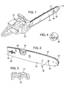
- Fig. 1 of the drawings which illustrates a chain saw 10.
- the chain saw 10 has a power head 12, a guide bar 16 and an endless chain 14.
- the guide bar 16 is mounted to the power head 12 and the saw chain 14 is entrained around the guide bar 16.
- the guide bar 16 has a guide groove 24 (Fig. 2) for receiving the saw chain 14.
- the chain 14 is driven by a drive sprocket of the power head 12 (not shown in the figure) and the saw chain 14 travels around the guide bar 16 as indicated by the directional arrow 18.
- the guide bar 16 and the saw chain 14 are removably mounted to the power head 12 and are replaceable units.
- Fig. 2 further illustrates the guide bar 16 and Fig. 3 illustrates a portion of the saw chain 14.
- the guide bar 16 is an elongate member that has a mounting tail 38 suited for mounting the guide bar 16 to the power head 12 of Fig. 1.
- the nose end of the bar is provided with a nose sprocket 42.
- the saw chain 14 is an articulated chain and has drive links 22 with depending tang portions that are received in a guide groove 24 of the guide bar 16.
- the drive links 22 will also be engaged by the drive sprocket of the power head 12 to propel the endless chain 14 around the guide bar 16 and they engage the sprocket teeth of sprocket 42 which supports the chain as it rounds the nose of the bar.
- the endless saw chain 14 must be of the proper loop length and of the proper gauge (the tangs of the drive links 22 having a width that fits groove 24) and pitch (the tangs being spaced to fit the sprocket teeth determined by measurement of the rivet spacings) to be received both by the guide bar 16 and the drive sprocket of the power head 12.
- One of the problems associated with replacing either or both of the guide bars 16 and the saw chain 14 is selecting the proper guide bar 16 to fit the power head 12 and/or the proper chain 14 to fit both the guide bar 16 and the drive sprocket of the power head 12.
- Fig. 2 illustrates a guide bar 16 that is of laminated construction and has a center laminate 26 sandwiched between outer laminates 28.
- the center laminate 26 and the outer laminates 28 typically have an aperture 30 stamped or otherwise formed at the bar's nose end for purposes of locating the laminates during the manufacturing and assembly process.
- Slot 40 at the tail end and provided for mounting purposes serves also as a locating aperture in cooperation with aperture 30.
- the aperture 30 is provided with a colored insert 36 which is fabricated of a highly durable material such as plastic.
- the color indicates the chain type that mates with that particular bar (or vica versa). (It is to be understood that color as used herein refers to a difference in visual appearance and may be shading differences, cross hatching or the like.) The color by itself may enable a user to select the proper saw chain for that guide bar.
- the identifying indicia provided by the colored insert 36 in the aperture 30 will also enable a user to identify a replacement guide bar 16.
- the colored insert 36 is sized to compressively fit in the aperture 30.
- the insert 36 may further be physically stamped (impressed) with characters such as letters and numbers in cases where more information is needed than a single color indicator.
- a letter or digit may be used to indicate the bar's tail type, e.g., for identifying a bar that not only fits a certain chain (color indicator) but which is matched to fit a particular chain saw brand.
- a second letter or digit may indicate loop length.
- the material of the insert and the means of stamping the insert may be selected to best accomplish the identification objectives, i.e., a material that can be deeply impressed with a stamping to reduce the likelihood of it being worn off.
- Fig. 4 illustrates the insert 36 in an enlarged view. As illustrated, the insert 36 is stamped with the letter A and the numeral 56. The letters and numerals are preferably stamped such that they are indented or impressed into the material of the insert 36 and thus will remain visible after extended use of the guide bar 16.
- the insert 36 is colored and thus will provide an identity for the guide bar 16 when the insert 36 is mounted in the aperture 30 of the guide bar 16.
- the color of the insert 36 determines the type of chain 14 that will be fitted to the guide bar 16.
- the letter A stamped into the insert 36 identifies the type of mounting tail of the guide bar 16 for fitting the particular power head 12.
- the numeral designation stamped into the insert 36 indicates the number of drive links 22 of the saw chain 14 and in this embodiment the number of drive links is indicated by the number 56 stamped into the end of the insert 36.
- the number of drive links 22 of the saw chain 14 essentially determines the loop length of the saw chain 14 and is used commonly as a reference.
- the user will select a guide bar 16 that has the same colored insert 36 as his old guide bar 16 and will further select a guide bar 16 that has the same letter and numerals indented or stamped into the insert 36.
- the user will select saw chain based on the information on the colored insert 36.
- the packaging of the saw chain is color coded the same as the insert 36 (i.e., the insert is simply exposed through the packaging), and from the numeral indication on the insert 36 the user will select the proper chain length by selecting a saw chain 14 having the same number of drive links as is stamped on the colored insert 36.
- the number of drive links is 56 as indicated by the number 56 stamped into the insert 36 as shown in Fig. 4.
- the user utilizing the indicia provided by the colored insert will assure the user that he will obtain or procure a guide bar 16 that will fit his power head 12 and further will have selected the proper saw chain 14 that will be of the correct type to fit the guide bar 16 and the drive sprocket and further will be of the proper length to encircle the guide bar 16 and the drive sprocket of the power head 12.
- Fig. 2 illustrates a guide bar 16 of laminated construction. However, it is recognized that the same is applicable to a bar constructed of a solid material.
- a bar fabricated out of a sold piece of material will typically have similar apertures provided for locating the bar 16 during the machining of the guide groove 24.
- the aperture 30 and mounting slot 40 will serve as a locating reference so that the guide groove 24 of the guide bar 16 will be properly machined.
- the insert 36 is installed in the aperture provided in the nose end of the solid bar to provide the identifying indicia to enable a user to select the proper guide bar and/or saw chain for the power head.
- indicia applied to the inserts is in part a matter of satisfying inventory requirements.
- a different color could be provided for each and every guide bar and saw chain combination. That is, the color could indicate gauge, pitch and length and for some applications that may be desired.
- the bar may be provided with two or more inserts each having a different color (code) or even the same insert having multiple colors.
- the aperture provided in the center laminate 26 may for example be of other configurations other than circular, i.e., the aperture may be of hexagon shape (or other) without compromising the locating feature of the aperture.
- the other than circular configuration of the aperture in the center laminate 26 will enhance the retention of the insert 36 in the aperture 30 of the guide bar 16.
- the colored insert may have markings stamped on both ends to further identify the guide bar and/or saw chain. The invention is therefore not to be limited to the embodiments described and illustrated but is to be determined from the appended claims.
Landscapes
- Life Sciences & Earth Sciences (AREA)
- Engineering & Computer Science (AREA)
- Mechanical Engineering (AREA)
- Wood Science & Technology (AREA)
- Forests & Forestry (AREA)
- Sawing (AREA)
- Adornments (AREA)
Applications Claiming Priority (2)
| Application Number | Priority Date | Filing Date | Title |
|---|---|---|---|
| US08/649,211 US5649367A (en) | 1996-05-16 | 1996-05-16 | Chain saw guide bar with identifying indicia |
| US649211 | 1996-05-16 |
Publications (2)
| Publication Number | Publication Date |
|---|---|
| EP0807498A1 true EP0807498A1 (de) | 1997-11-19 |
| EP0807498B1 EP0807498B1 (de) | 2003-07-16 |
Family
ID=24603870
Family Applications (1)
| Application Number | Title | Priority Date | Filing Date |
|---|---|---|---|
| EP97303363A Expired - Lifetime EP0807498B1 (de) | 1996-05-16 | 1997-05-16 | Kettensägeschwert mit Identifizierungsmarkierungen |
Country Status (3)
| Country | Link |
|---|---|
| US (1) | US5649367A (de) |
| EP (1) | EP0807498B1 (de) |
| DE (1) | DE69723498T2 (de) |
Families Citing this family (4)
| Publication number | Priority date | Publication date | Assignee | Title |
|---|---|---|---|---|
| US6003423A (en) * | 1997-08-26 | 1999-12-21 | Blount, Inc. | Saw chain identification |
| USD545157S1 (en) * | 2005-09-06 | 2007-06-26 | Desa Ip, Llc | Chain saw |
| USD547630S1 (en) * | 2005-09-06 | 2007-07-31 | Desa Ip, Llc | Chain saw |
| EP4530773A1 (de) * | 2023-09-26 | 2025-04-02 | Andreas Stihl AG & Co. KG | Werkzeugkette, kettenwerkzeug, verfahren zum identifizieren einer eigenschaft einer werkzeugkette und system zum identifizieren einer eigenschaft einer werkzeugkette |
Citations (8)
| Publication number | Priority date | Publication date | Assignee | Title |
|---|---|---|---|---|
| DE728639C (de) * | 1938-12-29 | 1942-12-01 | Andreas Stihl | Fuehrungsschiene fuer Kettensaegen |
| US3119418A (en) * | 1960-04-25 | 1964-01-28 | Outboard Marine Corp | Method of manufacturing chain saw bars and product |
| US3804238A (en) * | 1971-12-10 | 1974-04-16 | Howard Hardware Prod Inc | Display case for sabre saw blades |
| US3810408A (en) * | 1972-07-12 | 1974-05-14 | Kaoru Tsumura | Guide frame for chain saw |
| US4754575A (en) * | 1986-05-10 | 1988-07-05 | Robert Bosch Gmbh | Eccentric grinder with means for changing a grinding motion |
| US4947713A (en) * | 1985-12-04 | 1990-08-14 | Easco Hand Tools, Inc. | Elastomeric sleeve on rearward portion of wrench socket to facilitate recognition and selection of the socket |
| US5035058A (en) * | 1990-07-09 | 1991-07-30 | Suehiro Seiko Kabushiki Kaisha | Chain saw guide bar |
| US5603311A (en) * | 1995-08-17 | 1997-02-18 | Reimann & Georger | Belt based cutting system |
Family Cites Families (1)
| Publication number | Priority date | Publication date | Assignee | Title |
|---|---|---|---|---|
| DE3518990C2 (de) * | 1985-05-25 | 1994-11-10 | Stihl Maschf Andreas | Führungsschiene für eine Kettensäge |
-
1996
- 1996-05-16 US US08/649,211 patent/US5649367A/en not_active Expired - Lifetime
-
1997
- 1997-05-16 DE DE69723498T patent/DE69723498T2/de not_active Expired - Lifetime
- 1997-05-16 EP EP97303363A patent/EP0807498B1/de not_active Expired - Lifetime
Patent Citations (8)
| Publication number | Priority date | Publication date | Assignee | Title |
|---|---|---|---|---|
| DE728639C (de) * | 1938-12-29 | 1942-12-01 | Andreas Stihl | Fuehrungsschiene fuer Kettensaegen |
| US3119418A (en) * | 1960-04-25 | 1964-01-28 | Outboard Marine Corp | Method of manufacturing chain saw bars and product |
| US3804238A (en) * | 1971-12-10 | 1974-04-16 | Howard Hardware Prod Inc | Display case for sabre saw blades |
| US3810408A (en) * | 1972-07-12 | 1974-05-14 | Kaoru Tsumura | Guide frame for chain saw |
| US4947713A (en) * | 1985-12-04 | 1990-08-14 | Easco Hand Tools, Inc. | Elastomeric sleeve on rearward portion of wrench socket to facilitate recognition and selection of the socket |
| US4754575A (en) * | 1986-05-10 | 1988-07-05 | Robert Bosch Gmbh | Eccentric grinder with means for changing a grinding motion |
| US5035058A (en) * | 1990-07-09 | 1991-07-30 | Suehiro Seiko Kabushiki Kaisha | Chain saw guide bar |
| US5603311A (en) * | 1995-08-17 | 1997-02-18 | Reimann & Georger | Belt based cutting system |
Also Published As
| Publication number | Publication date |
|---|---|
| DE69723498D1 (de) | 2003-08-21 |
| US5649367A (en) | 1997-07-22 |
| DE69723498T2 (de) | 2004-05-27 |
| EP0807498B1 (de) | 2003-07-16 |
Similar Documents
| Publication | Publication Date | Title |
|---|---|---|
| CA1215295A (en) | Cutting link for a chain cutter | |
| EP1594664B1 (de) | Leichte führungsschiene für eine kettensäge | |
| CA1306405C (en) | Chain link with folded over connecting portions | |
| US5649367A (en) | Chain saw guide bar with identifying indicia | |
| CA2077756A1 (en) | Circular Tool Assembly | |
| JP7382402B2 (ja) | チェーンソー | |
| EP0074207A3 (de) | Führungsschiene von Kettensäge | |
| US4816010A (en) | Sprocket with radial clearing means | |
| US5377731B1 (en) | Narrow kerf saw blade disc for tree felling head | |
| EP0202731A1 (de) | Kettensäge | |
| DE69806448D1 (de) | Vorrichtung zur Sicherung auswechselbarer Messer am Messerkopf einer Schneideinrichtung für Fleischschneidemaschinen | |
| CA1302734C (en) | Chain saw drive sprocket with wear mark indicators | |
| US4149435A (en) | Key slug knockout tool | |
| US5303477A (en) | Multi-ring sprocket | |
| ATA257693A (de) | Stanzmesser für stanzwerkzeuge mit gekrümmtem schnitt | |
| US5666734A (en) | Guide bar coding system | |
| CA1231625A (en) | Chain saw guide bar extension | |
| US6003423A (en) | Saw chain identification | |
| US4625783A (en) | Protective cover | |
| KR20110003351U (ko) | 전기톱용 톱날구조 | |
| US5395291A (en) | Color coded master link for an endless drive chain | |
| CN215145285U (zh) | 一种带u字形装配孔的高适配摆动锯 | |
| CN2332551Y (zh) | 伐木锯链刀片 | |
| US5479765A (en) | Two element, extendible, lawn edger blade combination | |
| US5925270A (en) | Method of making anti-slip handles |
Legal Events
| Date | Code | Title | Description |
|---|---|---|---|
| PUAI | Public reference made under article 153(3) epc to a published international application that has entered the european phase |
Free format text: ORIGINAL CODE: 0009012 |
|
| AK | Designated contracting states |
Kind code of ref document: A1 Designated state(s): DE FR GB IT SE |
|
| 17P | Request for examination filed |
Effective date: 19980203 |
|
| 17Q | First examination report despatched |
Effective date: 20010515 |
|
| GRAG | Despatch of communication of intention to grant |
Free format text: ORIGINAL CODE: EPIDOS AGRA |
|
| GRAG | Despatch of communication of intention to grant |
Free format text: ORIGINAL CODE: EPIDOS AGRA |
|
| GRAH | Despatch of communication of intention to grant a patent |
Free format text: ORIGINAL CODE: EPIDOS IGRA |
|
| GRAH | Despatch of communication of intention to grant a patent |
Free format text: ORIGINAL CODE: EPIDOS IGRA |
|
| GRAA | (expected) grant |
Free format text: ORIGINAL CODE: 0009210 |
|
| AK | Designated contracting states |
Designated state(s): DE FR GB IT SE |
|
| REG | Reference to a national code |
Ref country code: GB Ref legal event code: FG4D |
|
| REF | Corresponds to: |
Ref document number: 69723498 Country of ref document: DE Date of ref document: 20030821 Kind code of ref document: P |
|
| REG | Reference to a national code |
Ref country code: SE Ref legal event code: TRGR |
|
| ET | Fr: translation filed | ||
| PLBE | No opposition filed within time limit |
Free format text: ORIGINAL CODE: 0009261 |
|
| STAA | Information on the status of an ep patent application or granted ep patent |
Free format text: STATUS: NO OPPOSITION FILED WITHIN TIME LIMIT |
|
| 26N | No opposition filed |
Effective date: 20040419 |
|
| REG | Reference to a national code |
Ref country code: DE Ref legal event code: R082 Ref document number: 69723498 Country of ref document: DE Representative=s name: DR. RALF KOTITSCHKE, DE Ref country code: DE Ref legal event code: R082 Ref document number: 69723498 Country of ref document: DE Representative=s name: KOTITSCHKE & HEURUNG PARTNERSCHAFT MBB PATENT-, DE |
|
| REG | Reference to a national code |
Ref country code: FR Ref legal event code: PLFP Year of fee payment: 20 |
|
| PGFP | Annual fee paid to national office [announced via postgrant information from national office to epo] |
Ref country code: GB Payment date: 20160511 Year of fee payment: 20 Ref country code: DE Payment date: 20160510 Year of fee payment: 20 |
|
| PGFP | Annual fee paid to national office [announced via postgrant information from national office to epo] |
Ref country code: FR Payment date: 20160412 Year of fee payment: 20 Ref country code: IT Payment date: 20160524 Year of fee payment: 20 Ref country code: SE Payment date: 20160511 Year of fee payment: 20 |
|
| REG | Reference to a national code |
Ref country code: DE Ref legal event code: R071 Ref document number: 69723498 Country of ref document: DE |
|
| REG | Reference to a national code |
Ref country code: GB Ref legal event code: PE20 Expiry date: 20170515 |
|
| REG | Reference to a national code |
Ref country code: SE Ref legal event code: EUG |
|
| PG25 | Lapsed in a contracting state [announced via postgrant information from national office to epo] |
Ref country code: GB Free format text: LAPSE BECAUSE OF EXPIRATION OF PROTECTION Effective date: 20170515 |