EP0807524A2 - Appareil d'impression avec un dispositif automatique de coupe - Google Patents
Appareil d'impression avec un dispositif automatique de coupe Download PDFInfo
- Publication number
- EP0807524A2 EP0807524A2 EP97105713A EP97105713A EP0807524A2 EP 0807524 A2 EP0807524 A2 EP 0807524A2 EP 97105713 A EP97105713 A EP 97105713A EP 97105713 A EP97105713 A EP 97105713A EP 0807524 A2 EP0807524 A2 EP 0807524A2
- Authority
- EP
- European Patent Office
- Prior art keywords
- cutting
- cutting blade
- printing device
- blade
- tape
- Prior art date
- Legal status (The legal status is an assumption and is not a legal conclusion. Google has not performed a legal analysis and makes no representation as to the accuracy of the status listed.)
- Granted
Links
Images


Classifications
-
- B—PERFORMING OPERATIONS; TRANSPORTING
- B26—HAND CUTTING TOOLS; CUTTING; SEVERING
- B26D—CUTTING; DETAILS COMMON TO MACHINES FOR PERFORATING, PUNCHING, CUTTING-OUT, STAMPING-OUT OR SEVERING
- B26D5/00—Arrangements for operating and controlling machines or devices for cutting, cutting-out, stamping-out, punching, perforating, or severing by means other than cutting
- B26D5/02—Means for moving the cutting member into its operative position for cutting
-
- B—PERFORMING OPERATIONS; TRANSPORTING
- B26—HAND CUTTING TOOLS; CUTTING; SEVERING
- B26D—CUTTING; DETAILS COMMON TO MACHINES FOR PERFORATING, PUNCHING, CUTTING-OUT, STAMPING-OUT OR SEVERING
- B26D1/00—Cutting through work characterised by the nature or movement of the cutting member or particular materials not otherwise provided for; Apparatus or machines therefor; Cutting members therefor
- B26D1/01—Cutting through work characterised by the nature or movement of the cutting member or particular materials not otherwise provided for; Apparatus or machines therefor; Cutting members therefor involving a cutting member which does not travel with the work
- B26D1/02—Cutting through work characterised by the nature or movement of the cutting member or particular materials not otherwise provided for; Apparatus or machines therefor; Cutting members therefor involving a cutting member which does not travel with the work having a stationary cutting member
- B26D1/025—Cutting through work characterised by the nature or movement of the cutting member or particular materials not otherwise provided for; Apparatus or machines therefor; Cutting members therefor involving a cutting member which does not travel with the work having a stationary cutting member for thin material, e.g. for sheets, strips or the like
-
- B—PERFORMING OPERATIONS; TRANSPORTING
- B26—HAND CUTTING TOOLS; CUTTING; SEVERING
- B26D—CUTTING; DETAILS COMMON TO MACHINES FOR PERFORATING, PUNCHING, CUTTING-OUT, STAMPING-OUT OR SEVERING
- B26D1/00—Cutting through work characterised by the nature or movement of the cutting member or particular materials not otherwise provided for; Apparatus or machines therefor; Cutting members therefor
- B26D1/01—Cutting through work characterised by the nature or movement of the cutting member or particular materials not otherwise provided for; Apparatus or machines therefor; Cutting members therefor involving a cutting member which does not travel with the work
- B26D1/02—Cutting through work characterised by the nature or movement of the cutting member or particular materials not otherwise provided for; Apparatus or machines therefor; Cutting members therefor involving a cutting member which does not travel with the work having a stationary cutting member
- B26D1/03—Cutting through work characterised by the nature or movement of the cutting member or particular materials not otherwise provided for; Apparatus or machines therefor; Cutting members therefor involving a cutting member which does not travel with the work having a stationary cutting member with a plurality of cutting members
- B26D1/035—Cutting through work characterised by the nature or movement of the cutting member or particular materials not otherwise provided for; Apparatus or machines therefor; Cutting members therefor involving a cutting member which does not travel with the work having a stationary cutting member with a plurality of cutting members for thin material, e.g. for sheets, strips or the like
-
- B—PERFORMING OPERATIONS; TRANSPORTING
- B26—HAND CUTTING TOOLS; CUTTING; SEVERING
- B26D—CUTTING; DETAILS COMMON TO MACHINES FOR PERFORATING, PUNCHING, CUTTING-OUT, STAMPING-OUT OR SEVERING
- B26D3/00—Cutting work characterised by the nature of the cut made; Apparatus therefor
- B26D3/08—Making a superficial cut in the surface of the work without removal of material, e.g. scoring, incising
- B26D3/085—On sheet material
-
- B—PERFORMING OPERATIONS; TRANSPORTING
- B26—HAND CUTTING TOOLS; CUTTING; SEVERING
- B26D—CUTTING; DETAILS COMMON TO MACHINES FOR PERFORATING, PUNCHING, CUTTING-OUT, STAMPING-OUT OR SEVERING
- B26D5/00—Arrangements for operating and controlling machines or devices for cutting, cutting-out, stamping-out, punching, perforating, or severing by means other than cutting
- B26D5/02—Means for moving the cutting member into its operative position for cutting
- B26D5/06—Means for moving the cutting member into its operative position for cutting by electrical means
-
- B—PERFORMING OPERATIONS; TRANSPORTING
- B41—PRINTING; LINING MACHINES; TYPEWRITERS; STAMPS
- B41J—TYPEWRITERS; SELECTIVE PRINTING MECHANISMS, i.e. MECHANISMS PRINTING OTHERWISE THAN FROM A FORME; CORRECTION OF TYPOGRAPHICAL ERRORS
- B41J11/00—Devices or arrangements of selective printing mechanisms, e.g. ink-jet printers or thermal printers, for supporting or handling copy material in sheet or web form
- B41J11/66—Applications of cutting devices
- B41J11/663—Controlling cutting, cutting resulting in special shapes of the cutting line, e.g. controlling cutting positions, e.g. for cutting in the immediate vicinity of a printed image
-
- B—PERFORMING OPERATIONS; TRANSPORTING
- B41—PRINTING; LINING MACHINES; TYPEWRITERS; STAMPS
- B41J—TYPEWRITERS; SELECTIVE PRINTING MECHANISMS, i.e. MECHANISMS PRINTING OTHERWISE THAN FROM A FORME; CORRECTION OF TYPOGRAPHICAL ERRORS
- B41J11/00—Devices or arrangements of selective printing mechanisms, e.g. ink-jet printers or thermal printers, for supporting or handling copy material in sheet or web form
- B41J11/66—Applications of cutting devices
- B41J11/666—Cutting partly, e.g. cutting only the uppermost layer of a multiple-layer printing material
-
- B—PERFORMING OPERATIONS; TRANSPORTING
- B41—PRINTING; LINING MACHINES; TYPEWRITERS; STAMPS
- B41J—TYPEWRITERS; SELECTIVE PRINTING MECHANISMS, i.e. MECHANISMS PRINTING OTHERWISE THAN FROM A FORME; CORRECTION OF TYPOGRAPHICAL ERRORS
- B41J11/00—Devices or arrangements of selective printing mechanisms, e.g. ink-jet printers or thermal printers, for supporting or handling copy material in sheet or web form
- B41J11/66—Applications of cutting devices
- B41J11/70—Applications of cutting devices cutting perpendicular to the direction of paper feed
- B41J11/706—Applications of cutting devices cutting perpendicular to the direction of paper feed using a cutting tool mounted on a reciprocating carrier
-
- B—PERFORMING OPERATIONS; TRANSPORTING
- B26—HAND CUTTING TOOLS; CUTTING; SEVERING
- B26D—CUTTING; DETAILS COMMON TO MACHINES FOR PERFORATING, PUNCHING, CUTTING-OUT, STAMPING-OUT OR SEVERING
- B26D5/00—Arrangements for operating and controlling machines or devices for cutting, cutting-out, stamping-out, punching, perforating, or severing by means other than cutting
- B26D5/08—Means for actuating the cutting member to effect the cut
Definitions
- the invention relates to a printing device with a device for performing an automatic cut according to the preamble of claim 1.
- the multilayer tape has an image receiving layer and a back layer attached thereto by means of an adhesive layer. After the image-receiving layer has been printed with an image, the back layer can be removed so that the image-receiving layer can be attached to an object with the aid of the adhesive layer.
- a printing device of this type has a cutting device for cutting off a section of the tape after the image-receiving layer has been printed with an image, so that this section of tape can be used as a label. For this purpose, the cutting device has a blade which is used to cut through all layers of the multilayer tape.
- the cutting device has a so-called tab cutting blade, which serves to cut through only one of the layers of the multilayer tape, either the image-receiving layer or the backing layer, the other layer remaining intact.
- a device is manufactured and sold by the applicant under the designation DYMO 6000, in which a tabular cutting blade is provided which cuts through the top image-receiving layer while the back-side layer remains intact. With such a tab cut, it is possible to easily separate the image-receiving layer from the back layer.
- the full cut can be switched off so that only the tab cut is in operation. This enables a series of labels to be produced which are attached to a common backing strip and are only separated from one another by a "strip cut".
- the decommissioning of the full cut mode must be done manually. From a practical point of view, this means that the device must be close to the user.
- the user interface need not be part of a common housing for the printing and cutting device, but can be at a distance from it. The only important thing is that a user can use the user interface to control the cutting device without the need for manual intervention.
- the printing device has a part which is stationary relative to its housing, and a movable part which cooperates with the fixed part during cutting.
- the movement of the movable part is usually carried out by an (electric) motor.
- the activation and deactivation of the first cutting blade is also carried out by the movable, motor-operated part of the cutting device, so that no further, expensive drive elements are required for this.
- the status (active or inactive) of the first cutting blade depends on the path covered by the movable part of the cutting device.
- the control circuit of the printing device requires information about the respective position of the movable part of the cutting device.
- a sensor that is operatively connected to the shaft of the motor can be used, which, in particular when the motor (and thus the movable part of the cutting device) moves, emits pulses that are counted by the control circuit.
- Another sensor can be provided in order to detect the reaching of the starting position of the movable part of the cutting device. The control circuit can then turn off the engine at the right time.
- the first cutting blade is put into operation at the end of an extension stroke of the movable part of the cutting device.
- the movable part then moves against an element connected to the holder of the first cutting blade, which element is designed in such a way that a holder of the cutting blade is displaced such that the cutting blade comes into an active position.
- the cutting blade can be set to its inoperative position during a return stroke of the movable part of the cutting device, the movable part of the cutting device at the end of the return stroke, ie. when it reaches its starting position, interact with an element connected to the holder of the cutting blade in such a way that the latter returns to its inoperative position. In this embodiment, a full cut is therefore only achieved during the return stroke. It is of course conceivable to deactivate the first cutting blade at the end of the extension stroke and to activate it at the end of the return stroke, ie. reverse the steps described.
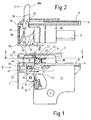
- FIG. 1 shows a top view of a cutting device, as was described in our older European application with the publication number 0711637, in a printing device which has a printing device and in which a cassette is inserted.
- the reference number 2 denotes a housing of the printing device which has a cassette receiving space.
- the printing device has a print head 10 and a counter-pressure roller 12 which is operatively connected to the print head in order to print on an image receiving tape T.
- the print head 10 and the counter-pressure roller 12 are mounted on the base plate 4 in the interior of the housing 2. The print head 10 can be moved from the operating position shown in FIG.
- Reference numeral 14 denotes a cassette inserted in the cassette accommodating space.
- the cassette 14 contains a supply of ink ribbon and image receiving tape, which are passed in mutual overlap between the platen roller and the printhead. The ink ribbon is then rewound into the cassette 14 while the image receiving tape is being transported out of the printer.
- the reference numeral 16 designates the printing zone through which the image receiving ribbon and the ribbon are guided in mutual overlap
- the reference numeral 18 denotes the zone in which the ribbon comes out of the Printer emerges. Between zones 16 and 18 is an area in which the cutting process takes place, as will be described in more detail later.
- the cutter consists of two main parts.
- the first part has a cutting body 20 on which a blade 22 is attached.
- the blade 22 serves to cut through the tape T in its entire thickness, whereby it enters a slot 24, which is located in the cassette 14 at a first cutting location C1.
- the cutting body 20 moves on supports 56, 58.
- the cutting body 20 On its surface adjacent to the tape T, the cutting body 20 has a tape holding clamp 28 in order to hold the tape T against a support surface of the cassette 14 during the cutting process.
- the reference number 26 denotes one of two strap holding springs assigned to the respective support 56, 58.
- the tape is a multi-layer tape with at least an upper layer, an adhesive layer and a backing layer which is detachable from the adhesive layer so that the upper layer can be attached to an object by means of the adhesive layer.
- the top layer of the tape is printed with an image or information.
- the upper layer of the tape T is on the right in the picture on the side facing the print head.
- the second part of the cutting device has a blade carrier 30, the so-called tab cutting blade 32 wears.
- the carrier 30 for the tab cut blade is mounted in a tab cut spring body 34, which in turn is resiliently biased against a tab cut support part 36 of the printer.
- This part of the cutting device also has a so-called roller anvil 38.
- the roller anvil 38 is rolled down against the tab cutting blade 32, a cut being made gradually over the width of the band T. The depth of cut is controlled so that the cut runs only through the upper band layer, while the back layer remains intact.
- the roller anvil 38 can be seen more clearly from FIG. 2, which represents a section along the line II-II according to FIG. 1.
- the anvil has an arcuate surface 3 and an actuating part 38a.
- Figures 1 and 2 show the roller anvil in its starting position.
- the movement of the roller anvil 38 is controlled by two guides, namely a first guide 40 facing the housing 2 of the printer and a second guide 42 facing inward of the cassette receiving space.
- the guides 40, 42 are provided with guideways for the movement of the Rollambosses 38 to control.
- the anvil has two projections, for example in the form of balls or pins, which are arranged in the vicinity of the respective ends of its arcuate surface 3. The pins are not shown in FIG.
- the corresponding pins arranged on the side of the anvil facing the viewer and which cooperate with corresponding guideways in the guide 40 are not shown in FIG. 2 for reasons of clarity. Of course, it is not absolutely necessary to form-fit the anvil on both sides. A single guide on one side can be sufficient.
- the cutting body 20 has a guide path 50 shown in FIG. 2, in which the actuating pin 48 attached to the anvil 38 is guided.
- the guideway 50 extends at an angle, as shown in FIG. 2.
- Fig. 2 shows the starting position.
- the return spring 8 which is arranged between the upstanding part 6 around the deflection roller 52 and the actuating pin 48 for the cutting body, is in a relaxed state.
- the guide pins are held in an upper part of the guideway.
- the cutting body 20 is in a position in which it holds the blade 22 at a distance from the band T.
- the actuating part 38a of the roller anvil 38 moves in the direction of arrow A according to FIG. 2. The movement of the anvil is controlled by the movement of the guide pins in the guideway.
- the movement is controlled in such a way as to ensure that the arcuate anvil surface rolls off the surface of the tab cut blade carrier 30, the tape being gradually provided with a tab cut as it passes the second cutting location C2.
- Guide pins and guideway are positioned to ensure accurate, reproducible roll motion.
- FIG. 3 shows a practical embodiment of a cutting device according to an embodiment of the invention.
- This cutting device is provided for those cases in which a cassette such as the cassette 14 shown in FIG. 1 does not have a support wall for the tape with a slot 24, but instead closes with a guide part behind the printing location.
- the cutting device is thus arranged completely outside the cassette boundary, where the tape comes out of the cassette.
- the cassette is not required to contain both an image receiving tape and a thermal transfer tape.
- the thermal transfer belt could be accommodated in a separate cassette, or it could be dispensed with entirely.
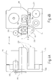
- FIG. 4B shows an ink ribbon cassette 214, in which there is a supply of ink ribbon or thermal transfer ribbon, and a substrate cassette 216, in which a supply of image receiving tape is located.
- the image receiving tape and the ink ribbon are passed through each other in registration between the print head 210 and the platen roller 212 to perform a printing operation.
- FIG. 4A is a view from the side of FIG. 4B in the direction of arrow IV. It can thus be seen that the base plate 222 of the printing device carries the ink ribbon cassette 214 and the carrier cassette 216. FIG. 4A also shows how the tape T emerges from the device in the direction of the viewer.
- the cutting device 220 itself will now be described in more detail below.
- the cutting device has a blade carrier 100 in which a full cut blade 102 and a tab cut blade 103 are held, the former serving to make a cut extending through the total thickness of all layers of a multilayer tape, while the latter is used to cut through only one or more layers of a multilayer tape is to be carried out, the back layer remaining intact.
- the cutting device also has an anvil holder 104 which carries two "roller anvils" 106, 108.
- the first roller anvil 106 has the function of interacting with the full cut blade 102, while the second roller anvil 108 serves to interact with the tabular cutting blade 103.
- the anvil holder 104 is in the form of a central shaft rotatable about an axis AA.
- the roll anvils each have a narrow circumferential slot 106a and 108a.
- the slots are aligned with the blade assigned to them in such a way that there is no direct contact between the blade and the anvil.
- Fig. 3 shows a schematic representation of the tape T when leaving the cassette and during its further transport to the cutting device in the direction of arrow B.
- the cutting locations C1 and C2 are arranged at a distance from one another in order to carry out a full cut at the cutting location C1 and a tabular cut at the cutting location C2, the cutting mode desired in each case in the selected type described below.
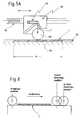
- FIG. 5A shows the cutting device from its front side. This view is obtained by looking at the tape T along its way out of the cassette.
- the blade carrier 100 can thus be viewed in section, the full-cutting blade 102 being visible.
- the width of the band is designated w. This value is variable depending on the width of the tape inserted.
- the anvil holder 104 is mounted on a carriage 110 and is biased against the blade carrier 100 by the action of a spring 112 under constant force. The downward force is indicated by the arrow F. Under the action of a lead screw 114 driven by a motor, the carriage can be moved back and forth across the width of the belt T. When the carriage is driven by the lead screw, the roller anvils 106 and 108 are rotated, thereby cutting the tape T against the action of the blades at the cutting locations C1 and C2.
- FIG. 5B shows a section through the carriage 110, the mode of operation of which can be seen more clearly.
- the guide spindle 114 extends through an opening 115 in the slide 110 and is received in threaded nuts 117 at both ends of the opening. Rotation of the lead screw 114 thus causes the carriage 110 to move laterally in FIG. 5B.
- the carriage 110 consists of a main part 110a and a pivotable part 110b.
- the pivotable part 110b has one Recess 119 for receiving the holder or shaft 104 of the roller anvil.
- the pivotable part 110b is hinged to the main part 110a by means of a hinge 110c.
- spring 112 acts between main body 110a and pivotable body 110b to apply downward force F, as set forth above with reference to FIG. 5A.
- the slide is made in one piece, the pivotable part 110b being open to the main part 110a. This is shown in more detail in Fig. 5C. Because the carriage is made in one piece, the spring can be attached to the carriage and the pivotable part 110b can be folded back in the direction of the arrow Y, which simplifies production.
- the full-cut blade can either be put into or out of operation, so that the cutting device either carries out a full cut with a tabular cut or only a tabular cut.
- a cutting device that offers this possibility is shown in FIG. 6.
- FIG. 6 is a view corresponding to FIG. 3, the roller anvils 106 and 108 being shown attached to the anvil holder 104.
- the full cut blade 102 is mounted on a cutting blade pin 116 which is actuated by a slide 118.
- the slide 118 is an essentially flat component with an elongated part which is guided in a guide groove 120 formed in the blade carrier 100.
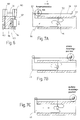
- 7A shows an end view of the cutting device, the slide being shown in more detail. 7A shows the slider in its retracted position.
- the slide 118 On its right side in FIG. 7A, the slide 118 has a cam part 122, against which the cutting blade pin 116 bears. On its left side in FIG. 7A, the slide 118 has an actuating part 124 extending upward from the elongated portion of the slider. The actuating part 124 carries an actuating element 126 which extends in the longitudinal direction of the blade carrier, ie in the direction in which the carriage 110 moves. There is a stop 128 at its end. The arrangement of the stop 128 is as described below.
- Figure 7A shows the anvil holder 104 in its home position, at the far left end of its path, as shown in Figure 7A. In this position, it holds the actuating part 124 of the slider 118 so that the cam part 122 holds the cutting blade pin 116 down, the full cutting blade 102 disengaging. If the anvil holder 104 now rolls from its starting position to the right in FIG. 7A in the direction of the arrow C, only a tabular cut is carried out on the tape.
- the anvil bracket 104 has two stop positions, an inner stop position as shown in FIG. 7B and an outer stop position as shown in FIG. 7C.
- the shaft of the anvil holder lies just against the stop 128 of the actuating element 126 and thus does not cause the slide 118 to move.
- the full cut blade thus remains disengaged and when the anvil holder returns to its starting position on its return stroke from the inner stop position also not a full cut on the label.
- the anvil holder 104 When the anvil holder 104 is returned to its starting position, a full cut is thus made through the band. If a full cut is made, the anvil holder 104, in the final phase of the return stroke, moves the actuating part 124 of the slider 118 back to the left when the anvil holder reaches its starting position. Thus, the slider 118, through its cam portion 122, causes the cutting blade pin 116 to move downward so that the full cutting blade 102 is in its inactive position. The next extension stroke of the anvil holder 104 does not result in a full cut. In other words, the present embodiment only allows a full cut to be made during the return stroke of the anvil holder 104.
- Fig. 8 shows the starting position, the inner stop position and the outer stop position with respect to the maximum width of the tape T.
- This arrangement enables a user to choose whether a full cut with tabular cut or only a tabular cut should be carried out. This can be done automatically with the aid of the arrangement according to FIG. 9.
- the blade carrier is not shown in Fig. 9, but the carriage 110 with the roller anvil 106. As described above in connection with Fig. 5A, the carriage 110 runs on a guide spindle 114.
- Reference numeral 200 denotes a DC motor with which the Leading spindle is driven via a reduction gear pair 202.
- a first leaf spring switch 204 is provided, which detects the starting position of the anvil holder 104.
- the detection of the inner and outer stop position is achieved by a second leaf spring switch 206, which detects the revolutions of a second gear wheel of the reduction gear pair 202. This can be done, for example, with the help of a front cam on the second gear wheel. With each revolution of the guide spindle 114, a pulse is thus generated at the second leaf spring switch 206, whereby a simple rising encoder is formed. 10 shows the respective signals from the leaf spring switches 204 and 206.
- the leaf spring switches 204 and 206 are referred to here as diagnostic switches.
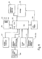
- FIG. 11 shows a block diagram of a circuit arrangement for a printing device for carrying out the above-mentioned feature.
- FIG. 11 shows a central controller 300 for the printing device, which has a microprocessor with a read-only memory ROM 302 and a random access memory RAM 304.
- the controller 300 is connected to an LCD driver 309 for controlling a display device 308 of the printing device. As indicated by the jagged line across the connection between the controller 300 and the LCD driver 309, the display device and associated driver may be located away from the printing device.
- the controller 300 also communicates with a keyboard or other input device 306 to obtain information about data to be printed, cutting operations, and the like.
- a large number of keys are provided, which are shown, for example, as keys 320, 310, 312 and 316.
- keys 320, 310, 312 and 316 are shown, for example, as keys 320, 310, 312 and 316.
- the keyboard is placed away from the printing device.
- the print head and the tape drive motor carry out the printing and feed processes, controlled by the control, in a manner known per se.
- the controller 300 is also connected to a two-way motor control circuit 317 which controls the operation of the cutting drive motor 200 in a manner to be described in more detail below.
- the controller 300 receives information from the cut diagnostic switches 204, 206 shown in FIG. 9.
- the controller 300 is also connected to cartridge diagnostic switches 301, which are located in the cartridge receiving space of the printing device and provide parameters relating to the cartridge to the controller 300 for Example of the type of tape, its width, etc.
- control circuit 300 receives corresponding signals from the cutting diagnostic switches 204, 206, by means of which it can determine the position of the carriage. It can therefore cause the direction of movement of the anvil holder to be reversed either at the inner or outer stop position.
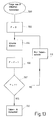
- step 400 A more detailed illustration is shown in FIG. 12, in which the start of a cutting process is shown at step 400.
- a cutting operation can be triggered by the user pressing a cutting key on the keyboard 306 or automatically by the device itself after it has printed a certain length of labels.
- step 402 control checks whether a full cut is required. This must be set by the user at the time the label is formatted or when a cutting operation is initiated. Depending on the result of the test, a number N is set which is equal to the number of switching pulses to be expected from the diagnostic leaf spring switch 206. If a full cut is required, the number N is set to N2, while for a tabular cut alone, the number N is set to N1.
- N1 is logically smaller than N2 because of the extension stroke of the carriage 110 is shorter in the case of a tab cut than in the case of a full cut on the return stroke.
- Step 404 the carriage 110 is moved outward by starting the engine 200.
- Diagnostic leaf spring switch 204 determines when the carriage has passed the home position, as indicated by transition 405 in FIG. 10. This transition is recognized in step 406 and the controller then counts the increasing switching pulses derived from the diagnostic leaf spring switch 206. If N equals the preset number (N1 or N2, depending on the determination in steps 403a, 403b), the direction of rotation of the motor is reversed in step 407 to drive the carriage 110 inwards. If the signal for the starting position is reached (step 408), the sequence of steps is ended (step 409).
- the diagnostic leaf spring switch 204 (see Figure 9) is used to turn off the DC motor 200 when the anvil bracket 104 returns to its home position. This is not caused directly, but rather by the software of the controller 300.
- a user can thus request labels with or without a full cut via a user interface of the printing device.
- a sequence of labels can also be produced in the strip mode, and after the last of these labels the control circuit can cause the cutting device to carry out a full cut with the last tab cut in order to separate the label strip from the printing device. Further details on the manner in which labels can be produced in the so-called "strip mode" are disclosed in our older European patent application with the publication number 0578372. The content of this application is hereby incorporated by reference.
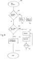
- the flow chart in Fig. 13 shows how a sequence of labels can be produced in the strip mode, the strip being cut off at the end with a full cut.
- the flowchart in Fig. 13 begins at the point where a user has requested a sequence of p labels, the individual label being separated from its adjacent label only by a tab cut, but the labels remaining attached to a common strip of backing tape. This is identified in the flowchart by step 500.
- step 504 the processor then prints the first label in the sequence.
- step 506 p is increased by 1 and compared in step 507 with P. It is clear that p is not equal to P on the first label, and consequently the full cut blade is put out of order as explained above. Thus, only a tab cut is performed, as shown in step 510.
- the user can also use the data entry keys to enter a number which then appears on the display in block 601 next to the selected option.
- the processor determines in step 602 whether one or more copies have been requested. If it is only a single label, the label is printed at step 604, whereupon the cutting process at step 606 includes a full-cut tab cut.
- the processor recognizes this at step 608. If a full cut is selected, a sequence of copies of a label is printed and cut off individually with a full cut, as illustrated in a series of steps 610, 612 and 614.
- the processor In contrast to a full cut, the processor must also take the lead length of a label into account when working in strip mode. This can be done in the manner described in EP 578372.
- the user can request multiple copies of the same label.
- the printer can count the number of copies and, if desired, display this to a user.
- the display shows how many copies have been printed or are still to be printed.
- the printing device can be set up so that it delivers so-called increasing copies. This means that the printer can print a series of labels with each label assigned a number, with subsequent labels having that number plus 1.
- the user can select the number of labels that will be printed with the same increasing number. For example, he could select 3 copies of labels that have the same increasing number.
- the lead length of a label can be reduced by starting a printing process in such a way that part of the label is printed, the printing is then stopped to make a tab cut after the tape is fed a predetermined length, and then the full label is printed. This enables shorter labels to be produced, which means that tape consumption is reduced to a minimum.
Landscapes
- Life Sciences & Earth Sciences (AREA)
- Forests & Forestry (AREA)
- Engineering & Computer Science (AREA)
- Mechanical Engineering (AREA)
- Handling Of Sheets (AREA)
Applications Claiming Priority (4)
| Application Number | Priority Date | Filing Date | Title |
|---|---|---|---|
| GB9610028 | 1996-05-14 | ||
| GBGB9610028.4A GB9610028D0 (en) | 1996-05-14 | 1996-05-14 | A cutting mechanism |
| GB9614112A GB2313081A (en) | 1996-05-14 | 1996-07-05 | A printing device with automatic cut |
| GB9614112 | 1996-07-05 |
Publications (3)
| Publication Number | Publication Date |
|---|---|
| EP0807524A2 true EP0807524A2 (fr) | 1997-11-19 |
| EP0807524A3 EP0807524A3 (fr) | 1998-08-26 |
| EP0807524B1 EP0807524B1 (fr) | 2003-07-02 |
Family
ID=26309329
Family Applications (1)
| Application Number | Title | Priority Date | Filing Date |
|---|---|---|---|
| EP19970105713 Expired - Lifetime EP0807524B1 (fr) | 1996-05-14 | 1997-04-07 | Appareil d'impression avec un dispositif automatique de coupe |
Country Status (2)
| Country | Link |
|---|---|
| EP (1) | EP0807524B1 (fr) |
| DE (1) | DE59710365D1 (fr) |
Cited By (4)
| Publication number | Priority date | Publication date | Assignee | Title |
|---|---|---|---|---|
| EP0947341A1 (fr) * | 1998-03-31 | 1999-10-06 | Brother Kogyo Kabushiki Kaisha | Imprimante pour ruban |
| EP1027967A1 (fr) * | 1999-02-11 | 2000-08-16 | GRETAG IMAGING Trading AG | Dispositif de coupe |
| EP1334809A3 (fr) * | 2002-02-06 | 2005-01-05 | Brady Worldwide, Inc. | Contrôle de la profondeur de coupe d'un traceur pendant la coupe d'étiquettes |
| WO2005123355A1 (fr) * | 2004-06-18 | 2005-12-29 | Onamor Di Giorgi Francesco & C. | Machine a decouper les materiaux fibreux |
Family Cites Families (3)
| Publication number | Priority date | Publication date | Assignee | Title |
|---|---|---|---|---|
| GB1396887A (en) * | 1971-06-17 | 1975-06-11 | Morris L J | Devices for cutting or scoring sheet material |
| US5458423A (en) * | 1992-06-11 | 1995-10-17 | Esselte Dymo N.V. | Tape cutting apparatus |
| US5436646A (en) * | 1993-05-21 | 1995-07-25 | Calcomp Inc. | Cam operated cutter for roll-fed pen plotters |
-
1997
- 1997-04-07 DE DE59710365T patent/DE59710365D1/de not_active Expired - Lifetime
- 1997-04-07 EP EP19970105713 patent/EP0807524B1/fr not_active Expired - Lifetime
Cited By (5)
| Publication number | Priority date | Publication date | Assignee | Title |
|---|---|---|---|---|
| EP0947341A1 (fr) * | 1998-03-31 | 1999-10-06 | Brother Kogyo Kabushiki Kaisha | Imprimante pour ruban |
| US6113294A (en) * | 1998-03-31 | 2000-09-05 | Brother Kogyo Kabushiki Kaisha | Tape printer |
| EP1027967A1 (fr) * | 1999-02-11 | 2000-08-16 | GRETAG IMAGING Trading AG | Dispositif de coupe |
| EP1334809A3 (fr) * | 2002-02-06 | 2005-01-05 | Brady Worldwide, Inc. | Contrôle de la profondeur de coupe d'un traceur pendant la coupe d'étiquettes |
| WO2005123355A1 (fr) * | 2004-06-18 | 2005-12-29 | Onamor Di Giorgi Francesco & C. | Machine a decouper les materiaux fibreux |
Also Published As
| Publication number | Publication date |
|---|---|
| EP0807524B1 (fr) | 2003-07-02 |
| DE59710365D1 (de) | 2003-08-07 |
| EP0807524A3 (fr) | 1998-08-26 |
Similar Documents
| Publication | Publication Date | Title |
|---|---|---|
| DE69317131T2 (de) | Bandschneidegerät | |
| DE68914694T2 (de) | Bandzuführvorrichtung für Thermo-Drucker. | |
| DE69410025T2 (de) | Kassette für Thermo-Drucker | |
| DE69104694T2 (de) | Thermodrucker und Kassette dafür. | |
| DE69411600T2 (de) | Druckvorrichtung mit Kassette | |
| DE60204933T2 (de) | Schneidvorrichtung für einen Drucker | |
| DE69332723T2 (de) | Streifenkassette und Druckvorrichtung | |
| DE3914184C2 (de) | Streifenschneider | |
| DE69900396T2 (de) | Verfahren und Vorrichtung zum Drucken | |
| DE69320893T2 (de) | Streifendrucker | |
| DE68923715T2 (de) | Thermo-Drucker und seine Bandkassette. | |
| DE69602868T2 (de) | Drucker und zusammengesetzte Kassette für diesen Drucker, bestehend aus Druckband- und Farbbandkassette | |
| DE69008313T2 (de) | Drucker zum Bedrucken von mehreren Papierarten. | |
| EP0807525B1 (fr) | Dispositif de coupe | |
| DE69702075T2 (de) | Streifendruckgerät und streifenhaltegehäuse | |
| DE2830703A1 (de) | Einrichtung zur papiereinfuehrung, zum papiertransport und zur papierausgabe in einem schnelldrucker | |
| EP0773110B1 (fr) | Ensemble de cassette à bande et appareil d'impression | |
| DE69315745T2 (de) | Thermodrucker | |
| DE69619746T2 (de) | Gerät zum Herstellen von Stempeln, sowie Mechanismus zum Wechseln von Funktionen, Belichtungssystem und Erkennungsvorrichtung für das Material zur Stempelherstellung | |
| DE3885307T2 (de) | Bildaufzeichnungsgerät. | |
| DE69405059T2 (de) | Schneidemaschine für Bänder | |
| DE69700482T2 (de) | Maschine und Verfahren zum vorbestimmten Bearbeiten von Blattmaterial mit einer Länge verbrauchbaren Bandes | |
| DE602004007204T2 (de) | Banddruckgerät und Banddrucksystem | |
| DE69018377T2 (de) | Drucker für zwei Arten Papier. | |
| DE69513310T2 (de) | Schneidsystem für Druckvorrichtung |
Legal Events
| Date | Code | Title | Description |
|---|---|---|---|
| PUAI | Public reference made under article 153(3) epc to a published international application that has entered the european phase |
Free format text: ORIGINAL CODE: 0009012 |
|
| AK | Designated contracting states |
Kind code of ref document: A2 Designated state(s): DE FR GB |
|
| PUAL | Search report despatched |
Free format text: ORIGINAL CODE: 0009013 |
|
| AK | Designated contracting states |
Kind code of ref document: A3 Designated state(s): DE FR GB |
|
| 17P | Request for examination filed |
Effective date: 19980714 |
|
| 17Q | First examination report despatched |
Effective date: 19990924 |
|
| GRAG | Despatch of communication of intention to grant |
Free format text: ORIGINAL CODE: EPIDOS AGRA |
|
| GRAG | Despatch of communication of intention to grant |
Free format text: ORIGINAL CODE: EPIDOS AGRA |
|
| GRAH | Despatch of communication of intention to grant a patent |
Free format text: ORIGINAL CODE: EPIDOS IGRA |
|
| GRAH | Despatch of communication of intention to grant a patent |
Free format text: ORIGINAL CODE: EPIDOS IGRA |
|
| GRAA | (expected) grant |
Free format text: ORIGINAL CODE: 0009210 |
|
| AK | Designated contracting states |
Designated state(s): DE FR GB |
|
| REG | Reference to a national code |
Ref country code: GB Ref legal event code: FG4D Free format text: NOT ENGLISH |
|
| GBT | Gb: translation of ep patent filed (gb section 77(6)(a)/1977) | ||
| REF | Corresponds to: |
Ref document number: 59710365 Country of ref document: DE Date of ref document: 20030807 Kind code of ref document: P |
|
| ET | Fr: translation filed | ||
| PLBE | No opposition filed within time limit |
Free format text: ORIGINAL CODE: 0009261 |
|
| STAA | Information on the status of an ep patent application or granted ep patent |
Free format text: STATUS: NO OPPOSITION FILED WITHIN TIME LIMIT |
|
| 26N | No opposition filed |
Effective date: 20040405 |
|
| REG | Reference to a national code |
Ref country code: FR Ref legal event code: CD |
|
| REG | Reference to a national code |
Ref country code: FR Ref legal event code: PLFP Year of fee payment: 19 |
|
| PGFP | Annual fee paid to national office [announced via postgrant information from national office to epo] |
Ref country code: DE Payment date: 20150429 Year of fee payment: 19 Ref country code: GB Payment date: 20150427 Year of fee payment: 19 |
|
| PGFP | Annual fee paid to national office [announced via postgrant information from national office to epo] |
Ref country code: FR Payment date: 20150417 Year of fee payment: 19 |
|
| REG | Reference to a national code |
Ref country code: DE Ref legal event code: R082 Ref document number: 59710365 Country of ref document: DE Representative=s name: PAGE WHITE & FARRER, GB |
|
| REG | Reference to a national code |
Ref country code: DE Ref legal event code: R119 Ref document number: 59710365 Country of ref document: DE |
|
| GBPC | Gb: european patent ceased through non-payment of renewal fee |
Effective date: 20160407 |
|
| REG | Reference to a national code |
Ref country code: FR Ref legal event code: ST Effective date: 20161230 |
|
| PG25 | Lapsed in a contracting state [announced via postgrant information from national office to epo] |
Ref country code: FR Free format text: LAPSE BECAUSE OF NON-PAYMENT OF DUE FEES Effective date: 20160502 Ref country code: DE Free format text: LAPSE BECAUSE OF NON-PAYMENT OF DUE FEES Effective date: 20161101 Ref country code: GB Free format text: LAPSE BECAUSE OF NON-PAYMENT OF DUE FEES Effective date: 20160407 |