EP0807569A2 - Device for disengaging a bicycle chain - Google Patents
Device for disengaging a bicycle chain Download PDFInfo
- Publication number
- EP0807569A2 EP0807569A2 EP97103188A EP97103188A EP0807569A2 EP 0807569 A2 EP0807569 A2 EP 0807569A2 EP 97103188 A EP97103188 A EP 97103188A EP 97103188 A EP97103188 A EP 97103188A EP 0807569 A2 EP0807569 A2 EP 0807569A2
- Authority
- EP
- European Patent Office
- Prior art keywords
- chain
- support
- swivel
- pivot
- profiles
- Prior art date
- Legal status (The legal status is an assumption and is not a legal conclusion. Google has not performed a legal analysis and makes no representation as to the accuracy of the status listed.)
- Granted
Links
Images

Classifications
-
- B—PERFORMING OPERATIONS; TRANSPORTING
- B62—LAND VEHICLES FOR TRAVELLING OTHERWISE THAN ON RAILS
- B62M—RIDER PROPULSION OF WHEELED VEHICLES OR SLEDGES; POWERED PROPULSION OF SLEDGES OR SINGLE-TRACK CYCLES; TRANSMISSIONS SPECIALLY ADAPTED FOR SUCH VEHICLES
- B62M9/00—Transmissions characterised by use of an endless chain, belt, or the like
- B62M9/16—Tensioning or adjusting equipment for chains, belts or the like
-
- F—MECHANICAL ENGINEERING; LIGHTING; HEATING; WEAPONS; BLASTING
- F16—ENGINEERING ELEMENTS AND UNITS; GENERAL MEASURES FOR PRODUCING AND MAINTAINING EFFECTIVE FUNCTIONING OF MACHINES OR INSTALLATIONS; THERMAL INSULATION IN GENERAL
- F16H—GEARING
- F16H7/00—Gearings for conveying rotary motion by endless flexible members
- F16H7/24—Equipment for mounting belts, ropes, or chains
Definitions
- the invention relates to a device for disengaging a bicycle chain and transferring it from a sprocket of the rear wheel to a guide connected to the bicycle frame for supporting the chain in the extended position for the purpose of disassembling the rear wheel.
- a sickle-shaped guide edge can be changed in the axial direction by means of a lever between two positions.
- the leading edge is pushed against the outer sprocket, after which the chain is placed over the sprocket against which the leading edge rests by appropriate actuation of the chain changer of the gear shift of the bicycle.
- the rear wheel can then be removed.
- the chain remains on the leading edge, being tensioned between the leading edge and the front sprocket by the chain changer.
- the bicycle chain can be placed on the leading edge from a rear sprocket without the chain having to be manipulated.
- the prerequisite is that the bicycle is equipped with a sprocket gear shift.
- the invention has for its object to improve a device of the type mentioned in such a way that it does not require additional axial space and that it can also be used in bicycles without sprocket gear shift, ie in bicycles with hub gear shift or in bicycles without gear shift is usable.
- the guide comprises a support element which can be pivoted in the chain plane and which can be pivoted from a starting position removed from the chain into a support position which engages the chain from the inside.
- a fixed nor an axially displaceable support element is therefore provided; instead, the support element is pivoted in the plane spanned by the upper and the lower chain center until it grips the chain from the inside and, as it were, lifts it off the sprocket.
- a support element which has at least one arched support edge in the direction of the chain, which in the support position rests on the webs of the chain links. The support edge is pivoted in the chain direction until it lifts the chain out of the toothing and, as it swings in, takes over its position to a certain extent.
- Support element for bicycles with hub gears or without gears, where there is very little free chain length, namely only according to the sag of the chain, that shows Support element according to another proposal according to the invention at least one support surface which is curved in the direction of the chain and which, in the support position, rests on the tension members of one side of the chain.
- the support element can also have two support surfaces for the opposing tension members of the chain, the support surfaces being expediently designed as webs directed against the ring gear of a U-shaped swivel profile enclosing the chain from three sides.
- the chain is lifted in a radial direction as a result of the pivoting movement of the support surface or both support surfaces, each of which engages in the chain from the side, a very small stroke being sufficient.
- the wheel Under the chain retained by the support surfaces, the wheel can emerge from the bearing slot after loosening the wheel nuts on both sides.
- the chain is supported in the same plane after the transfer and that the supporting edge or supporting surfaces of the supporting elements are pivoted in the radial direction within the chain plane, the plane spanned by the upper and lower chain center being the chain plane is understood.
- manually operable levers are provided, which are expediently pivoted after the rear wheel has been released, the chain being taken over by the support element during the increasing pivoting while the rear wheel exits the bearing slot. Without having to touch the chain with your hands, it is stretched between the support elements and the front sprocket after the rear wheel has been removed.
- the invention thus facilitates the transportation of the bicycle frame when the wheels are removed.
- the rear wheel can also be easily installed by pushing it into the bearing slots until the associated sprocket engages the chain again, at the same time pivoting the support elements out of engagement.
- the support element is articulated adjacent to the rear wheel axle on the frame part forming its bearing slot, in such a way that it can be pivoted about the articulation point from its front starting position into its rear support position.
- This embodiment is suitable is particularly suitable for a support element with an arched support edge.
- the support edge can have at least one tooth which projects radially outwards and engages in the chain links; by means of one or more such teeth, the support element can also be transported with the aid of the chain, in that the chain is driven by turning the pedals when the bicycle is unloaded.
- the drive direction depends on whether the support element is pivoted with its support edge around its respective articulation point from the inside of the chain against its upper or lower run.
- Another advantageous embodiment consists in that the support edge is formed on a segment sheet which is bent axially inwards on its circumference and has a radially outwardly bent edge in the form of the support edge on its inner edge.
- the segment sheet is advantageously articulated via a swivel bearing to a fastening tab attached to the inside of the frame part adjacent to the outermost sprocket.
- An axially outwardly projecting finger lever is provided on the segment plate for pivoting it. The user therefore only operates this finger lever; his hands touch when handing over the chain to the support element not the chain itself. The same applies to the reassembly of the rear wheel.
- the pivoting profile is arcuate and at one end can be pivoted about a frame-fixed pivot point located behind the chain in the middle of the chainring, such that the Support areas in the area of the other end of the swivel profile support the chain inwards.
- a particularly advantageous embodiment provides that two swivel profiles are arranged approximately symmetrically to the horizontal through the average height of the chain link, which can be actuated by a common swivel drive.
- the pivot drive expediently comprises a pivot cam which can be actuated by means of a pivot lever and which cooperates with projections on the mutually facing ends of the pivot profiles in such a way that the pivot profiles with their opposite ends are spread apart from the inside against the chain.
- Characterized in that the pivot cam is substantially elongated, it increases the distance between the projections accordingly with a rotation of 90 ° with the result that the outer ends of the Swivel cams can be spread from the inside against the chain.
- a position of the pivot points favoring the lever effect for pivoting the pivot profiles is achieved in that the frame part forming the bearing slot is extended to the rear by means of a frame plate receiving the pivot points for the pivot profiles.
- the swivel profiles are articulated so eccentrically at the swivel points of the frame plate that the mutually facing ends of the swivel profiles move towards the chain when they are spread. This movement allows the chain to yield inwards, with the previously released rear wheel emerging from the bearing slots simultaneously with the pivoting of the pivoting profiles.
- a suitable pivot lever for actuating the pivot cam is bent from below around the associated stub shaft, which forms the upper stop position corresponding to the starting position.
- the swivel lever can additionally have an upwardly directed mandrel just behind the axle stub for disengaging the axle stub from the bearing slot. So while pivoting the pivot lever the pivot profiles are increasingly spread apart, the mandrel ensures the disengaged rear wheel at the same time.
- FIG. 1 to 6 show a first embodiment of the device according to the invention.
- this embodiment is suitable for bicycles with hub gear shift or without gear shift, in which the sag of chain 1 is limited. This is the reason why the chain can only be lifted off the sprocket to a limited extent for the purpose of transferring it from a sprocket to a support element.
- This lifting is provided by the two pivot profiles 2, 3, which can be pivoted radially outward with their non-articulated ends by rotating a pivot cam 4 according to the arrows P1, P2.
- the two pivot profiles 2, 3 can each be pivoted with their ends oriented towards the center of the chain link about pivot points 5 of a frame plate 6, in which short eccentric levers 7 are connected, which are connected to the pivot profiles in a rotationally fixed manner.
- the ends of the swivel profiles 2, 3 oriented towards the center of the chain arch migrate inward when they are spread out, as shown in FIG. 3, so that after the chain is released by the gearwheel, more chain length is available for spreading the chain.
- the frame plate 6 has, as can be seen in Fig. 2, an angled mounting flange 8 which comprises the end of the frame part 10 containing the bearing slot 9 for the rear wheel and by means of a through screw 11 with the latter connected is.
- the two swivel profiles 2, 3 are held in their starting position by means of tension springs 12, which are anchored to the frame plate 6, so that they do not inadvertently come into engagement with the chain 1.
- the pivot cam 4 is seated on a pin 13 pivotably mounted in the frame part 10, at the other end of which a pivot lever 14 is fastened. With a corresponding bend, the pivot lever 14 engages under the side stub axle 15 of the rear wheel, the hub 16 of which is only indicated by an outline.
- the swivel lever 14 has on the rear side of the stub axle 15 an upwardly projecting mandrel 18 which, when the swivel lever 14 is actuated in the direction of arrow P3, moves against the stub axle 15 and consequently disengages it from the bearing slot 9.
- the pivot cam 4 is rotated from its horizontal position according to FIG. 1 into its vertical spread position according to FIG. 3, the rotational position of which is shown in FIG. 6 at a pivot angle of approximately 45 °.
- the rear wheel already released before the pivot lever 14 is actuated is first pushed with the aid of the mandrel 18 during pivoting of the pivot lever 14 then casually travels forward through the sloping bearing slot 9 until it comes out of engagement with the chain links.
- the chain 1 is held on the inward-facing support surfaces 19 of the swivel profiles, as shown in FIGS. 3 and 6 and enlarged in FIG. 4.
- the two support profiles 2, 3 include the sprocket 17 in the area of the chain 1 in an approximately U-shaped manner, as is illustrated in FIG. There you can also see the pivot point 5 of the support profile 2 in the frame plate 6.
- the pivot cam 4 interacts with this, on both sides, inwardly projecting projections 20 of the support profiles 2, 3. Their flanks adjacent to the swivel cam 4 are always held in contact by means of the tension springs 12 and are correspondingly moved apart when the swivel cam 4 is swiveled until the maximum swivel position shown in FIG. 3 is reached.
- FIG. 6 shows a simplified illustration in that the frame plate 6 is omitted for clarity.
- FIG. 4 shows - after the gear 17 has been disengaged - a chain link abutting against the two support surfaces 19 with the lateral tension links 21, the tension links 21 of which are connected to one another via a web 22.
- FIG. 7 to 10 show a further embodiment of the invention, wherein the frame part 10 with the longitudinal slot 9 for receiving the wheel axle 23 of the rear wheel has at its lower end a bearing eye 33 for articulating a lever for tightening the chain in a chain gear shift. Since in this embodiment there is sufficient chain length for the transfer of the chain 1 to a support element designed as a segment plate 24, its simple swivel mounting around an articulation point 25 on the frame 10 is sufficient.
- the segment plate 24 has a support edge 26 on its circumference with a radially projecting tooth 27 at the top.
- the articulation point 25 of the segment plate 24 is mounted in a fastening tab 31 which comprises the frame part 10 in its rear area and which is fastened in the frame part 10 by means of two screws 32.
- the tooth 27 of the support edge 26 facilitates the pivoting of the segment plate 24 in the direction of the arrow P4 in that the chain 1 is moved to the left according to the arrow P5 after the tooth 27 engages in it.
- the segment plate 24 is automatically carried along by the tooth 27 until the tooth 27 has reached its end position shown in FIG. 9, in which it is supported with its rounded flank against a chain web 22.
- the segment sheet 24 is first bent along its circumference by 90 ° axially inwards, then again by 90 ° radially outwards, so that the support edge 26 thus formed is exactly in the plane of the outer ring gear 17 Chain connection between these and the chain engages, so that ultimately the support edge 26 engages approximately centrally on the inside of the chain stays 22.
Landscapes
- Engineering & Computer Science (AREA)
- Mechanical Engineering (AREA)
- General Engineering & Computer Science (AREA)
- Chemical & Material Sciences (AREA)
- Combustion & Propulsion (AREA)
- Transportation (AREA)
- Devices For Conveying Motion By Means Of Endless Flexible Members (AREA)
- Transmissions By Endless Flexible Members (AREA)
- Hand Tools For Fitting Together And Separating, Or Other Hand Tools (AREA)
- Steering Devices For Bicycles And Motorcycles (AREA)
Abstract
Bei einer Vorrichtung zum Auskuppeln einer Fahrradkette und deren Übergabe von einem Zahnkranz (17) des Hinterrads an eine mit dem Fahrradrahmen verbundene Führung zum Abstützen der Kette in gestreckter Stellung zwecks Demontage des Hinterrads ist vorgesehen, daß die Führung ein in der Kettenebene verschwenkbares Stützelement umfaßt, welches aus einer von der Kette (1) entfernten Ausgangsposition in eine in die Kette (1) von innen greifende Stützposition verschwenkbar ist. <IMAGE>In a device for disengaging a bicycle chain and transferring it from a sprocket (17) of the rear wheel to a guide connected to the bicycle frame for supporting the chain in the extended position for the purpose of dismantling the rear wheel, it is provided that the guide comprises a support element which can be pivoted in the chain plane. which can be pivoted from a starting position removed from the chain (1) into a supporting position which engages in the chain (1) from the inside. <IMAGE>
Description
Die Erfindung betrifft eine Vorrichtung zum Auskuppeln einer Fahrradkette und deren Übergabe von einem Zahnkranz des Hinterrads an eine mit dem Fahrradrahmen verbundene Führung zum Abstützen der Kette in gestreckter Stellung zwecks Demontage des Hinterrads.The invention relates to a device for disengaging a bicycle chain and transferring it from a sprocket of the rear wheel to a guide connected to the bicycle frame for supporting the chain in the extended position for the purpose of disassembling the rear wheel.
Bei einer bekannten Vorrichtung der genannten Art (US-3840251) ist eine sichelförmige Führungskante in axialer Richtung mittels eines Hebels zwischen zwei Stellungen veränderbar. Zwecks Übernahme der Fahrradkette wird die Führungskante gegen den äußeren Zahnkranz geschoben, wonach durch entsprechende Betätigung des Kettenwechslers der Gangschaltung des Fahrrads die Kette über den Zahnkranz, an welchem die Führungskante anliegt, gelegt wird.In a known device of the type mentioned (US-3840251), a sickle-shaped guide edge can be changed in the axial direction by means of a lever between two positions. In order to take over the bicycle chain, the leading edge is pushed against the outer sprocket, after which the chain is placed over the sprocket against which the leading edge rests by appropriate actuation of the chain changer of the gear shift of the bicycle.
Danach kann das Hinterrad entfernt werden. Die Kette verbleibt auf der Führungskante, wobei sie durch den Kettenwechsler zwischen der Führungskante und dem vorderen Kettenrad gespannt ist.The rear wheel can then be removed. The chain remains on the leading edge, being tensioned between the leading edge and the front sprocket by the chain changer.
Auf die erläuterte Weise kann die Fahrradkette von einem hinteren Zahnkranz auf die Führungskante abgelegt werden, ohne daß es dabei einer Manipulation der Kette bedarf. Voraussetzung ist allerdings, daß das Fahrrad mit einer Kettenrad-Gangschaltung versehen ist.In the manner described, the bicycle chain can be placed on the leading edge from a rear sprocket without the chain having to be manipulated. However, the prerequisite is that the bicycle is equipped with a sprocket gear shift.
Obige Voraussetzung trifft auch auf andere dem gleichen Zweck dienende bekannte Vorrichtungen zu (DE-2648928-A1, FR-7907474-A1), bei denen eine rahmenfeste Führungskante, welche bogenförmig um die Radachse verläuft, auf der Rahmeninnenseite dicht neben dem äußeren Zahnkranz der hinteren Antriebszahnräder vorgesehen ist.The above requirement also applies to other known devices serving the same purpose (DE-2648928-A1, FR-7907474-A1), in which a frame-fixed guide edge, which runs in an arc around the wheel axis, on the inside of the frame close to the outer ring gear of the rear Drive gears is provided.
Diesen beiden bekannten Lösungen ist gemeinsam, daß die Kette bei der Übergabe in axialer Richtung bewegt wird, bis sie sich außerhalb des äußeren Zahnkranzes befindet. Dazu ist ein entsprechender Platzbedarf in axialer Richtung erforderlich, was konstruktiv durch eine entsprechende Bemessung der Hinterrad-Achsstummel sowie der Hinterradgabel zu berücksichtigen ist.These two known solutions have in common that the chain is moved during the transfer in the axial direction until it is outside the outer ring gear. This requires a corresponding amount of space in the axial direction, which must be taken into account in the design by appropriate dimensioning of the rear wheel axle stub and the rear wheel fork.
Ein zusätzlicher Platzbedarf in axialer Richtung ist auch bei der aus der genannten US-PS 3840251 bekannten Vorrichtung erforderlich, um die axiale Verschiebung der Führungskante zwischen einer seitlichen Ausgangsposition und der Anlageposition am äußeren Zahnkranz zu ermöglichen.An additional space requirement in the axial direction is also required in the device known from the aforementioned US Pat. No. 3,840,251 in order to enable the axial displacement of the leading edge between a lateral starting position and the contact position on the outer ring gear.
Demgegenüber liegt der Erfindung die Aufgabe zugrunde, eine Vorrichtung der eingangs genannten Art in der Weise zu verbessern, daß sie ohne zusätzlichen axialen Platzbedarf auskommt und daß sie auch bei Fahrrädern ohne Kettenrad-Gangschaltung, d.h. bei Fahrrädern mit Naben-Gangschaltung oder bei Fahrrädern ohne Gangschaltung verwendbar ist.In contrast, the invention has for its object to improve a device of the type mentioned in such a way that it does not require additional axial space and that it can also be used in bicycles without sprocket gear shift, ie in bicycles with hub gear shift or in bicycles without gear shift is usable.
Nach dem erfindungsgemäßen Losungsvorschlag ist vorgesehen, daß die Führung ein in der Kettenebene verschwenkbares Stützelement umfaßt, welches aus einer von der Kette entfernten Ausgangsposition in eine die Kette von innen greifende Stützposition verschwenkbar ist.According to the proposed solution according to the invention it is provided that the guide comprises a support element which can be pivoted in the chain plane and which can be pivoted from a starting position removed from the chain into a support position which engages the chain from the inside.
Dabei ist also weder ein feststehendes noch ein axial verschiebliches Stützelement vorgesehen; stattdessen wird das Stützelement in der durch das obere und das untere Kettentrum aufgespannten Ebene verschwenkt, bis es die Kette von innen ergreift und gewissermaßen vom Zahnkranz abhebt.Neither a fixed nor an axially displaceable support element is therefore provided; instead, the support element is pivoted in the plane spanned by the upper and the lower chain center until it grips the chain from the inside and, as it were, lifts it off the sprocket.
Insbesondere bei Fahrrädern mit Kettenrad-Gangschaltung, bei welchen für das Abheben der Kette vom Zahnkranz eine ausreichende Kettenlänge vorhanden ist, eignet sich ein Stützelement, welches wenigstens eine in Richtung der Kette bogenförmige Stützkante aufweist, welche in der Stützposition an den Stegen der Kettenglieder anliegt. Die Stützkante wird dabei in Kettenrichtung eingeschwenkt, bis sie die Kette aus der Verzahnung abhebt und mit zunehmendem Einschwenken gewissermaßen deren Position übernimmt.Particularly in bicycles with sprocket gear shift, in which there is sufficient chain length for lifting the chain from the sprocket, a support element is suitable which has at least one arched support edge in the direction of the chain, which in the support position rests on the webs of the chain links. The support edge is pivoted in the chain direction until it lifts the chain out of the toothing and, as it swings in, takes over its position to a certain extent.
Bei Fahrrädern mit Nabenschaltung oder ohne Gangschaltung, bei denen also sehr wenig freie Kettenlänge, nämlich nur entsprechend dem Durchhang der Kette zur Verfügung steht, weist das Stützelement nach einem anderen erfindungsgemäßen Vorschlag wenigstens eine in Richtung der Kette bogenförmige Stützfläche auf, welche in der Stützposition an den Zuggliedern einer Kettenseite anliegt.For bicycles with hub gears or without gears, where there is very little free chain length, namely only according to the sag of the chain, that shows Support element according to another proposal according to the invention at least one support surface which is curved in the direction of the chain and which, in the support position, rests on the tension members of one side of the chain.
Vorteilhafterweise kann das Stützelement auch zwei Stützflächen für die einander gegenüberliegenden Zugglieder der Kette aufweisen, wobei die Stützflächen zweckmäßig als gegen den Zahnkranz gerichtete Stege eines die Kette von drei Seiten umschließenden U-förmigen Schwenkprofils ausgebildet sind.Advantageously, the support element can also have two support surfaces for the opposing tension members of the chain, the support surfaces being expediently designed as webs directed against the ring gear of a U-shaped swivel profile enclosing the chain from three sides.
Bei dieser Ausführungsform wird die Kette gewissermaßen infolge der Schwenkbewegung der Stützfläche bzw. beider Stützflächen, welche jeweils von der Seite her in die Kette eingreifen, in radialer Richtung abgehoben, wobei ein sehr geringer Hub ausreicht. Unter der durch die Stützflächen zurückgehaltenen Kette kann das Rad nach dem Lösen der beidseitigen Radmuttern aus dem Lagerschlitz austreten.In this embodiment, the chain is lifted in a radial direction as a result of the pivoting movement of the support surface or both support surfaces, each of which engages in the chain from the side, a very small stroke being sufficient. Under the chain retained by the support surfaces, the wheel can emerge from the bearing slot after loosening the wheel nuts on both sides.
Für die erfindungsgemäßen Lösungsvorschläge ist typisch, daß die Kette nach der Übergabe in der gleichen Ebene abgestützt ist und daß die Stützkante bzw. Stützflächen der Stützelemente in radialer Richtung innerhalb der Kettenebene verschwenkt werden, wobei als Kettenebene die durch das obere und das untere Kettentrum aufgespannte Ebene verstanden wird.For the proposed solutions according to the invention it is typical that the chain is supported in the same plane after the transfer and that the supporting edge or supporting surfaces of the supporting elements are pivoted in the radial direction within the chain plane, the plane spanned by the upper and lower chain center being the chain plane is understood.
Zugunsten der Erfindung ist anzuführen, daß sie keinen zusätzlichen Platzbedarf in axialer Richtung erfordert, d.h. Hinterradgabel, Hinterrad-Freilauf und -Achsstummeln können in üblicher Weise gestaltet sein.In favor of the invention it should be stated that it does not require any additional space in the axial direction, i.e. Rear fork, rear wheel freewheel and stub axles can be designed in the usual way.
Zum Verschwenken der Stützelemente sind von Hand betätigbare Hebel vorgesehen, die zweckmäßig nach dem Lösen des Hinterrads verschwenkt werden, wobei während des zunehmenden Verschwenkens die Kette vom Stützelement übernommen wird, während das Hinterrad aus dem Lagerschlitz austritt. Ohne daß es erforderlich ist, die Kette mit den Händen anzufassen, ist diese nach dem Entfernen des Hinterrads zwischen den Stützelementen und dem vorderen Kettenrad aufgespannt. Durch die Erfindung wird somit der Transport des Fahrradrahmens bei abmontierten Rädern erleichtert. Auch das Einbauen des Hinterrads ist problemlos, indem es in die Lagerschlitze eingeschoben wird, bis der zugeordnete Zahnkranz wieder in die Kette eingreift, wobei gleichzeitig die Stützelemente außer Eingriff geschwenkt werden.For pivoting the support elements, manually operable levers are provided, which are expediently pivoted after the rear wheel has been released, the chain being taken over by the support element during the increasing pivoting while the rear wheel exits the bearing slot. Without having to touch the chain with your hands, it is stretched between the support elements and the front sprocket after the rear wheel has been removed. The invention thus facilitates the transportation of the bicycle frame when the wheels are removed. The rear wheel can also be easily installed by pushing it into the bearing slots until the associated sprocket engages the chain again, at the same time pivoting the support elements out of engagement.
In einer Ausgestaltung der Erfindung ist vorgesehen, daß das Stützelement benachbart der Hinterradachse an dem deren Lagerschlitz bildenden Rahmenteil angelenkt ist, derart, daß es um den Anlenkpunkt aus seiner vorderen Ausgangsposition in seine hintere Stützposition verschwenkbar ist. Diese Ausführungsform eignet sich besonders für ein Stützelement mit bogenförmiger Stützkante. Dabei kann die Stützkante wenigstens einen radial nach außen vorspringenden in die Kettenglieder eingreifenden Zahn aufweisen; durch ein oder mehrere solche Zähne kann das Stützelement auch mit Hilfe der Kette transportiert werden, indem man die Kette durch Drehen der Pedale im unbelasteten Zustand des Fahrrads antreibt. Die Antriebsrichtung richtet sich danach, ob das Stützelement mit seiner Stützkante um ihren jeweiligen Anlenkpunkt von der Innenseite der Kette gegen deren oberes oder unteres Trum eingeschwenkt wird.In one embodiment of the invention it is provided that the support element is articulated adjacent to the rear wheel axle on the frame part forming its bearing slot, in such a way that it can be pivoted about the articulation point from its front starting position into its rear support position. This embodiment is suitable is particularly suitable for a support element with an arched support edge. The support edge can have at least one tooth which projects radially outwards and engages in the chain links; by means of one or more such teeth, the support element can also be transported with the aid of the chain, in that the chain is driven by turning the pedals when the bicycle is unloaded. The drive direction depends on whether the support element is pivoted with its support edge around its respective articulation point from the inside of the chain against its upper or lower run.
Eine weitere vorteilhafte Ausführungsform besteht darin, daß die Stützkante an einem Segmentblech ausgebildet ist, welches an seinem Umfang axial nach innen gebogen ist und an seiner Innenkante einen radial nach außen gebogenen Rand in Form der Stützkante aufweist. Auf diese Weise wird der Abstand zwischen dem Anlenkort des Segmentblechs an der Innenseite der hinteren Rahmengabel des Fahrrads und der Innenseite der Kette überbrückt. Das Segmentblech ist dabei zweckmäßigerweise über ein Schwenklager an einer an der Innenseite des dem äußersten Kettenrad benachbarten Rahmenteils angebrachten Befestigungslasche angelenkt.Another advantageous embodiment consists in that the support edge is formed on a segment sheet which is bent axially inwards on its circumference and has a radially outwardly bent edge in the form of the support edge on its inner edge. In this way, the distance between the articulation point of the segment plate on the inside of the rear frame fork of the bicycle and the inside of the chain is bridged. The segment sheet is advantageously articulated via a swivel bearing to a fastening tab attached to the inside of the frame part adjacent to the outermost sprocket.
Am Segmentblech ist ein axial nach außen vorspringender Fingerhebel zu dessen Verschwenken vorgesehen. Der Benutzer betätigt also nur diesen Fingerhebel; seine Hände berühren bei der Übergabe der Kette an das Stützelement die Kette selbst nicht. Gleiches gilt für die erneute Montage des Hinterrads.An axially outwardly projecting finger lever is provided on the segment plate for pivoting it. The user therefore only operates this finger lever; his hands touch when handing over the chain to the support element not the chain itself. The same applies to the reassembly of the rear wheel.
Bei einem Stützelement mit zwei Stützflächen für die einander gegenüberliegenden Zugglieder der Kette ist in einer vorteilhaften Gestaltung vorgesehen, daß das Schwenkprofil bogenförmig ausgebildet ist und an einem Ende um einen in mittlerer Höhe des Kettenbogens hinter der Kette befindlichen rahmenfesten Schwenkpunkt verschwenkbar ist, derart, daß die Stützflächen im Bereich des anderen Endes des Schwenkprofils die Kette nach innen abstützen.In a support element with two support surfaces for the opposite tension links of the chain, it is provided in an advantageous design that the pivoting profile is arcuate and at one end can be pivoted about a frame-fixed pivot point located behind the chain in the middle of the chainring, such that the Support areas in the area of the other end of the swivel profile support the chain inwards.
Bisher war nur von einem Schwenkprofil die Rede; eine besonders vorteilhafte Ausgestaltung sieht vor, daß zwei Schwenkprofile etwa symmetrisch zur Horizontalen durch die mittlere Höhe des Kettenbogens angeordnet sind, welche durch einen gemeinsamen Schwenkantrieb betätigbar sind. Zweckmäßigerweise umfaßt der Schwenkantrieb einen mittels eines Schwenkhebels betätigbaren Schwenknocken, welcher mit Vorsprüngen an den einander zugewandten Enden der Schwenkprofile zusammenwirkt, derart, daß die Schwenkprofile mit ihren gegenüberliegenden Enden von innen gegen die Kette aufgespreizt werden. Dadurch, daß der Schwenknocken im wesentlichen länglich ausgebildet ist, vergrößert er bei einer Drehung um 90° den Abstand zwischen den Vorsprüngen entsprechend mit der Folge, daß die äußeren Enden der Schwenknocken von innen gegen die Kette aufgespreizt werden.So far there was only talk of a swivel profile; A particularly advantageous embodiment provides that two swivel profiles are arranged approximately symmetrically to the horizontal through the average height of the chain link, which can be actuated by a common swivel drive. The pivot drive expediently comprises a pivot cam which can be actuated by means of a pivot lever and which cooperates with projections on the mutually facing ends of the pivot profiles in such a way that the pivot profiles with their opposite ends are spread apart from the inside against the chain. Characterized in that the pivot cam is substantially elongated, it increases the distance between the projections accordingly with a rotation of 90 ° with the result that the outer ends of the Swivel cams can be spread from the inside against the chain.
Eine die Hebelwirkung begünstigende Position der Schwenkpunkte zum Verschwenken der Schwenkprofile wird dadurch erreicht, daß der den Lagerschlitz bildende Rahmenteil nach hinten mittels einer die Schwenkpunkte für die Schwenkprofile aufnehmenden Rahmenplatte verlängert ist.A position of the pivot points favoring the lever effect for pivoting the pivot profiles is achieved in that the frame part forming the bearing slot is extended to the rear by means of a frame plate receiving the pivot points for the pivot profiles.
Um beim Verschwenken der Schwenkprofile für die Übergabe der Kette mit möglichst wenig Kettenlänge auszukommen, ist ferner vorgesehen, daß die Schwenkprofile derart exzentrisch an den Schwenkpunkten der Rahmenplatte angelenkt sind, daß sich die einander zugewandten Enden der Schwenkprofile bei deren Aufspreizen zur Kette hin bewegen. Durch diese Bewegung kann die Kette nach innen nachgeben, wobei gleichzeitig mit dem Verschwenken der Schwenkprofile das bereits vorher gelöste Hinterrad aus den Lagerschlitzen austritt.In order to get as little chain length as possible when swiveling the swivel profiles for transferring the chain, it is further provided that the swivel profiles are articulated so eccentrically at the swivel points of the frame plate that the mutually facing ends of the swivel profiles move towards the chain when they are spread. This movement allows the chain to yield inwards, with the previously released rear wheel emerging from the bearing slots simultaneously with the pivoting of the pivoting profiles.
Ein geeigneter Schwenkhebel zum Betätigen des Schwenknockens ist von unten um den zugeordneten Achsstummel gebogen, welcher die der Ausgangsposition entsprechende obere Anschlagstellung bildet. Der Schwenkhebel kann dicht hinter dem Achsstummel zusätzlich einen nach oben gerichteten Dorn zum Ausrücken des Achssstummels aus dem Lagerschlitz aufweisen. Während also beim Verschwenken des Schwenkhebels die Schwenkprofile zunehmend aufgespreizt werden, sorgt der Dorn für das gleichzeitige Ausrücken des gelösten Hinterrads.A suitable pivot lever for actuating the pivot cam is bent from below around the associated stub shaft, which forms the upper stop position corresponding to the starting position. The swivel lever can additionally have an upwardly directed mandrel just behind the axle stub for disengaging the axle stub from the bearing slot. So while pivoting the pivot lever the pivot profiles are increasingly spread apart, the mandrel ensures the disengaged rear wheel at the same time.
Im folgenden werden zwei Ausführungsformen der Erfindung anhand der Zeichnung erläutert. Es zeigt:
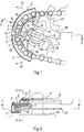
- Fig. 1
- eine schematische Seitenansicht der erfindungsgemäßen Vorrichtung mit zwei Schwenkprofilen in der Ausgangsposition als Schnitt gemäß I-I der Fig. 2,
- Fig. 2
- eine Draufsicht zu Fig. 1,
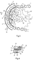
- Fig. 3
- eine Ansicht der Vorrichtung gemäß Fig. 1, jedoch in der Stützposition der Schwenkprofile,
- Fig. 4
- einen Schnitt gemäß IV-IV der Fig. 3,
- Fig. 5
- einen Schnitt gemäß V-V der Fig. 2,
- Fig. 6
- eine etwas vereinfachte Ansicht der Vorrichtung gemäß Fig. 1, jedoch in einer Zwischenposition der Schwenkprofile,
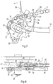
- Fig. 7
- eine schematische Seitenansicht einer anderen Ausführungsform der Vorrichtung mit einem verschwenkbaren Segmentblech in der Ausgangsposition,
- Fig. 8
- eine Draufsicht auf die Vorrichtung gemäß Fig. 7,
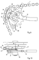
- Fig. 9
- eine Ansicht gemäß Fig. 7 mit in die Stützposition verschwenktem Segmentblech und
- Fig. 10
- eine Draufsicht zu Fig. 9.
- Fig. 1
- 2 shows a schematic side view of the device according to the invention with two swivel profiles in the starting position as a section according to II in FIG. 2,
- Fig. 2
- 2 shows a top view of FIG. 1,
- Fig. 3
- 1, but in the supporting position of the swivel profiles,
- Fig. 4
- 4 shows a section according to IV-IV of FIG. 3,
- Fig. 5
- 2 shows a section according to VV of FIG. 2,
- Fig. 6
- 2 shows a somewhat simplified view of the device according to FIG. 1, but in an intermediate position of the swivel profiles,
- Fig. 7
- 2 shows a schematic side view of another embodiment of the device with a pivotable segment plate in the starting position,
- Fig. 8
- 7 shows a plan view of the device according to FIG. 7,
- Fig. 9
- a view of FIG. 7 with the segment plate pivoted into the supporting position and
- Fig. 10
- 9 shows a top view of FIG. 9.
Die Fig. 1 bis 6 zeigen eine erste Ausführungsform der erfindungsgemäßen Vorrichtung. Wegen der kleinen Verstellwegent der die Stützelemente zum Abstützen der Kette 1 bildenden Schwenkprofile 2, 3 eignet sich diese Ausführungsform für Fahrräder mit Naben-Gangschaltung oder ohne Gangschaltung, bei denen der Durchhang der Kette 1 begrenzt ist. Dies ist der Grund, weshalb die Kette zum Zwecke ihrer Übergabe von einem Kettenrad auf ein Stützelement nur begrenzt vom Kettenrad abhebbar ist. Dieses Abheben besorgen die beiden Schwenkprofile 2, 3, welche durch Verdrehen einer Schwenknocke 4 mit ihren nicht angelenkten Enden radial nach außen verschwenkbar sind gemäß den Pfeilen P1, P2. Die beiden Schwenkprofile 2, 3 sind jeweils mit ihren zur Mitte des Kettenbogens hin orientierten Enden um Schwenkpunkte 5 einer Rahmenplatte 6 verschwenkbar, in welchen kurze Exzenterhebelchen 7 angeschlossen sind, die mit den Schwenkprofilen drehfest verbunden sind. Dadurch wandern die zur Mitte des Kettenbogens hin orientierten Enden der Schwenkprofile 2, 3 bei deren Aufspreizen, wie in Fig. 3 gezeigt, nach innen, wodurch nach dem Freigeben der Kette durch das Zahnrad mehr Kettenlänge für das Spreizen der Kette zur Verfügung steht. Die Rahmenplatte 6 besitzt, wie in Fig. 2 ersichtlich, einen abgewinkelten Befestigungsflansch 8, welcher das Ende des den Lagerschlitz 9 für das Hinterrad enthaltenden Rahmenteils 10 umfaßt und mittels einer Durchgangsschraube 11 mit letzterem verbunden ist. Die beiden Schwenkprofile 2, 3 werden mittels Zugfedern 12, welche an der Rahmenplatte 6 verankert sind, in ihrer Ausgangsposition gehalten, so daß sie nicht ungewollt in Eingriff mit der Kette 1 gelangen.1 to 6 show a first embodiment of the device according to the invention. Because of the small adjustment path of the swivel profiles 2, 3 forming the support elements for supporting the chain 1, this embodiment is suitable for bicycles with hub gear shift or without gear shift, in which the sag of chain 1 is limited. This is the reason why the chain can only be lifted off the sprocket to a limited extent for the purpose of transferring it from a sprocket to a support element. This lifting is provided by the two
Der Schwenknocken 4 sitzt auf einem im Rahmenteil 10 schwenkbar gelagerten Bolzen 13, an dessen anderem Ende ein Schwenkhebel 14 befestigt ist. Der Schwenkhebel 14 untergreift mit einer entsprechenden Biegung den seitlichen Achsstummel 15 des Hinterrads, dessen Nabe 16 lediglich durch eine Umrißlinie angedeutet ist. Auf dem Achsstummel 15 sitzt drehfest das hintere Kettenrad 17, welches über die Kette 1 angetrieben wird.The
Der Schwenkhebel 14 besitzt auf der hinteren Seite des Achsstummels 15 einen nach oben ragenden Dorn 18, welcher bei Betätigung des Schwenkhebels 14 in Richtung des Pfeils P3 gegen den Achsstummels 15 anfährt und diesen folglich aus dem Lagerschlitz 9 ausrückt.The
Infolge der Betätigung des Schwenkhebels 14 wird der Schwenknocken 4 aus seiner waagerechten Position gemäß Fig. 1 in seine vertikale Spreizposition gemäß Fig. 3 gedreht, wobei dessen Drehposition in Fig. 6 bei einem Schwenkwinkel von etwa 45° dargestellt ist. Das bereits vor dem Betätigen des Schwenkhebels 14 gelöste Hinterrad wird während des Verschwenkens des Schwenkhebels 14 zunächst mit Hilfe des Dorns 18 angestoßen und wandert dann zwanglos durch den schräg nach unten verlaufenden Lagerschlitz 9 nach vorne, bis es außer Eingriff mit den Kettengliedern kommt. Gleichzeitig findet die Kette 1 ihren Halt an den nach innen gegen das Zahnrad 17 verlaufenden Stützflächen 19 der Schwenkprofile, wie in den Fig. 3 und 6 sowie vergrößert in Fig. 4 dargestellt.As a result of the actuation of the
Die beiden Stützprofile 2, 3 umfassen etwa U-förmig das Kettenrad 17 im Bereich der Kette 1, wie in Fig. 2 verdeutlicht ist. Dort erkennt man auch den Schwenkpunkt 5 des Stützprofils 2 in der Rahmenplatte 6.The two
Zum Verschwenken der Stützprofile 2, 3 wirkt der Schwenknocken 4 mit diesem auf beiden Seiten zugeordneten, nach innen ragenden Vorsprüngen 20 der Stützprofile 2, 3 zusammen. Deren dem Schwenknocken 4 benachbarte Flanken werden mittels der Zugfedern 12 stets in Anlage gehalten und beim Verschwenken des Schwenknockens 4 entsprechend auseinander bewegt, bis die in Fig. 3 dargestellte maximale Schwenklage erreicht ist.For pivoting the support profiles 2, 3, the
Die Fig. 1, 3 und 6 unterscheiden sich im wesentlichen nur durch die unterschiedlichen Schwenklage des Schwenkbolzens 4. Fig. 6 zeigt eine vereinfachte Darstellung insofern, als dort die Rahmenplatte 6 der besseren Übersicht wegen weggelassen ist.1, 3 and 6 differ essentially only in the different pivoting position of the
Der in Fig. 4 dargestellte Ausschnitt gemäß IV-IV der Fig. 3 zeigt - nach dem Ausrücken des Zahnrads 17 - ein gegen die beiden Stützflächen 19 mit den seitlichen Zuggliedern 21 anliegendes Kettenglied, dessen Zugglieder 21 über einen Steg 22 miteinander verbunden sind.The section shown in FIG. 4 according to IV-IV of FIG. 3 shows - after the
Die Fig. 7 bis 10 zeigen eine weitere Ausführungsform der Erfindung, wobei das Rahmenteil 10 mit dem Längsschlitz 9 zur Aufnahme der Radachse 23 des Hinterrads an seinem unteren Ende ein Lagerauge 33 zum Anlenken eines Hebels zum Strammen der Kette bei einer Ketten-Gangschaltung aufweist. Da bei dieser Ausführungsform genügend Kettenlänge für die Übergabe der Kette 1 an ein als Segmentblech 24 ausgebildetes Stützelement zur Verfügung steht, genügt dessen einfache Schwenklagerung um einen Anlenkpunkt 25 am Rahmen 10. Das Segmentblech 24 besitzt an seinem Umfang eine Stützkante 26 mit einem radial vorspringenden Zahn 27 am oberen Ende. Bewegt man das Segmentblech 24 mittels des daran befestigten Fingerhebels 28 im Gegenuhrzeigersinn gemäß Pfeil P4, so untergreift die Stützkante 26 die Kette 1, indem sie diese aus der Verzahnung des Zahnrads 17 abhebt, wie in Fig. 9 für den maximalen Schwenkweg dargestellt. Während das Segmentblech 24 in der Ausgangsposition gemäß Fig. 7 mit seiner unteren Flanke 29 auf dem Achsstummel 15 aufliegt, trifft dies in der Endposition gemäß Fig. 9 für dessen andere Flanke 30 zu.7 to 10 show a further embodiment of the invention, wherein the
Wie man in Fig. 8 erkennen kann, ist der Anlenkpunkt 25 des Segmentblechs 24 in einer das Rahmenteil 10 in dessen hinteren Bereich umfassenden Befestigungslasche 31 gelagert, welche mittels zweier Schrauben 32 im Rahmenteil 10 befestigt ist. Der Zahn 27 der Stützkante 26 erleichtert das Verschwenken des Segmentblechs 24 in Richtung des Pfeiles P4, indem die Kette 1 nach dem Eingreifen des Zahns 27 in diese nach links gemäß Pfeil P5 bewegt wird. Dabei wird mittels des Zahns 27 das Segmentblech 24 automatisch mitgenommen, bis der Zahn 27 seine in Fig. 9 gezeigte Endposition erreicht hat, in welcher er sich mit seiner gerundeten Flanke gegen einen Kettensteg 22 abstützt.As can be seen in FIG. 8, the
Wie in den Fig. 8 und 10 ersichtlich ist das Segmentblech 24 längs seines Umfangs zunächst um 90° axial nach innen, dann wieder um 90° radial nach außen umgebogen, so daß die dadurch gebildete Stützkante 26 genau in der Ebene des äußeren Zahnkranzes 17 der Kettenschaltung zwischen diesen und die Kette eingreift, so daß letztlich die Stützkante 26 etwa mittig an der Innenseite der Kettenstege 22 angreift.As can be seen in FIGS. 8 and 10, the
Claims (16)
dadurch gekennzeichnet,
daß die Führung ein in der Kettenebene verschwenkbares Stützelement umfaßt, welches aus einer von der Kette (1) entfernten Ausgangsposition in eine die Kette (1) von innen greifende Stützposition verschwenkbar ist.Device for disengaging a bicycle chain and transferring it from a sprocket (17) of the rear wheel to a guide connected to the bicycle frame for supporting the chain (1) in the extended position in order to remove the rear wheel,
characterized,
that the guide comprises a support element which can be pivoted in the chain plane and which can be pivoted from a starting position removed from the chain (1) into a support position which engages the chain (1) from the inside.
dadurch gekennzeichnet,
daß das Stützelement wenigstens eine in Richtung der Kette (1) bogenförmige Stützkante (26) aufweist, welche in der Stützposition an den Stegen (22) der Kettenglieder anliegt.Device according to claim 1,
characterized,
that the support element has at least one support edge (26) which is curved in the direction of the chain (1) and which, in the support position, bears against the webs (22) of the chain links.
dadurch gekennzeichnet,
daß das Stützelement wenigstens eine in Richtung der Kette (1) bogenförmige Stützfläche (19) aufweist, welche in der Stützposition an den Zuggliedern (21) einer Kettenseite anliegt.Device according to claim 1,
characterized,
that the support element has at least one arcuate support surface (19) in the direction of the chain (1) which, in the support position, rests on the tension members (21) of one side of the chain.
dadurch gekennzeichnet,
daß das Stützelement benachbart der Hinterradachse an dem deren Lagerschlitz (9) bildenden Rahmenteil (10) angelenkt ist, derart, daß es um den Anlenkpunkt (25) aus seiner Ausgangsposition von vorne in seine Stützposition nach hinten verschwenkbar ist.Device according to claim 2,
characterized,
that the support element is articulated adjacent to the rear wheel axle on the frame part (10) forming its bearing slot (9), in such a way that it can be pivoted about the articulation point (25) from its initial position from the front to its support position to the rear.
dadurch gekennzeichnet,
daß die Stützkante (26) wenigstens einen radial nach außen vorspringenden in die Kettenglieder eingreifenden Zahn (27) aufweist.Device according to claim 2,
characterized,
that the support edge (26) has at least one radially outwardly projecting tooth (27) engaging in the chain links.
dadurch gekennzeichnet,
daß die Stützkante (26) an einem Segmentblech (24) ausgebildet ist, welches an seinem Umfang axial nach innen gebogen ist und an seiner Innenkante einen radial nach außen gebogenen Rand in Form der Stützkante (26) aufweist.Device according to claim 2,
characterized,
that the support edge (26) is formed on a segment plate (24) which is bent axially inward on its circumference and has a radially outwardly bent edge in the form of the support edge (26) on its inner edge.
dadurch gekennzeichnet,
daß das Segmentblech (24) an einer an der Innenseite des dem äußersten Kettenrad (17) benachbarten Rahmenteils (10) angebrachten Befestigungslasche (31) angelenkt ist.Apparatus according to claim 6,
characterized,
that the segment plate (24) on one on the inside of the outermost sprocket (17) adjacent frame part (10) attached mounting bracket (31) is articulated.
dadurch gekennzeichnet,
daß am Segmentblech (24) ein axial nach außen vorspringender Fingerhebel (28) zu dessen Verschwenken vorgesehen ist.Apparatus according to claim 6,
characterized,
that an axially outwardly projecting finger lever (28) is provided on the segment plate (24) for pivoting it.
dadurch gekennzeichnet,
daß das Stützelement zwei Stützflächen (19) für die einander gegenüberliegenden Zugglieder (21) der Kette (1) aufweist, wobei die Stützflächen (19) als gegen den Zahnkranz (17) gerichtete Stege (22) eines die Kette (1) von drei Seiten umschließenden U-förmigen Schwenkprofils (2, 3) ausgebildet sind.Device according to claim 3,
characterized,
that the support element has two support surfaces (19) for the opposing tension members (21) of the chain (1), the support surfaces (19) as webs (22) directed against the ring gear (17) one of the chain (1) from three sides enclosing U-shaped pivot profile (2, 3) are formed.
dadurch gekennzeichnet,
daß das Schwenkprofil (2, 3) bogenförmig ausgebildet ist und an einem Ende um einen in mittlerer Höhe des Kettenbogens hinter der Kette (1) befindlichen rahmenfesten Schwenkpunkt (5) verschwenkbar ist, derart, daß die ausgeschwenkten Stützflächen (19) im Bereich des anderen Endes des Schwenkprofils (2, 3) die Kette (1) nach innen abstützen.Device according to claim 9,
characterized,
that the swivel profile (2, 3) is arch-shaped and at one end can be pivoted about a frame-fixed pivot point (5) located in the middle of the chain arch behind the chain (1), in such a way that the pivoted out support surfaces (19) in the area of the other End of Support the chain (1) inwards on the swivel profile (2, 3).
dadurch gekennzeichnet,
daß zwei Schwenkprofile (2, 3) etwa symmetrisch zur Horizontalen durch die mittlere Höhe des Kettenbogens angeordnet sind, welche durch einen gemeinsamen Schwenkantrieb betätigbar sind.Apparatus according to claim 10,
characterized,
that two swivel profiles (2, 3) are arranged approximately symmetrically to the horizontal through the average height of the chain link, which can be actuated by a common swivel drive.
dadurch gekennzeichnet,
daß der Schwenkantrieb einen mittels eines Schwenkhebels (14) betätigbaren Schwenknocken (4) umfaßt, welcher mit Vorsprüngen (20) an den einander zugewandten Enden der Schwenkprofile (2, 3) zusammenwirkt, derart, daß die Schwenkprofile (2, 3) mit ihren gegenüberliegenden Enden von innen gegen die Kette (1) aufgespreizt werden.Device according to claim 11,
characterized,
that the swivel drive comprises a swivel cam (4) which can be actuated by means of a swivel lever (14) and which cooperates with projections (20) on the mutually facing ends of the swivel profiles (2, 3), such that the swivel profiles (2, 3) with their opposite ones Spread the ends from the inside against the chain (1).
dadurch gekennzeichnet,
daß der den Lagerschlitz (9) bildende Rahmenteil (10) nach hinten mittels einer die Schwenkpunkte (5) für die Schwenkprofile aufnehmenden Rahmenplatte (6) verlängert ist.Device according to claim 12,
characterized,
that the frame part (10) forming the bearing slot (9) is extended towards the rear by means of a frame plate (6) receiving the pivot points (5) for the pivot profiles.
dadurch gekennzeichnet,
daß die Schwenkprofile (2, 3) derart exzentrisch an den Schwenkpunkten (5) der Rahmenplatte angelenkt sind, daß sich die einander zugewandten Enden der Schwenkprofile (2, 3) bei deren Aufspreizen zur Kette (1) hin bewegen.Device according to claim 13,
characterized,
that the pivot profiles (2, 3) are articulated so eccentrically to the pivot points (5) of the frame plate that the mutually facing ends of the pivot profiles (2, 3) move towards the chain (1) when they are spread apart.
dadurch gekennzeichnet,
daß der Schwenkhebel (14) von unten um den zugeordneten Achsstummel (15) gebogen ist, welcher die der Ausgangsposition entsprechende obere Anschlagstellung bildet.Device according to claim 12,
characterized,
that the pivot lever (14) is bent from below around the associated stub shaft (15), which forms the upper stop position corresponding to the starting position.
dadurch gekennzeichnet,
daß der Schwenkhebel (14) dicht hinter dem Achsstummel (15) einen nach oben gerichteten Dorn (18) zum Ausrücken des Achsstummels (15) aus dem Lagerschlitz (9) aufweist.Device according to claim 15,
characterized,
that the swivel lever (14) close behind the stub axle (15) has an upwardly directed mandrel (18) for disengaging the stub axle (15) from the bearing slot (9).
Applications Claiming Priority (2)
| Application Number | Priority Date | Filing Date | Title |
|---|---|---|---|
| DE19620026 | 1996-05-17 | ||
| DE19620026A DE19620026C1 (en) | 1996-05-17 | 1996-05-17 | Uncoupling device for cycle chain |
Publications (3)
| Publication Number | Publication Date |
|---|---|
| EP0807569A2 true EP0807569A2 (en) | 1997-11-19 |
| EP0807569A3 EP0807569A3 (en) | 1998-12-09 |
| EP0807569B1 EP0807569B1 (en) | 2003-08-20 |
Family
ID=7794639
Family Applications (1)
| Application Number | Title | Priority Date | Filing Date |
|---|---|---|---|
| EP97103188A Expired - Lifetime EP0807569B1 (en) | 1996-05-17 | 1997-02-27 | Device for disengaging a bicycle chain |
Country Status (3)
| Country | Link |
|---|---|
| EP (1) | EP0807569B1 (en) |
| AT (1) | ATE247577T1 (en) |
| DE (2) | DE19620026C1 (en) |
Cited By (1)
| Publication number | Priority date | Publication date | Assignee | Title |
|---|---|---|---|---|
| US20230079035A1 (en) * | 2021-09-15 | 2023-03-16 | TILT Industries LLC | Chain separator for manual bike training |
Families Citing this family (1)
| Publication number | Priority date | Publication date | Assignee | Title |
|---|---|---|---|---|
| DE102005006682B3 (en) * | 2005-02-15 | 2006-08-17 | Ulrich Rombach | Bicycle driving chain supporting device e.g. for bicycles with derailleur, has sequential gear changer and chain for rear wheel and U-shaped retainer insertable into suitable recess of gear changer |
Family Cites Families (7)
| Publication number | Priority date | Publication date | Assignee | Title |
|---|---|---|---|---|
| DE1118560B (en) * | 1958-05-16 | 1961-11-30 | Winkelhofer & Soehne Joh | Chain wheel drive with a chain guide |
| FR2172610A5 (en) * | 1972-02-17 | 1973-09-28 | Micmo | |
| CH569204A5 (en) * | 1972-09-15 | 1975-11-14 | Kropf Walter | |
| US3862487A (en) * | 1973-04-30 | 1975-01-28 | Gundy Kenneth Warren Van | Chain positioner for 10-speed bicycle |
| CH607823A5 (en) * | 1975-11-07 | 1978-11-15 | Tullio Campagnolo | Device enabling the bicycle transmission chain to be disengaged from the sprocket wheels of the free wheel |
| US4167125A (en) * | 1977-04-20 | 1979-09-11 | Eberhard Hedrich | Rear-wheel mounting for bicycle |
| FR2451855A1 (en) * | 1979-03-20 | 1980-10-17 | Soulisse Jean | CHAIN REST |
-
1996
- 1996-05-17 DE DE19620026A patent/DE19620026C1/en not_active Expired - Fee Related
-
1997
- 1997-02-27 DE DE59710598T patent/DE59710598D1/en not_active Expired - Fee Related
- 1997-02-27 EP EP97103188A patent/EP0807569B1/en not_active Expired - Lifetime
- 1997-02-27 AT AT97103188T patent/ATE247577T1/en not_active IP Right Cessation
Cited By (3)
| Publication number | Priority date | Publication date | Assignee | Title |
|---|---|---|---|---|
| US20230079035A1 (en) * | 2021-09-15 | 2023-03-16 | TILT Industries LLC | Chain separator for manual bike training |
| GB2612188A (en) * | 2021-09-15 | 2023-04-26 | Tilt Ind Llc | Chain separator systems and methods |
| GB2612188B (en) * | 2021-09-15 | 2025-05-28 | Tilt Ind Llc | Chain separator systems and methods |
Also Published As
| Publication number | Publication date |
|---|---|
| DE59710598D1 (en) | 2003-09-25 |
| EP0807569A3 (en) | 1998-12-09 |
| DE19620026C1 (en) | 1997-07-24 |
| ATE247577T1 (en) | 2003-09-15 |
| EP0807569B1 (en) | 2003-08-20 |
Similar Documents
| Publication | Publication Date | Title |
|---|---|---|
| DE3308538C2 (en) | ||
| DE2844122C2 (en) | Front derailleur for a bicycle | |
| DE69016320T2 (en) | Sprocket set for bicycle. | |
| DE69731523T2 (en) | Two-wheel hub assembly device | |
| DE20206816U1 (en) | scooter | |
| EP0341425A2 (en) | Device for collecting folded printed sheets | |
| DE3202382C2 (en) | Reversible accumulation conveyor | |
| EP0800977A2 (en) | Transportation device with motor driven stair climbing device | |
| DE3123810C2 (en) | Conveying and holding device for a toothed, curved lead-up strand of a continuous casting machine | |
| DE19607837A1 (en) | Decorating objects or containers travelling along conveyor belt | |
| DE2933362C2 (en) | ||
| DE10156992A1 (en) | Escalator step, with a step surface, is held in place at the continuous drive chain by side holding units, incorporating a holding spring as a rapid release coupling which can be dismantled in any position of the escalator | |
| EP0807569B1 (en) | Device for disengaging a bicycle chain | |
| DE69610140T2 (en) | Suspension device for bicycles | |
| EP0129089B1 (en) | Apparatus for transferring coiler cans | |
| EP0512391B1 (en) | Shifting device for filter plates in a filter press | |
| DE3722284A1 (en) | FEEDING DEVICE, IN PARTICULAR FOR CAN CASES | |
| DE3130314C2 (en) | ||
| DE1761754A1 (en) | Printing press | |
| DE3013854A1 (en) | CHAIN GEAR WITH AUTOMATIC ROPE LENGTH COMPENSATION | |
| DE19642130A1 (en) | Device for the delivery of printed products | |
| DE920132C (en) | Device for the correct sheet transfer by means of gripper chains on printing machines | |
| EP0970599B1 (en) | Rotobaler | |
| EP0732294B1 (en) | Buckle fold machine | |
| DE4101882C2 (en) | Adjustment fitting for vehicle seats, in particular motor vehicle seats |
Legal Events
| Date | Code | Title | Description |
|---|---|---|---|
| PUAI | Public reference made under article 153(3) epc to a published international application that has entered the european phase |
Free format text: ORIGINAL CODE: 0009012 |
|
| AK | Designated contracting states |
Kind code of ref document: A2 Designated state(s): AT BE CH DE DK ES FI FR GB IE IT LI MC NL SE |
|
| PUAL | Search report despatched |
Free format text: ORIGINAL CODE: 0009013 |
|
| AK | Designated contracting states |
Kind code of ref document: A3 Designated state(s): AT BE CH DE DK ES FI FR GB IE IT LI MC NL SE |
|
| 17P | Request for examination filed |
Effective date: 19990312 |
|
| 17Q | First examination report despatched |
Effective date: 20020906 |
|
| GRAH | Despatch of communication of intention to grant a patent |
Free format text: ORIGINAL CODE: EPIDOS IGRA |
|
| GRAS | Grant fee paid |
Free format text: ORIGINAL CODE: EPIDOSNIGR3 |
|
| GRAA | (expected) grant |
Free format text: ORIGINAL CODE: 0009210 |
|
| AK | Designated contracting states |
Designated state(s): AT BE CH DE DK ES FI FR GB IE IT LI MC NL SE |
|
| PG25 | Lapsed in a contracting state [announced via postgrant information from national office to epo] |
Ref country code: NL Free format text: LAPSE BECAUSE OF FAILURE TO SUBMIT A TRANSLATION OF THE DESCRIPTION OR TO PAY THE FEE WITHIN THE PRESCRIBED TIME-LIMIT Effective date: 20030820 Ref country code: IT Free format text: LAPSE BECAUSE OF FAILURE TO SUBMIT A TRANSLATION OF THE DESCRIPTION OR TO PAY THE FEE WITHIN THE PRESCRIBED TIME-LIMIT;WARNING: LAPSES OF ITALIAN PATENTS WITH EFFECTIVE DATE BEFORE 2007 MAY HAVE OCCURRED AT ANY TIME BEFORE 2007. THE CORRECT EFFECTIVE DATE MAY BE DIFFERENT FROM THE ONE RECORDED. Effective date: 20030820 Ref country code: IE Free format text: LAPSE BECAUSE OF FAILURE TO SUBMIT A TRANSLATION OF THE DESCRIPTION OR TO PAY THE FEE WITHIN THE PRESCRIBED TIME-LIMIT Effective date: 20030820 Ref country code: GB Free format text: LAPSE BECAUSE OF FAILURE TO SUBMIT A TRANSLATION OF THE DESCRIPTION OR TO PAY THE FEE WITHIN THE PRESCRIBED TIME-LIMIT Effective date: 20030820 Ref country code: FR Free format text: LAPSE BECAUSE OF FAILURE TO SUBMIT A TRANSLATION OF THE DESCRIPTION OR TO PAY THE FEE WITHIN THE PRESCRIBED TIME-LIMIT Effective date: 20030820 Ref country code: FI Free format text: LAPSE BECAUSE OF FAILURE TO SUBMIT A TRANSLATION OF THE DESCRIPTION OR TO PAY THE FEE WITHIN THE PRESCRIBED TIME-LIMIT Effective date: 20030820 |
|
| REG | Reference to a national code |
Ref country code: GB Ref legal event code: FG4D Free format text: NOT ENGLISH |
|
| REG | Reference to a national code |
Ref country code: CH Ref legal event code: EP |
|
| REG | Reference to a national code |
Ref country code: IE Ref legal event code: FG4D Free format text: GERMAN |
|
| REF | Corresponds to: |
Ref document number: 59710598 Country of ref document: DE Date of ref document: 20030925 Kind code of ref document: P |
|
| PG25 | Lapsed in a contracting state [announced via postgrant information from national office to epo] |
Ref country code: SE Free format text: LAPSE BECAUSE OF FAILURE TO SUBMIT A TRANSLATION OF THE DESCRIPTION OR TO PAY THE FEE WITHIN THE PRESCRIBED TIME-LIMIT Effective date: 20031120 Ref country code: DK Free format text: LAPSE BECAUSE OF FAILURE TO SUBMIT A TRANSLATION OF THE DESCRIPTION OR TO PAY THE FEE WITHIN THE PRESCRIBED TIME-LIMIT Effective date: 20031120 |
|
| PG25 | Lapsed in a contracting state [announced via postgrant information from national office to epo] |
Ref country code: ES Free format text: LAPSE BECAUSE OF FAILURE TO SUBMIT A TRANSLATION OF THE DESCRIPTION OR TO PAY THE FEE WITHIN THE PRESCRIBED TIME-LIMIT Effective date: 20031201 |
|
| NLV1 | Nl: lapsed or annulled due to failure to fulfill the requirements of art. 29p and 29m of the patents act | ||
| GBV | Gb: ep patent (uk) treated as always having been void in accordance with gb section 77(7)/1977 [no translation filed] |
Effective date: 20030820 |
|
| PG25 | Lapsed in a contracting state [announced via postgrant information from national office to epo] |
Ref country code: AT Free format text: LAPSE BECAUSE OF NON-PAYMENT OF DUE FEES Effective date: 20040227 |
|
| PG25 | Lapsed in a contracting state [announced via postgrant information from national office to epo] |
Ref country code: MC Free format text: LAPSE BECAUSE OF NON-PAYMENT OF DUE FEES Effective date: 20040228 Ref country code: BE Free format text: LAPSE BECAUSE OF NON-PAYMENT OF DUE FEES Effective date: 20040228 |
|
| PG25 | Lapsed in a contracting state [announced via postgrant information from national office to epo] |
Ref country code: LI Free format text: LAPSE BECAUSE OF NON-PAYMENT OF DUE FEES Effective date: 20040229 Ref country code: CH Free format text: LAPSE BECAUSE OF NON-PAYMENT OF DUE FEES Effective date: 20040229 |
|
| REG | Reference to a national code |
Ref country code: IE Ref legal event code: FD4D |
|
| PGFP | Annual fee paid to national office [announced via postgrant information from national office to epo] |
Ref country code: DE Payment date: 20040427 Year of fee payment: 8 |
|
| PLBE | No opposition filed within time limit |
Free format text: ORIGINAL CODE: 0009261 |
|
| STAA | Information on the status of an ep patent application or granted ep patent |
Free format text: STATUS: NO OPPOSITION FILED WITHIN TIME LIMIT |
|
| 26N | No opposition filed |
Effective date: 20040524 |
|
| BERE | Be: lapsed |
Owner name: MARKETING & PROMOTION WUNDERLICH G.M.B.H. *MP Effective date: 20040228 |
|
| EN | Fr: translation not filed | ||
| REG | Reference to a national code |
Ref country code: CH Ref legal event code: PL |
|
| PG25 | Lapsed in a contracting state [announced via postgrant information from national office to epo] |
Ref country code: DE Free format text: LAPSE BECAUSE OF NON-PAYMENT OF DUE FEES Effective date: 20050901 |