EP0807578B1 - Steuerung der Drehbewegung eines Raumfahrzeuges - Google Patents
Steuerung der Drehbewegung eines Raumfahrzeuges Download PDFInfo
- Publication number
- EP0807578B1 EP0807578B1 EP97303125A EP97303125A EP0807578B1 EP 0807578 B1 EP0807578 B1 EP 0807578B1 EP 97303125 A EP97303125 A EP 97303125A EP 97303125 A EP97303125 A EP 97303125A EP 0807578 B1 EP0807578 B1 EP 0807578B1
- Authority
- EP
- European Patent Office
- Prior art keywords
- spacecraft
- axis
- sun
- rotation
- predetermined
- Prior art date
- Legal status (The legal status is an assumption and is not a legal conclusion. Google has not performed a legal analysis and makes no representation as to the accuracy of the status listed.)
- Expired - Lifetime
Links
Images


Classifications
-
- B—PERFORMING OPERATIONS; TRANSPORTING
- B64—AIRCRAFT; AVIATION; COSMONAUTICS
- B64G—COSMONAUTICS; VEHICLES OR EQUIPMENT THEREFOR
- B64G1/00—Cosmonautic vehicles
- B64G1/22—Parts of, or equipment specially adapted for fitting in or to, cosmonautic vehicles
- B64G1/24—Guiding or controlling apparatus, e.g. for attitude control
- B64G1/36—Guiding or controlling apparatus, e.g. for attitude control using sensors, e.g. sun-sensors, horizon sensors
- B64G1/365—Guiding or controlling apparatus, e.g. for attitude control using sensors, e.g. sun-sensors, horizon sensors using horizon or Earth sensors
-
- B—PERFORMING OPERATIONS; TRANSPORTING
- B64—AIRCRAFT; AVIATION; COSMONAUTICS
- B64G—COSMONAUTICS; VEHICLES OR EQUIPMENT THEREFOR
- B64G1/00—Cosmonautic vehicles
- B64G1/22—Parts of, or equipment specially adapted for fitting in or to, cosmonautic vehicles
- B64G1/24—Guiding or controlling apparatus, e.g. for attitude control
- B64G1/26—Guiding or controlling apparatus, e.g. for attitude control using jets
-
- B—PERFORMING OPERATIONS; TRANSPORTING
- B64—AIRCRAFT; AVIATION; COSMONAUTICS
- B64G—COSMONAUTICS; VEHICLES OR EQUIPMENT THEREFOR
- B64G1/00—Cosmonautic vehicles
- B64G1/22—Parts of, or equipment specially adapted for fitting in or to, cosmonautic vehicles
- B64G1/24—Guiding or controlling apparatus, e.g. for attitude control
- B64G1/36—Guiding or controlling apparatus, e.g. for attitude control using sensors, e.g. sun-sensors, horizon sensors
- B64G1/363—Guiding or controlling apparatus, e.g. for attitude control using sensors, e.g. sun-sensors, horizon sensors using sun sensors
-
- B—PERFORMING OPERATIONS; TRANSPORTING
- B64—AIRCRAFT; AVIATION; COSMONAUTICS
- B64G—COSMONAUTICS; VEHICLES OR EQUIPMENT THEREFOR
- B64G1/00—Cosmonautic vehicles
- B64G1/22—Parts of, or equipment specially adapted for fitting in or to, cosmonautic vehicles
- B64G1/24—Guiding or controlling apparatus, e.g. for attitude control
- B64G1/36—Guiding or controlling apparatus, e.g. for attitude control using sensors, e.g. sun-sensors, horizon sensors
- B64G1/369—Guiding or controlling apparatus, e.g. for attitude control using sensors, e.g. sun-sensors, horizon sensors using gyroscopes as attitude sensors
Definitions
- This invention relates to apparatus for the control of spacecraft, and more particularly to a technique for controlling the rotation of the spacecraft.
- the invention arose when considering problems associated with the control of a geostationary satellite when it is in its so-called "survival mode", which will be explained later. However the invention could possibly be of value more generally in connection with spacecraft control.
- FIG. 1 shows a geostationary satellite in very schematic form.
- An earth sensor 1 e.g. a camera for viewing the earth, faces in the z direction and pairs of thrusters X+, X-; Y+, Y- and Z+, Z- adjust rotation of the satellite about respective axes.
- Sun sensors 2 (only one shown) on opposite sides of the satellite provide output signals indicating the direction of the sun relative to the x, y and z axes.
- the z axis is always aligned with the earth, the y axis is parallel with the earth's axis and the x axis makes a tangent with the geostationary orbit.
- the field of view of the earth sensor 1 is usually quite narrow since the earth subtends only a small angle at the satellite. For this reason, if the earth is lost from the field of view, it can be difficult to adjust the attitude of the satellite to retrieve it. Unless remedial action is taken, the satellite will quickly fail because the reference direction from which the solar panels 3 are steered to face the sun has been lost and the supply of adequate electrical power with therefore discontinue.
- Some satellites have a system which puts the satellite into a "survival" mode if the earth is lost from the field of view of the earth sensor 1.
- this survival mode signals from sun sensors 2 are used to control thrusts Y+, Y-and Z+, Z- so as to align the satellite's x axis with the direction of the sun as shown in Figure 3.
- the x axis now provides a new reference direction making it possible to control the satellite's solar panels 3 so that they face the sun, thereby providing the power necessary for the satellite to survive.
- intervention can be taken from the ground to retrieve the earth into the field of view of the earth sensor 1.
- the time that the survival mode could be maintained would be limited if there were no way of controlling the rate of rotation about the x axis.
- the conventional way to control rotation about the x axis is to use a gyroscope to sense the rotation and to operate thrusters X+ and X- to control it, as in prior art document EP-A-0603058.
- a gyroscope needs to be reliable over the entire life of the spacecraft and gyroscopes having this degree of long-term reliability are costly.
- the invention arose when considering possible solutions to this problem.
- EP0790542 A (D1) describes a method of controlling the attitude of a three-axis stabilised, earth oriented bias momentum spacecraft.
- the controller of D1 relies on a decoupling controller and on axis-related PID controllers.
- EP0794122A (D2) describes a satellite ground loop controller which interfaces with the satellite ground station to permit automatic continuation of attitude control should the momentum wheel/reaction wheel system fail.
- the x axis When the satellite is in its survival mode, the x axis will gradually drift out of alignment with the direction of the sun.
- the thruster Y+ When the direction of the sun makes an angle of - ⁇ with the x y plane the thruster Y+ is fired causing reversal of the drift until the direction of the sun makes an angle of + ⁇ with the x y plane whereupon the thruster Y- is fired.
- This process is repeated, resulting in oscillation of the satellite about the y axis relative to the direction of the sun as shown at A in Figure 4.
- a similar oscillation occurs about the z axis caused by alternate firing of thrusters Z+ and Z- when the direction of the sun drifts to an angle of - ⁇ or + ⁇ .
- the inventors have realised that the characteristics (more particularly the first and second deviates with respect to time) of the relative movement between the direction of the sun and the x axis of the satellite (as depicted by the lines A, B, C, D for example) can be used to measure rotation of the satellite about the x axis.
- an apparatus for controlling the rotation of a spacecraft about a predetermiend axis (x) comprising sensing means for inspecting characteristics of relative movement between the predetermined axis (x) of the spacecraft and the direction of the sun; rotation indicating means for deriving from those characteristics an indication of rotation of the spacecraft about the predetermined (x) axis; and rotation control means for using said indication so as to control the rotation of the spacecraft about said predetermined axis.
- a method of controlling the rotation of a spacecraft about a predetermined axis (x) comprising the steps of: sensing and inspecting characteristics of relative movement between the predetermined axis (x) of the spacecraft and the direction of the sun; deriving from those characteristics an indication of rotation of the spacecraft about the predetermined (x) axis; and using said indication to control the rotation of the spacecraft about said predetermined axis.
- the measurements as described above can be made more accurately in situations as shown at A or B for example where variation of angle ⁇ is a maximum and where the number of thruster firings is a minimum. It is important that the number of thruster firings be minimised because it is impossible to take measurements of derivatives and second derivatives during a period d 1 whilst a thruster is firing and during a short period d 2 immediately after such operation when the satellite is subject to vibration. Thus there are periods, shown by the cross-hatched areas of Figure 4, when measurements are inhibited.
- the characteristic shape is more predictable because it is less subject to changes arising from inaccuracies in measurement of the inertia of the spacecraft. It is therefore preferable to arrange for the thrusters Y-, Y+ and Z-, Z+ to be controlled so as to produce such an angular offset.
- the rotation of the satellite about the direction of the sun can be derived mathematically as follows.
- the equations governing the movements of the sun as viewed by the satellite's sun sensors are: where I is the moment of inertia of the spacecraft about its x axis and is the rotation vector of the sun; and where is the vector defining the sun's direction.
- Figure 7 shows the behaviour observed when is aligned with the maximum or minimum principal axis of inertia.
- the motion is more complex due to the nutation of vector but it shows that it is possible to identify the sign of by observing the curvature of the movement and this principle makes it possible to avoid the need for a gyroscope in the survival mode.
- the sun In order to measure speed of rotation by observing the movement of the sun, it is preferable that the sun should be as far removed as possible from the speed vector. To achieve that the limit cycle must be wide. This is achieved by adaptive control.
- the controllers on both Y and Z axis are simple uncoupled controllers with torque estimator. The torque estimation is used to continuously modify the controller parameters in order to achieve a limit cycle as shown in Figure 4A or B.
- the movement of the sun must have a low sensitivity to the uncertainties on the satellite inertia matrix.
- the minimum principal of axis of inertia is close to the Y axis and the two others in the close to the X/Z plane.
- the nutation motion is strongly driven by the minimum axis of inertia since the two others are generally close due to the "pen shape" of the spacecraft.
- the main uncertainty of the inertia matrix is to know where is the minimum axis of inertia with respect to the Y axis.
- a small bending of the solar array will move the principal axis away from Y by about the same angle as the bending angle.
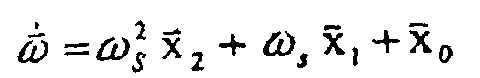
- Equation 3 is then expressed in the following form:
- this shows two sun sensors 2 each having four photodiodes 2A.
- the outputs of the photodiodes are fed to a processor 4 which produces outputs 5 and 6 indicating the angle ⁇ XZ and ⁇ XY between the x axis and the projection of the sun's vector onto the x z and x y planes respectively.
- These are the angles through which the satellite needs to be turned about the y and z axes to align the x axis with the sun.
- the angle represented by the signal on line 5 is added at 7 to an offset angle typically of ten degrees and the resulting signal on line 8 is applied to a controller 9 which controls the -Z and +Z thrusters.
- An independent controller 10, controlling thrusters -Y and +Y, is identical to controller 9 and will therefore not be described.
- Controller 9 comprises an estimator 9A based on LQG controllers.
- the equation of the estimator is: where ⁇ , ⁇ , T represent angle, rate and external torque respectively, these symbols being shown with a ⁇ to denote their estimated values.
- T a is the torque applied by the thrusters
- T is the external torque applied on the z axis
- I is the satellite inertia on the z axis.
- the two first parts of the right-hand side of the equation represent the model prediction, the first being the prediction without control and the second the impact of the thrusters control torque.
- the third part of the equation represents the estimator updating based on a comparison between the angle prediction ⁇ and and the measurement ⁇ .
- the estimated values of ⁇ and, ⁇ andand T and are passed from 9A to 9B where they are used at to calculate the torque to be applied by the thrusters. This is done by simple multiplication by value K c .
- An adaptive controller 9D serves to modify slowly all the control parameters: K e , K c , T th as a function of T and (which it receives from 9A) in order to achieve the limit cycle B of Figure 4.
- the rate estimator gives accurate estimation and the rate around the sun direction is reduced. As the rate is reduced, the disturbance torque reduces also (since they are mainly due to gyroscopic coupling terms) and the adaptive control continues to adapt the parameters to this reduced rate. At the end the limit cycle tends to the limit cycle of Figure A with low rates and a low consumption.
Landscapes
- Engineering & Computer Science (AREA)
- Remote Sensing (AREA)
- Chemical & Material Sciences (AREA)
- Combustion & Propulsion (AREA)
- Radar, Positioning & Navigation (AREA)
- Aviation & Aerospace Engineering (AREA)
- Life Sciences & Earth Sciences (AREA)
- Environmental & Geological Engineering (AREA)
- General Life Sciences & Earth Sciences (AREA)
- Geochemistry & Mineralogy (AREA)
- Geology (AREA)
- Control Of Position, Course, Altitude, Or Attitude Of Moving Bodies (AREA)
- Navigation (AREA)
Claims (8)
- Vorrichtung zur Steuerung der Drehbewegung eines Raumfahrzeuges um eine vorbestimmte Achse (x), welche die folgenden Teile umfasst: Sensormittel (2) zur Inspektion der Charakteristiken einer Relativbewegung zwischen der vorbestimmten Achse (x) des Raumfahrzeuges und der Richtung der Sonne; Drehanzeigemittel (11) zur Ableitung aus jenen Charakteristiken einer Anzeige der Drehung des Raumfahrzeuges um die vorbestimmte (x)-Achse; und Drehsteuermittel (12) zur Benutzung der Anzeige derart, dass die Drehung des Raumfahrzeuges um die vorbestimmte Achse gesteuert wird.
- Vorrichtung nach Anspruch 1, bei welcher die Sensormittel (2) einen Sonnensensor aufweisen, dessen Ausgang auf die Richtung der Sonne relativ zur vorbestimmten (x)-Achse bezogen ist.
- Vorrichtung nach Anspruch 2, bei welcher die Drehanzeigemittel (11) Mittel umfassen, um die erste Ableitung und die zweite Ableitung der Richtung nach der Zeit abzuleiten.
- Vorrichtung nach Anspruch 3, bei welcher die Drehanzeigemittel (11) Mittel umfassen, um die folgende Gleichung zu lösen:

 wobei
wobei wobei
wobeiS der Sonnenvektor relativ zum Rahmen des Raumfahrzeuges istω der Drehvektor des Rahmens des Raumfahrzeuges ist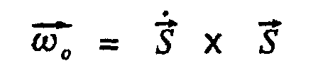 I die Trägheitsmatrix des Raumfahrzeuges istum den Wert von
ωS zu bilden. - Vorrichtung nach einem der vorhergehenden Ansprüche, welche Richtmittel aufweist, um die vorbestimmte (x)-Achse des Raumfahrzeuges auf eine Versetzung relativ zur Richtung der Sonne auszurichten.
- Vorrichtung nach Anspruch 5, welche Mittel aufweist, um die Bewegung der vorbestimmten (x)-Achse des Raumfahrzeuges relativ zur Richtung der Sonne zu beobachten, wobei Schub-Steuermittel (9, 10) für die Schubvorrichtungen vorgesehen sind, um die Schubvorrichtungen am Raumfahrzeug so zu steuern, dass die vorbestimmte (x)-Achse veranlasst wird, um die Versetzungsrichtung zu schwingen.
- Vorrichtung nach Anspruch 6, bei welcher die Schub-Steuermittel (9, 10) zur Steuerung der Schubvorrichtungen so ausgebildet sind, dass die Zündperiode und die Perioden zwischen dem Zünden der Schubvorrichtungen derart gesteuert werden, dass die Bewegung beobachtet werden kann.
- Verfahren zur Steuerung der Drehbewegung eines Raumfahrzeuges um eine vorbestimmte Achse (x) mit den folgenden Schritten:es werden die Charakteristiken der Relativbewegung zwischen der vorbestimmten Achse (x) des Raumfahrzeuges und der Richtung der Sonne festgestellt und geprüft;es wird aus diesen Charakteristiken eine Anzeige der Drehbewegung des Raumfahrzeuges um die vorbestimmte (x)-Achse abgeleitet; undes wird die Anzeige benutzt, um die Drehbewegung des Raumfahrzeuges um diese vorbestimmte Achse zu steuern.
Applications Claiming Priority (2)
| Application Number | Priority Date | Filing Date | Title |
|---|---|---|---|
| FR9606162 | 1996-05-17 | ||
| FR9606162A FR2748721A1 (fr) | 1996-05-17 | 1996-05-17 | Appareil de reglage de la rotation d'un vaisseau spatial autour d'un axe |
Publications (2)
| Publication Number | Publication Date |
|---|---|
| EP0807578A1 EP0807578A1 (de) | 1997-11-19 |
| EP0807578B1 true EP0807578B1 (de) | 2003-08-27 |
Family
ID=9492232
Family Applications (1)
| Application Number | Title | Priority Date | Filing Date |
|---|---|---|---|
| EP97303125A Expired - Lifetime EP0807578B1 (de) | 1996-05-17 | 1997-05-08 | Steuerung der Drehbewegung eines Raumfahrzeuges |
Country Status (4)
| Country | Link |
|---|---|
| US (1) | US6017001A (de) |
| EP (1) | EP0807578B1 (de) |
| DE (1) | DE69724323T2 (de) |
| FR (1) | FR2748721A1 (de) |
Cited By (1)
| Publication number | Priority date | Publication date | Assignee | Title |
|---|---|---|---|---|
| RU2481246C1 (ru) * | 2011-12-14 | 2013-05-10 | Федеральное государственное автономное образовательное учреждение высшего профессионального образования "Северный (Арктический) федеральный университет имени М.В. Ломоносова" (САФУ) | Космический аппарат со стабилизацией вращением |
Families Citing this family (10)
| Publication number | Priority date | Publication date | Assignee | Title |
|---|---|---|---|---|
| US7166825B1 (en) * | 2005-05-17 | 2007-01-23 | Itt Manufacturing Enterprises, Inc. | Solar calibration device and method |
| RU2309876C1 (ru) * | 2006-05-23 | 2007-11-10 | Федеральное государственное научное учреждение "Государственный научно-исследовательский институт прикладной механики и электродинамики" (ФГНУ "НИИ ПМЭ") | Способ управления движением космического аппарата и система управления |
| US7823836B2 (en) * | 2006-12-04 | 2010-11-02 | The Boeing Company | Optimal sun safe attitude for satellite ground tracking |
| US20090166476A1 (en) * | 2007-12-10 | 2009-07-02 | Spacehab, Inc. | Thruster system |
| FR2932163B1 (fr) * | 2008-06-09 | 2010-06-11 | Astrium Sas | Procede de commande d'attitude de satellite et satellite commande en attitude |
| RU2443601C2 (ru) * | 2010-10-26 | 2012-02-27 | Александр Михайлович Гультяев | Ракета |
| FR2980176A1 (fr) * | 2011-09-19 | 2013-03-22 | Astrium Sas | Procede de controle d'attitude d'un satellite et satellite commande en attitude |
| JP6586658B2 (ja) * | 2015-05-12 | 2019-10-09 | 国立研究開発法人宇宙航空研究開発機構 | トルク発生システム、宇宙機の姿勢制御システム、宇宙機の相対位置・速度制御システム |
| US10005568B2 (en) | 2015-11-13 | 2018-06-26 | The Boeing Company | Energy efficient satellite maneuvering |
| US10175700B2 (en) * | 2017-03-22 | 2019-01-08 | The Boeing Company | Methods and apparatus to minimize command dynamics of a satellite |
Citations (2)
| Publication number | Priority date | Publication date | Assignee | Title |
|---|---|---|---|---|
| EP0790542A2 (de) * | 1995-08-11 | 1997-08-20 | Daimler-Benz Aerospace Aktiengesellschaft | Verfahren zur Lageregelung eines dreiachsenstabilisierten, erdorientierten trägheitsmomentstabilisierten Raumfahrzeuges |
| EP0794122A1 (de) * | 1996-03-08 | 1997-09-10 | Space Systems / Loral, Inc. | Von der Erde ausgehende Regelung der Umlaufbahn und der Lage eines Raumfahrzeuges unter der Verwendung einer vorausschauenden Schubdüsen-Auswahllogik und von magnetischen Drehmomenterzeugern |
Family Cites Families (7)
| Publication number | Priority date | Publication date | Assignee | Title |
|---|---|---|---|---|
| JPS6171300A (ja) * | 1984-09-13 | 1986-04-12 | 三菱電機株式会社 | 人工衛星の姿勢角計算装置 |
| US4728061A (en) * | 1985-03-20 | 1988-03-01 | Space Industries, Inc. | Spacecraft operable in two alternative flight modes |
| FR2583873B1 (fr) * | 1985-06-20 | 1987-09-11 | Matra | Procede et dispositif d'injection de satellite sur orbite geostationnaire avec stabilisation suivant les trois axes |
| US5020744A (en) * | 1990-01-12 | 1991-06-04 | General Electric Company | Method for acquiring three-axis earth pointing attitude for an initially spinning spacecraft |
| US5080307A (en) * | 1990-05-14 | 1992-01-14 | Hughes Aircraft Company | Spacecraft earth-pointing attitude acquisition method |
| FR2699701B1 (fr) * | 1992-12-17 | 1995-03-24 | Aerospatiale | Procédé de contrôle d'attitude d'un satellite pointé vers un objet céleste et satellite adapté à sa mise en Óoeuvre. |
| FR2742243B1 (fr) * | 1995-12-06 | 1998-02-13 | Matra Marconi Space France | Procede de commande d'attitude d'un satellite en orbite basse, a acquisition solaire |
-
1996
- 1996-05-17 FR FR9606162A patent/FR2748721A1/fr active Pending
-
1997
- 1997-05-08 EP EP97303125A patent/EP0807578B1/de not_active Expired - Lifetime
- 1997-05-08 DE DE69724323T patent/DE69724323T2/de not_active Expired - Fee Related
- 1997-05-12 US US08/854,812 patent/US6017001A/en not_active Expired - Fee Related
Patent Citations (2)
| Publication number | Priority date | Publication date | Assignee | Title |
|---|---|---|---|---|
| EP0790542A2 (de) * | 1995-08-11 | 1997-08-20 | Daimler-Benz Aerospace Aktiengesellschaft | Verfahren zur Lageregelung eines dreiachsenstabilisierten, erdorientierten trägheitsmomentstabilisierten Raumfahrzeuges |
| EP0794122A1 (de) * | 1996-03-08 | 1997-09-10 | Space Systems / Loral, Inc. | Von der Erde ausgehende Regelung der Umlaufbahn und der Lage eines Raumfahrzeuges unter der Verwendung einer vorausschauenden Schubdüsen-Auswahllogik und von magnetischen Drehmomenterzeugern |
Cited By (1)
| Publication number | Priority date | Publication date | Assignee | Title |
|---|---|---|---|---|
| RU2481246C1 (ru) * | 2011-12-14 | 2013-05-10 | Федеральное государственное автономное образовательное учреждение высшего профессионального образования "Северный (Арктический) федеральный университет имени М.В. Ломоносова" (САФУ) | Космический аппарат со стабилизацией вращением |
Also Published As
| Publication number | Publication date |
|---|---|
| US6017001A (en) | 2000-01-25 |
| DE69724323D1 (de) | 2003-10-02 |
| DE69724323T2 (de) | 2004-02-19 |
| EP0807578A1 (de) | 1997-11-19 |
| FR2748721A1 (fr) | 1997-11-21 |
Similar Documents
| Publication | Publication Date | Title |
|---|---|---|
| EP0460935B1 (de) | System zur Lagestabilisierung eines Raumfahrzeuges mit Momentumrückholung | |
| Crassidis et al. | Attitude estimation using modified Rodrigues parameters | |
| EP0453096B1 (de) | Vorrichtung zur Steuerung der Lage eines Satelliten in einer geneigten Umlaufbahn | |
| US7546983B2 (en) | Spacecraft power acquisition method for wing-stowed configuration | |
| CA2117192C (en) | Three-axis stabilized, earth oriented satellite and corresponding sun and earth acquisition device | |
| US7874519B2 (en) | Spacecraft three-axis attitude acquisition from sun direction measurement | |
| EP0544242B1 (de) | Methode und Vorrichtung zur Kompensation von magnetischen Störmomenten an einem Satelliten | |
| US8321076B2 (en) | On-line inertia estimation for use in controlling an aerospace vehicle | |
| US6142422A (en) | Method to reorient a spacecraft using only initial single axis attitude knowledge | |
| US20050133671A1 (en) | Star-tracker-based attitude determination for spinning spacecraft | |
| US6089508A (en) | Autonomous spacecraft safing with reaction wheels | |
| EP0807578B1 (de) | Steuerung der Drehbewegung eines Raumfahrzeuges | |
| US6263264B1 (en) | Pseudo gyro with unmodeled disturbance torque estimation | |
| US6615117B2 (en) | Attitude determination system and method with outer-loop gyro scale-factor non-linearity calibration | |
| US6020956A (en) | Pseudo gyro | |
| JPH0774739B2 (ja) | 宇宙飛行体、3次元基準座標系再アライン方法、及び航法システム較正方法 | |
| US6282467B1 (en) | Three-axis inertial attitude determination for spinning spacecraft | |
| JPH0420124B2 (de) | ||
| EP0544238B1 (de) | Methode und Vorrichtung zur Kompensation von Sonnenwinden-Gradienten eines Satelliten während einer Sonnenfinsternis | |
| Natanson et al. | Magnetometer-only attitude and rate determination for a gyro-less spacecraft | |
| US6347262B1 (en) | Minimum fuel attitude and nutation controller for spinning spacecraft | |
| Psiaki et al. | ALEXIS spacecraft attitude reconstruction with thermal/flexible motions due to launch damage | |
| US20050090948A1 (en) | Process for determining the position of a spacecraft with the aid of a directional vector and a total angular momentum measurement | |
| Bishop et al. | Proposed CMG momentum management scheme for space station | |
| US7090170B1 (en) | In-orbit satellite sensor alignment determination |
Legal Events
| Date | Code | Title | Description |
|---|---|---|---|
| PUAI | Public reference made under article 153(3) epc to a published international application that has entered the european phase |
Free format text: ORIGINAL CODE: 0009012 |
|
| AK | Designated contracting states |
Kind code of ref document: A1 Designated state(s): DE FR GB IT |
|
| 17P | Request for examination filed |
Effective date: 19980514 |
|
| 17Q | First examination report despatched |
Effective date: 20020610 |
|
| GRAH | Despatch of communication of intention to grant a patent |
Free format text: ORIGINAL CODE: EPIDOS IGRA |
|
| RAP1 | Party data changed (applicant data changed or rights of an application transferred) |
Owner name: ASTRIUM SAS |
|
| GRAS | Grant fee paid |
Free format text: ORIGINAL CODE: EPIDOSNIGR3 |
|
| GRAA | (expected) grant |
Free format text: ORIGINAL CODE: 0009210 |
|
| AK | Designated contracting states |
Designated state(s): DE FR GB IT |
|
| REG | Reference to a national code |
Ref country code: GB Ref legal event code: FG4D |
|
| REF | Corresponds to: |
Ref document number: 69724323 Country of ref document: DE Date of ref document: 20031002 Kind code of ref document: P |
|
| PGFP | Annual fee paid to national office [announced via postgrant information from national office to epo] |
Ref country code: FR Payment date: 20040408 Year of fee payment: 8 |
|
| PGFP | Annual fee paid to national office [announced via postgrant information from national office to epo] |
Ref country code: GB Payment date: 20040415 Year of fee payment: 8 |
|
| PGFP | Annual fee paid to national office [announced via postgrant information from national office to epo] |
Ref country code: DE Payment date: 20040422 Year of fee payment: 8 |
|
| ET | Fr: translation filed | ||
| PLBE | No opposition filed within time limit |
Free format text: ORIGINAL CODE: 0009261 |
|
| STAA | Information on the status of an ep patent application or granted ep patent |
Free format text: STATUS: NO OPPOSITION FILED WITHIN TIME LIMIT |
|
| 26N | No opposition filed |
Effective date: 20040528 |
|
| PG25 | Lapsed in a contracting state [announced via postgrant information from national office to epo] |
Ref country code: IT Free format text: LAPSE BECAUSE OF NON-PAYMENT OF DUE FEES Effective date: 20050508 Ref country code: GB Free format text: LAPSE BECAUSE OF NON-PAYMENT OF DUE FEES Effective date: 20050508 |
|
| PG25 | Lapsed in a contracting state [announced via postgrant information from national office to epo] |
Ref country code: DE Free format text: LAPSE BECAUSE OF NON-PAYMENT OF DUE FEES Effective date: 20051201 |
|
| GBPC | Gb: european patent ceased through non-payment of renewal fee |
Effective date: 20050508 |
|
| PG25 | Lapsed in a contracting state [announced via postgrant information from national office to epo] |
Ref country code: FR Free format text: LAPSE BECAUSE OF NON-PAYMENT OF DUE FEES Effective date: 20060131 |
|
| REG | Reference to a national code |
Ref country code: FR Ref legal event code: ST Effective date: 20060131 |