EP0807721A2 - Drainage fitting for shower trays, bath tubs, cellars, balconies, terraces or the like - Google Patents
Drainage fitting for shower trays, bath tubs, cellars, balconies, terraces or the like Download PDFInfo
- Publication number
- EP0807721A2 EP0807721A2 EP97106760A EP97106760A EP0807721A2 EP 0807721 A2 EP0807721 A2 EP 0807721A2 EP 97106760 A EP97106760 A EP 97106760A EP 97106760 A EP97106760 A EP 97106760A EP 0807721 A2 EP0807721 A2 EP 0807721A2
- Authority
- EP
- European Patent Office
- Prior art keywords
- housing
- odor
- drain fitting
- drain
- odor trap
- Prior art date
- Legal status (The legal status is an assumption and is not a legal conclusion. Google has not performed a legal analysis and makes no representation as to the accuracy of the status listed.)
- Granted
Links
Images
Classifications
-
- E—FIXED CONSTRUCTIONS
- E03—WATER SUPPLY; SEWERAGE
- E03C—DOMESTIC PLUMBING INSTALLATIONS FOR FRESH WATER OR WASTE WATER; SINKS
- E03C1/00—Domestic plumbing installations for fresh water or waste water; Sinks
- E03C1/12—Plumbing installations for waste water; Basins or fountains connected thereto; Sinks
- E03C1/22—Outlet devices mounted in basins, baths, or sinks
-
- E—FIXED CONSTRUCTIONS
- E03—WATER SUPPLY; SEWERAGE
- E03C—DOMESTIC PLUMBING INSTALLATIONS FOR FRESH WATER OR WASTE WATER; SINKS
- E03C1/00—Domestic plumbing installations for fresh water or waste water; Sinks
- E03C1/12—Plumbing installations for waste water; Basins or fountains connected thereto; Sinks
- E03C1/28—Odour seals
-
- E—FIXED CONSTRUCTIONS
- E03—WATER SUPPLY; SEWERAGE
- E03F—SEWERS; CESSPOOLS
- E03F5/00—Sewerage structures
- E03F5/04—Gullies inlets, road sinks, floor drains with or without odour seals or sediment traps
- E03F5/0407—Floor drains for indoor use
- E03F5/0408—Floor drains for indoor use specially adapted for showers
-
- E—FIXED CONSTRUCTIONS
- E03—WATER SUPPLY; SEWERAGE
- E03F—SEWERS; CESSPOOLS
- E03F5/00—Sewerage structures
- E03F5/04—Gullies inlets, road sinks, floor drains with or without odour seals or sediment traps
- E03F5/041—Accessories therefor
-
- E—FIXED CONSTRUCTIONS
- E03—WATER SUPPLY; SEWERAGE
- E03F—SEWERS; CESSPOOLS
- E03F5/00—Sewerage structures
- E03F5/04—Gullies inlets, road sinks, floor drains with or without odour seals or sediment traps
- E03F2005/0416—Gullies inlets, road sinks, floor drains with or without odour seals or sediment traps with an odour seal
- E03F2005/0418—Gullies inlets, road sinks, floor drains with or without odour seals or sediment traps with an odour seal in the form of a bell siphon
Definitions
- the invention relates to a drain fitting for shower and bath tubs, for basements, balconies, patios or the like. with a housing, a connecting surface of the housing carrying a sealing ring, an immersion tube inserted into the housing and delimiting an inflow opening and forming part of the odor trap, which protrudes into a housing space with an overflow displaced upwards relative to the free end of the immersion tube and with one of the Drain chamber of the housing outgoing outlet nozzle.
- a drain fitting of this type is known (EP 0 365 789), in which only the immersion tube can be removed from the housing for cleaning the housing interior from the upper housing opening.
- the drainage space of the housing provided with the drainage connection which is delimited by the outer wall of the housing and by the space belonging to the odor trap, is not accessible for the purpose of cleaning.
- the invention has for its object to design a drain fitting of the type mentioned so that after removal of the immersion tube from the housing, the other housing interiors are easily accessible for cleaning purposes.
- the housing space provided with the upper overflow is formed by an odor trap cup arranged in the casing and locked in the operating position by the dip tube inserted, and the odor trap cup is displaceable in the interior of the housing after removal of the dip tube.
- the odor trap cup is rectangular in plan and has a central indentation on the side facing the drainage pipe.
- housing 1 which consists of a lower part 2 and an upper part 3, which are preferably made of plastic and welded together.
- the upper part 3 forms an upper floor for the housing, which thus delimits an outlet space 4 at the top, from which an outlet nozzle 5 extends.
- the upper floor also forms a connection surface 8 with respect to the outlet opening 7 provided in a floor 6 of a shower tray or a bathtub, which carries a sealing ring 9 which engages around the outlet opening 7 on the underside of the bottom 6.
- the drain fitting is fixed at the edge of the drain opening 7 via a flange ring 10 which is fixed by fastening screws 11, the threaded shaft of which is screwed into a threaded insert 12 which is anchored in a hollow pin 13 closed at the bottom.
- the hollow pins 13 are in one piece with the upper part 3 of the housing 1.
- the fastening screws 11 are supported with their heads 14 on the flange ring 10.
- the screw head has a circumferential groove 15 in which a sealing ring 16 is anchored.
- Hollow pins 17 of a cover 18 are slipped onto the screw heads in a non-positive and positive manner, the hollow pins 17 determining the distance between the cover 18 and the flange ring 10. Through the space between the hollow pins 17, water can flow into the housing 1 through an inflow opening 19, the inflow opening 19 being delimited by the upper end of an immersion tube 10.
- the depth of insertion of the dip tube 20 into the housing 1 is limited by an inwardly projecting shoulder 21 of the upper part 3.
- the free end of the dip tube 20 ends at a distance from a bottom 22 of an odor trap cup 23, which thus forms the odor trap of the drain fitting together with the dip tube.
- the odor trap cup 23 is locked in the operating position of the drain fitting, which is shown in FIGS. 1, 2 and 3, by the immersion tube 20.
- Fig. 2 the outline of the odor trap cup 23 is indicated by hatching.
- the odor trap cup is rectangular and has a central indentation 24 on the side facing the outlet connection 5. 1 shows that there is a gap 26 between the vertical line 25 of the retraction and the immersion tube 20, through which the water flows to the upper overflow 27 and from there into the outlet space 4.
- Partial surfaces of the outer contour of the immersion tube 20 are adapted to engage the odor trap cup 23, partial surfaces of the inner contour of the odor trap cup 23.
- the inner surfaces 28 and 29 of the housing interior form guide surfaces for the longitudinal side walls 30 and 31 of the odor trap cup.
- the odor trap cup 23 can be moved into the position shown in FIGS. 4 and 5. In this position, in which the odor trap cup 23 bears against the inner wall 32 of the housing, the greatest possible access from the upper housing opening is available for cleaning the housing interior between the drain connection 5 and the odor trap cup 23. This access area 33 is shown hatched in FIG. 5.
- the odor trap cup 23 Before the immersion tube 20 can be reinserted after cleaning the interior of the housing, the odor trap cup 23 must be pushed into the front end position in which the outer contour of the front end of the odor trap cup provided with a recess rests on the inner contour 34 shown in dashed lines in FIG. 5.
- the front end position of the odor trap is the subject of FIGS. 1 to 3, while the rear end position for cleaning the interior of the housing is shown in FIGS. 4 and 5.
Landscapes
- Engineering & Computer Science (AREA)
- Water Supply & Treatment (AREA)
- Health & Medical Sciences (AREA)
- Life Sciences & Earth Sciences (AREA)
- Hydrology & Water Resources (AREA)
- Public Health (AREA)
- Environmental & Geological Engineering (AREA)
- Devices For Medical Bathing And Washing (AREA)
- Bathtubs, Showers, And Their Attachments (AREA)
- Sink And Installation For Waste Water (AREA)
- Bay Windows, Entrances, And Structural Adjustments Related Thereto (AREA)
- Residential Or Office Buildings (AREA)
- Specific Sealing Or Ventilating Devices For Doors And Windows (AREA)
- Cosmetics (AREA)
Abstract
Die Ablaufarmatur soll so gestaltet sein, daß zu Reinigungszwecken der Innenraum des Gehäuses (1) nach dem Entfernen des Tauchrohres (20) durch die obere Gehäuseöffnung gut zugänglich ist.The drain fitting should be designed so that the interior of the housing (1) is easily accessible through the upper housing opening after the immersion tube (20) has been removed for cleaning purposes.
Im Gehäuse (1) ist eine Geruchverschlußtasse (23) angeordnet, die in der Betriebsstellung durch das Tauchrohr (20) arretiert ist und nach der Entnahme des Tauchrohres im Gehäuseinnenraum verschiebbar ist.An odor trap cup (23) is arranged in the housing (1), which is locked in the operating position by the immersion tube (20) and can be moved in the interior of the housing after the immersion tube has been removed.
Die Ablaufarmatur ist in Dusch- und Badewannen aber auch in Abläufen verwendbar, die im Keller, auf dem Balkon oder auf Terrassen vorgesehen werden.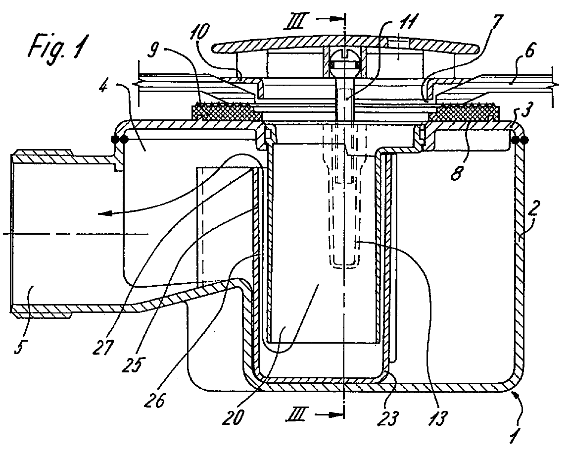
Description
Die Erfindung bezieht sich auf eine Ablaufarmatur für Dusch- und Badewannen, für Keller, Balkone, Terrassen o.dgl. mit einem Gehäuse, einer einen Dichtring tragenden Anschlußfläche des Gehäuses, einem in das Gehäuse eingesetzten, eine Zuflußöffnung begrenzenden, einen Teil des Geruchverschlusses bildenden Tauchrohr, das in einen Gehäuseraum mit einem gegenüber dem freien Ende des Tauchrohres nach oben versetzten Überlauf ragt und mit einem vom Ablaufraum des Gehäuses ausgehenden Ablaufstutzen.The invention relates to a drain fitting for shower and bath tubs, for basements, balconies, patios or the like. with a housing, a connecting surface of the housing carrying a sealing ring, an immersion tube inserted into the housing and delimiting an inflow opening and forming part of the odor trap, which protrudes into a housing space with an overflow displaced upwards relative to the free end of the immersion tube and with one of the Drain chamber of the housing outgoing outlet nozzle.
Es ist eine Ablaufarmatur dieser Art bekannt (EP 0 365 789), bei der zur Reinigung des Gehäuseinnenraums von der oberen Gehäuseöffnung aus ausschließlich das Tauchrohr aus dem Gehäuse entfernt werden kann. Der mit dem Ablaufstutzen versehene Ablaufraum des Gehäuses, der durch die Gehäuseaußenwand und durch den zum Geruchverschluß gehörenden Zwischenraum begrenzt wird, ist zum Zwecke der Reinigung nicht zugänglich.A drain fitting of this type is known (EP 0 365 789), in which only the immersion tube can be removed from the housing for cleaning the housing interior from the upper housing opening. The drainage space of the housing provided with the drainage connection, which is delimited by the outer wall of the housing and by the space belonging to the odor trap, is not accessible for the purpose of cleaning.
Der Erfindung liegt die Aufgabe zugrunde, eine Ablaufarmatur der eingangs genannten Art so zu gestalten, daß nach der Entnahme des Tauchrohres aus dem Gehäuse die weiteren Gehäuseinnenräume zum Zwecke der Reinigung gut zugänglich sind.The invention has for its object to design a drain fitting of the type mentioned so that after removal of the immersion tube from the housing, the other housing interiors are easily accessible for cleaning purposes.
Diese Aufgabe wird erfindungsgemäß dadurch gelöst, daß der mit dem oberen Überlauf versehene Gehäuseraum durch eine im Gehäuse angeordnete, durch das eingesetzte Tauchrohr in der Betriebsstellung arretierte Geruchverschlußtasse gebildet ist und die Geruchverschlußtasse nach der Entnahme des Tauchrohres im Gehäuseinnenraum verschiebbar ist.This object is achieved in that the housing space provided with the upper overflow is formed by an odor trap cup arranged in the casing and locked in the operating position by the dip tube inserted, and the odor trap cup is displaceable in the interior of the housing after removal of the dip tube.
Hierdurch ist nicht nur der Innenraum der Geruchverschlußtasse gut zugänglich, sondern auch der Ablaufraum zwischen der Geruchverschlußtasse und dem Ablaufstutzen und zwar dadurch, daß die Geruchverschlußtasse zu der dem Ablaufstutzen entgegengesetzten Seite des Gehäuses verschoben wird.As a result, not only the interior of the odor trap cup is easily accessible, but also the drainage space between the odor trap cup and the drain connector, namely by moving the odor trap cup to the side of the housing opposite the drain connector.
Bei einer vorteilhaften Ausführungsform ist die Geruchverschlußtasse im Grundriß rechteckförmig ausgebildet und weist an der dem Ablaufstutzen zugewandten Seite eine mittige Einziehung auf. Hierdurch wird die Zugänglichkeit zum Ablaufraum in der unmittelbaren Nachbarschaft des Ablaufstutzens wesentlich verbessert.In an advantageous embodiment, the odor trap cup is rectangular in plan and has a central indentation on the side facing the drainage pipe. As a result, the accessibility to the drainage space in the immediate vicinity of the drainage connection is significantly improved.
Weitere Merkmale der Erfindung ergeben sich aus den Unteransprüchen.Further features of the invention emerge from the subclaims.
Ein Ausführungsbeispiel der erfindungsgemäßen Ablaufarmatur ist in den Zeichnungen dargestellt und wird im folgenden beschrieben. Es zeigen:
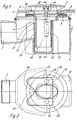
Figur 1- eine an den Boden einer Dusch- oder Badewanne montierte Ablaufarmatur im Längsschnitt,
Figur 2- den der Fig. 1 entsprechenden Grundriß,
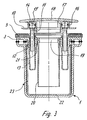
Figur 3- einen Schnitt nach der Linie III-III in Fig. 1,
- Figur 4
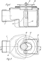
- das Gehäuse nach der Entfernung des Tauchrohres mit aus der Betriebsstellung verschobener Geruchverschlußtasse im Längsschnitt nach IV-IV in Fig. 5 und
Figur 5- den der Fig. 4 entsprechenden Grundriß.
- Figure 1
- a drain fitting mounted on the floor of a shower or bathtub in longitudinal section,
- Figure 2
- 1 corresponding plan,
- Figure 3
- 2 shows a section along the line III-III in FIG. 1,
- Figure 4
- the housing after removal of the dip tube with the odor trap cup moved from the operating position in longitudinal section according to IV-IV in Fig. 5 and
- Figure 5
- the floor plan corresponding to FIG. 4.
Die Ablaufarmatur nach der Fig. 1 weist ein Gehäuse 1 auf, das aus einem Unterteil 2 und einem Oberteil 3 besteht, die vorzugsweise aus Kunststoff gefertigt und miteinander verschweißt sind.1 has a
Das Oberteil 3 bildet einen Oberboden für das Gehäuse, der somit nach oben hin einen Ablaufraum 4 begrenzt, von dem ein Ablaufstutzen 5 ausgeht.The
Der Oberboden bildet ferner in Hinsicht auf die in einem Boden 6 einer Duschwanne oder einer Badewanne angebrachte Ablauföffnung 7 eine Anschlußfläche 8, die einen Dichtring 9 trägt, der die Ablauföffnung 7 an der Unterseite des Bodens 6 umgreift.The upper floor also forms a
Die Festlegung der Ablaufarmatur am Rand der Ablauföffnung 7 erfolgt über einen Flanschring 10, der durch Befestigungsschrauben 11 festgelegt wird, deren Gewindeschaft in einen Gewindeeinsatz 12 eingeschraubt wird, der in einem unten verschlossenen Hohlzapfen 13 verankert ist. In dem Ausführungsbeispiel sind die Hohlzapfen 13 mit dem Oberteil 3 des Gehäuses 1 einstückig. Die Befestigungsschrauben 11 stützen sich mit ihrem Kopf 14 an dem Flanschring 10 ab. Der Schraubenkopf weist eine umlaufende Nut 15 auf, in der ein Dichtungsring 16 verankert ist. Kraft- und formschlüssig werden auf die Schraubenköpfe Hohlzapfen 17 einer Abdeckhaube 18 gestülpt, wobei die Hohlzapfen 17 den Abstand zwischen der Abdeckhaube 18 und dem Flanschring 10 bestimmen. Durch den Raum zwischen den Hohlzapfen 17 kann Wasser durch eine Zuflußöffnung 19 in das Gehäuse 1 einfließen, wobei die Zuflußöffnung 19 vom oberen Ende eines Tauchrohres 10 begrenzt wird.The drain fitting is fixed at the edge of the drain opening 7 via a
Die Einführungstiefe des Tauchrohres 20 in das Gehäuse 1 wird durch eine nach innen vorspringende Schulter 21 des Oberteils 3 begrenzt. Das freie Ende des Tauchrohres 20 endet im Abstand von einem Boden 22 einer Geruchverschlußtasse 23, die somit mit dem Tauchrohr zusammen den Geruchverschluß der Ablaufarmatur bildet.The depth of insertion of the
Die Geruchverschlußtasse 23 wird in der Betriebsstellung der Ablaufarmatur, die in den Fig. 1,2 und 3 aufgezeigt ist, durch das Tauchrohr 20 arretiert.The
In der Fig. 2 ist die Grundrißkontur der Geruchverschlußtasse 23 durch eine Schraffur gekennzeichnet.In Fig. 2, the outline of the
Hieraus ergibt sich, daß die Geruchverschlußtasse rechteckförmig ausgebildet ist und an der dem Ablaufstutzen 5 zugewandten Seite eine mittige Einziehung 24 aufweist. Die Fig. 1 zeigt, daß zwischen der lotrechten Linie 25 der Einziehung und dem Tauchrohr 20 ein Spalt 26 vorhanden ist, durch den das Wasser zum oberen Überlauf 27 und von dort in den Ablaufraum 4 strömt.It follows from this that the odor trap cup is rectangular and has a
Teilflächen der Außenkontur des Tauchrohres 20 sind beim Eingriff in die Geruchverschlußtasse 23 Teilflächen der Innenkontur der Geruchverschlußtasse 23 angepaßt.Partial surfaces of the outer contour of the
Ferner bilden die Innenflächen 28 und 29 des Gehäuseinnenraums Führungsflächen für die Längsseitenwände 30 und 31 der Geruchverschlußtasse.Furthermore, the
Nach der Entnahme des Tauchrohres 20 aus dem Gehäuse kann die Geruchverschlußtasse 23 in die Stellung verschoben werden, die in den Fig. 4 und 5 aufgezeigt ist. In dieser Stellung, in der die Geruchverschlußtasse 23 an der Innenwand 32 des Gehäuses anliegt, steht für die Reinigung des Gehäuseinnenraumes zwischen dem Ablaufstutzen 5 und der Geruchverschlußtasse 23 der größtmögliche Zugang von der oberen Gehäuseöffnung zur Verfügung. Dieser Zugangsbereich 33 ist in der Fig. 5 schraffiert dargestellt.After the
Bevor nach der Reinigung des Gehäuseinnenraums das Tauchrohr 20 wieder eingesetzt werden kann, muß die Geruchverschlußtasse 23 in die vordere Endstellung geschoben werden, in der die Außenkontur der vorderen mit einer Einziehung versehenen Stirnseite der Geruchverschlußtasse an der in Fig. 5 gestrichelt dargestellten Innnekontur 34 anliegt. Die vordere Endstellung der Geruchverschlußtasse ist Gegenstand der Fig. 1 bis 3, während die hintere Endstellung für die Reinigung des Innenraums des Gehäuses in den Fig. 4 und 5 dargestellt ist.Before the
- 11
- Gehäusecasing
- 22nd
- UnterteilLower part
- 33rd
- OberteilTop
- 44th
- AblaufraumDrain room
- 55
- AblaufstutzenDrain connector
- 66
- Bodenground
- 77
- AblauföffnrungDrain opening
- 88th
- AnschlußflächePad
- 99
- DichtringSealing ring
- 1010th
- FlanschringFlange ring
- 1111
- BefestigungsschraubeFastening screw
- 1212th
- GewindeeinsatzThread insert
- 1313
- HohlzapfenHollow spigot
- 1414
- Kopfhead
- 1515
- NutGroove
- 1616
- DichtungsringSealing ring
- 1717th
- HohlzapfenHollow spigot
- 1818th
- AbdeckhaubeCover
- 1919th
- ZuflußöffnungInflow opening
- 2020th
- TauchrohrDip tube
- 2121
- Schultershoulder
- 2222
- Bodenground
- 2323
- GeruchverschlußtasseOdor trap cup
- 2424th
- EinziehungConfiscation
- 2525th
- lotrechte Linievertical line
- 2626
- Spaltgap
- 2727
- ÜberlaufOverflow
- 2828
- InnenflächeInner surface
- 2929
- InnenflächeInner surface
- 3030th
- LängsseitenwandLong side wall
- 3131
- LängsseitenwandLong side wall
- 3232
- InnenwandInterior wall
- 3333
- ZugangsbereichAccess area
- 3434
- InnenkonturInner contour
Claims (7)
Applications Claiming Priority (2)
| Application Number | Priority Date | Filing Date | Title |
|---|---|---|---|
| DE19619942A DE19619942A1 (en) | 1996-05-17 | 1996-05-17 | Drain fitting for shower and bath tubs, for basements, balconies, patios or the like. |
| DE19619942 | 1996-05-17 |
Publications (3)
| Publication Number | Publication Date |
|---|---|
| EP0807721A2 true EP0807721A2 (en) | 1997-11-19 |
| EP0807721A3 EP0807721A3 (en) | 1998-05-27 |
| EP0807721B1 EP0807721B1 (en) | 2002-12-11 |
Family
ID=7794589
Family Applications (1)
| Application Number | Title | Priority Date | Filing Date |
|---|---|---|---|
| EP97106760A Expired - Lifetime EP0807721B1 (en) | 1996-05-17 | 1997-04-24 | Drainage fitting for shower trays, bath tubs, cellars, balconies, terraces or the like |
Country Status (6)
| Country | Link |
|---|---|
| EP (1) | EP0807721B1 (en) |
| AT (1) | ATE229599T1 (en) |
| DE (2) | DE19619942A1 (en) |
| DK (1) | DK0807721T3 (en) |
| ES (1) | ES2184918T3 (en) |
| PT (1) | PT807721E (en) |
Cited By (6)
| Publication number | Priority date | Publication date | Assignee | Title |
|---|---|---|---|---|
| AT408269B (en) * | 1998-07-02 | 2001-10-25 | Vaillant Gmbh | CONDENSING UNIT |
| EP1039047A3 (en) * | 1999-03-23 | 2002-08-28 | Altura Leiden Holding B.V. | Tub with an outlet device |
| EP2108751A3 (en) * | 2008-04-07 | 2012-08-08 | VIEGA GmbH & Co. KG | Drainage fitting for bath or shower basin with floor inlet |
| EP3272954A1 (en) * | 2016-07-22 | 2018-01-24 | Geberit International AG | Drain assembly |
| EP3406810A1 (en) * | 2013-09-12 | 2018-11-28 | BLANCO GmbH + Co KG | Sink with an outflow opening and an outflow module |
| EP3540328A1 (en) * | 2018-03-14 | 2019-09-18 | FingerHaus GmbH | Drainage device |
Families Citing this family (4)
| Publication number | Priority date | Publication date | Assignee | Title |
|---|---|---|---|---|
| DE202004011356U1 (en) * | 2004-07-20 | 2005-12-08 | Viega Gmbh & Co. Kg | Drain system for shower tray has a covered drain fitted with a selected removable trim cover to match the decor scheme |
| DE202007011908U1 (en) | 2007-08-26 | 2007-10-25 | Hidde, Axel R., Dr. Ing. | Surface lighting and / or heating of plumbing installation equipment |
| DE202008010106U1 (en) * | 2008-07-28 | 2009-12-10 | Viega Gmbh & Co. Kg | Drain fitting with a flexible container containing odor trap |
| DE202012103312U1 (en) | 2012-08-30 | 2013-12-04 | Viega Gmbh & Co. Kg | Drain fitting for a sanitary tub or shower tray and sanitary tub or shower tray prepared for this purpose |
Family Cites Families (4)
| Publication number | Priority date | Publication date | Assignee | Title |
|---|---|---|---|---|
| FR390535A (en) * | 1908-05-25 | 1908-10-07 | Bernat Weitzenhoffer | Odorless closure |
| DE839626C (en) * | 1948-10-02 | 1952-05-23 | Paul Matthiessen | Odor trap |
| US3725964A (en) * | 1970-12-17 | 1973-04-10 | G Whitsett | Plumbing trap |
| DE8813543U1 (en) * | 1988-10-28 | 1988-12-15 | Fa. Franz Viegener Ii, 5952 Attendorn | Drain fitting, preferably for shower trays |
-
1996
- 1996-05-17 DE DE19619942A patent/DE19619942A1/en not_active Withdrawn
-
1997
- 1997-04-24 DE DE59708922T patent/DE59708922D1/en not_active Expired - Lifetime
- 1997-04-24 ES ES97106760T patent/ES2184918T3/en not_active Expired - Lifetime
- 1997-04-24 PT PT97106760T patent/PT807721E/en unknown
- 1997-04-24 EP EP97106760A patent/EP0807721B1/en not_active Expired - Lifetime
- 1997-04-24 DK DK97106760T patent/DK0807721T3/en active
- 1997-04-24 AT AT97106760T patent/ATE229599T1/en active
Cited By (7)
| Publication number | Priority date | Publication date | Assignee | Title |
|---|---|---|---|---|
| AT408269B (en) * | 1998-07-02 | 2001-10-25 | Vaillant Gmbh | CONDENSING UNIT |
| EP1039047A3 (en) * | 1999-03-23 | 2002-08-28 | Altura Leiden Holding B.V. | Tub with an outlet device |
| EP2108751A3 (en) * | 2008-04-07 | 2012-08-08 | VIEGA GmbH & Co. KG | Drainage fitting for bath or shower basin with floor inlet |
| EP2108750A3 (en) * | 2008-04-07 | 2012-08-15 | VIEGA GmbH & Co. KG | Drain fitting for bath or shower basins with floor inlet |
| EP3406810A1 (en) * | 2013-09-12 | 2018-11-28 | BLANCO GmbH + Co KG | Sink with an outflow opening and an outflow module |
| EP3272954A1 (en) * | 2016-07-22 | 2018-01-24 | Geberit International AG | Drain assembly |
| EP3540328A1 (en) * | 2018-03-14 | 2019-09-18 | FingerHaus GmbH | Drainage device |
Also Published As
| Publication number | Publication date |
|---|---|
| EP0807721A3 (en) | 1998-05-27 |
| EP0807721B1 (en) | 2002-12-11 |
| DK0807721T3 (en) | 2003-03-31 |
| ES2184918T3 (en) | 2003-04-16 |
| DE59708922D1 (en) | 2003-01-23 |
| DE19619942A1 (en) | 1997-11-20 |
| ATE229599T1 (en) | 2002-12-15 |
| PT807721E (en) | 2003-04-30 |
Similar Documents
| Publication | Publication Date | Title |
|---|---|---|
| EP2286850B1 (en) | Supply unit for dialysis machines | |
| EP2363543B1 (en) | Drainage fitting with cleaning opening | |
| EP0807721A2 (en) | Drainage fitting for shower trays, bath tubs, cellars, balconies, terraces or the like | |
| DE4226685C5 (en) | Overflow fitting for a bath or shower tray | |
| DE2755174A1 (en) | DRAIN CONTAINER WITH ODOR TRAP | |
| DE202008001013U1 (en) | Drain fitting, especially for shower or bathtubs | |
| EP2258905A1 (en) | Drain, in particular for sanitary devices | |
| EP0812966B1 (en) | Outlet for a shower | |
| DE8902878U1 (en) | Flush lifter | |
| DE102006053751A1 (en) | Drainage fitting for e.g. shower tub, has opening formed in partition, and stopper closing opening and comprising starting device that is accessible from interior space of housing, where partition is between space and discharge nozzle | |
| DE3918321A1 (en) | Gulley with an odour-seal insert | |
| EP1775395B1 (en) | Draining device for sanitary installations | |
| DE102004062634B3 (en) | Overflow fitting for a bath tub whose side is fitted with overflow opening attached to its housing, in turn connected to inlet and outlet openings on discharge body using switching, with discharge plate acting as baffle plate | |
| EP1574629B1 (en) | Discharger armature for a sanitary apparatus, especially for a shower tray | |
| DE29712972U1 (en) | Drain fitting, especially for a shower tray | |
| AT396269B (en) | DEVICE FOR MOUNTING A HAND SHOWER ON THE SIDE OF A BATHTUB | |
| DE9415962U1 (en) | Device for removing fibrous waste materials from water drains with an odor trap | |
| DE2824346C2 (en) | Pressurized water connection fitting in a washing machine or dishwasher | |
| DE20012030U1 (en) | Siphon, especially for condensate drainage from boilers or the like. Heat generation | |
| DE4004982C2 (en) | Whirlpool tub | |
| DE3312654C1 (en) | Floor or ceiling drain | |
| EP0757135A1 (en) | Flushing cistern | |
| DE29815758U1 (en) | Box body for a cistern | |
| DE29517550U1 (en) | Floor drain with removable odor trap | |
| DE102023116244A1 (en) | Sanitary basin, especially sink |
Legal Events
| Date | Code | Title | Description |
|---|---|---|---|
| PUAI | Public reference made under article 153(3) epc to a published international application that has entered the european phase |
Free format text: ORIGINAL CODE: 0009012 |
|
| AK | Designated contracting states |
Kind code of ref document: A2 Designated state(s): AT BE CH DE DK ES FR GB IT LI NL PT |
|
| PUAL | Search report despatched |
Free format text: ORIGINAL CODE: 0009013 |
|
| AK | Designated contracting states |
Kind code of ref document: A3 Designated state(s): AT BE CH DE DK ES FR GB IT LI NL PT |
|
| 17P | Request for examination filed |
Effective date: 19980522 |
|
| 17Q | First examination report despatched |
Effective date: 20001201 |
|
| GRAG | Despatch of communication of intention to grant |
Free format text: ORIGINAL CODE: EPIDOS AGRA |
|
| GRAG | Despatch of communication of intention to grant |
Free format text: ORIGINAL CODE: EPIDOS AGRA |
|
| GRAH | Despatch of communication of intention to grant a patent |
Free format text: ORIGINAL CODE: EPIDOS IGRA |
|
| GRAH | Despatch of communication of intention to grant a patent |
Free format text: ORIGINAL CODE: EPIDOS IGRA |
|
| RAP1 | Party data changed (applicant data changed or rights of an application transferred) |
Owner name: FRANZ VIEGENER II GMBH & CO. KG. |
|
| GRAA | (expected) grant |
Free format text: ORIGINAL CODE: 0009210 |
|
| AK | Designated contracting states |
Kind code of ref document: B1 Designated state(s): AT BE CH DE DK ES FR GB IT LI NL PT |
|
| PG25 | Lapsed in a contracting state [announced via postgrant information from national office to epo] |
Ref country code: GB Free format text: LAPSE BECAUSE OF FAILURE TO SUBMIT A TRANSLATION OF THE DESCRIPTION OR TO PAY THE FEE WITHIN THE PRESCRIBED TIME-LIMIT Effective date: 20021211 |
|
| REF | Corresponds to: |
Ref document number: 229599 Country of ref document: AT Date of ref document: 20021215 Kind code of ref document: T |
|
| REG | Reference to a national code |
Ref country code: GB Ref legal event code: FG4D Free format text: NOT ENGLISH |
|
| REG | Reference to a national code |
Ref country code: CH Ref legal event code: EP |
|
| REG | Reference to a national code |
Ref country code: CH Ref legal event code: NV Representative=s name: KATZAROV S.A. |
|
| REF | Corresponds to: |
Ref document number: 59708922 Country of ref document: DE Date of ref document: 20030123 |
|
| REG | Reference to a national code |
Ref country code: DK Ref legal event code: T3 |
|
| REG | Reference to a national code |
Ref country code: ES Ref legal event code: FG2A Ref document number: 2184918 Country of ref document: ES Kind code of ref document: T3 |
|
| REG | Reference to a national code |
Ref country code: PT Ref legal event code: SC4A Free format text: AVAILABILITY OF NATIONAL TRANSLATION Effective date: 20030307 |
|
| GBT | Gb: translation of ep patent filed (gb section 77(6)(a)/1977) | ||
| ET | Fr: translation filed | ||
| PLBE | No opposition filed within time limit |
Free format text: ORIGINAL CODE: 0009261 |
|
| STAA | Information on the status of an ep patent application or granted ep patent |
Free format text: STATUS: NO OPPOSITION FILED WITHIN TIME LIMIT |
|
| 26N | No opposition filed |
Effective date: 20030912 |
|
| REG | Reference to a national code |
Ref country code: CH Ref legal event code: PFA Owner name: VIEGA GMBH & CO. KG Free format text: FRANZ VIEGENER II GMBH & CO. KG.#ENNESTER WEG 9#57439 ATTENDORN (DE) -TRANSFER TO- VIEGA GMBH & CO. KG#ENNESTER WEG 9#57439 ATTENDORN (DE) |
|
| PGFP | Annual fee paid to national office [announced via postgrant information from national office to epo] |
Ref country code: BE Payment date: 20080506 Year of fee payment: 12 |
|
| PGFP | Annual fee paid to national office [announced via postgrant information from national office to epo] |
Ref country code: PT Payment date: 20090318 Year of fee payment: 13 |
|
| BERE | Be: lapsed |
Owner name: FRANZ *VIEGENER II G.M.B.H. & CO. K.G. Effective date: 20090430 |
|
| PG25 | Lapsed in a contracting state [announced via postgrant information from national office to epo] |
Ref country code: BE Free format text: LAPSE BECAUSE OF NON-PAYMENT OF DUE FEES Effective date: 20090430 |
|
| REG | Reference to a national code |
Ref country code: PT Ref legal event code: MM4A Free format text: LAPSE DUE TO NON-PAYMENT OF FEES Effective date: 20101025 |
|
| PG25 | Lapsed in a contracting state [announced via postgrant information from national office to epo] |
Ref country code: PT Free format text: LAPSE BECAUSE OF NON-PAYMENT OF DUE FEES Effective date: 20101025 |
|
| PGFP | Annual fee paid to national office [announced via postgrant information from national office to epo] |
Ref country code: AT Payment date: 20150423 Year of fee payment: 19 |
|
| REG | Reference to a national code |
Ref country code: FR Ref legal event code: PLFP Year of fee payment: 20 |
|
| PGFP | Annual fee paid to national office [announced via postgrant information from national office to epo] |
Ref country code: NL Payment date: 20160422 Year of fee payment: 20 |
|
| PGFP | Annual fee paid to national office [announced via postgrant information from national office to epo] |
Ref country code: CH Payment date: 20160422 Year of fee payment: 20 Ref country code: GB Payment date: 20160422 Year of fee payment: 20 Ref country code: ES Payment date: 20160422 Year of fee payment: 20 Ref country code: DE Payment date: 20160422 Year of fee payment: 20 |
|
| PGFP | Annual fee paid to national office [announced via postgrant information from national office to epo] |
Ref country code: IT Payment date: 20160427 Year of fee payment: 20 Ref country code: FR Payment date: 20160429 Year of fee payment: 20 Ref country code: DK Payment date: 20160421 Year of fee payment: 20 |
|
| REG | Reference to a national code |
Ref country code: AT Ref legal event code: MM01 Ref document number: 229599 Country of ref document: AT Kind code of ref document: T Effective date: 20160424 |
|
| PG25 | Lapsed in a contracting state [announced via postgrant information from national office to epo] |
Ref country code: AT Free format text: LAPSE BECAUSE OF NON-PAYMENT OF DUE FEES Effective date: 20160424 |
|
| REG | Reference to a national code |
Ref country code: CH Ref legal event code: PUE Owner name: VIEGA TECHNOLOGY GMBH AND CO. KG, DE Free format text: FORMER OWNER: VIEGA GMBH AND CO. KG, DE |
|
| REG | Reference to a national code |
Ref country code: DE Ref legal event code: R071 Ref document number: 59708922 Country of ref document: DE |
|
| REG | Reference to a national code |
Ref country code: NL Ref legal event code: MK Effective date: 20170423 |
|
| REG | Reference to a national code |
Ref country code: DK Ref legal event code: EUP Effective date: 20170424 |
|
| REG | Reference to a national code |
Ref country code: CH Ref legal event code: PL |
|
| REG | Reference to a national code |
Ref country code: GB Ref legal event code: PE20 Expiry date: 20170423 |
|
| REG | Reference to a national code |
Ref country code: NL Ref legal event code: PD Owner name: VIEGA TECHNOLOGY GMBH & CO. KG; DE Free format text: DETAILS ASSIGNMENT: CHANGE OF OWNER(S), ASSIGNMENT; FORMER OWNER NAME: VIEGA GMBH & CO. KG Effective date: 20170412 Ref country code: NL Ref legal event code: HC Owner name: VIEGA GMBH & CO. KG; DE Free format text: DETAILS ASSIGNMENT: CHANGE OF OWNER(S), CHANGE OF OWNER(S) NAME; FORMER OWNER NAME: FRANZ VIEGENER II GMBH & CO. KG. Effective date: 20170412 |
|
| PG25 | Lapsed in a contracting state [announced via postgrant information from national office to epo] |
Ref country code: GB Free format text: LAPSE BECAUSE OF EXPIRATION OF PROTECTION Effective date: 20170423 |
|
| REG | Reference to a national code |
Ref country code: ES Ref legal event code: FD2A Effective date: 20170731 |
|
| REG | Reference to a national code |
Ref country code: GB Ref legal event code: 732E Free format text: REGISTERED BETWEEN 20170706 AND 20170715 |
|
| PG25 | Lapsed in a contracting state [announced via postgrant information from national office to epo] |
Ref country code: ES Free format text: LAPSE BECAUSE OF EXPIRATION OF PROTECTION Effective date: 20170425 |
|
| REG | Reference to a national code |
Ref country code: FR Ref legal event code: TP Owner name: VIEGA TECHNOLOGY GMBH & CO. KG, DE Effective date: 20171013 |