EP0807790A2 - Méthode et système pour préparer de l'eau chaude sanitaire - Google Patents
Méthode et système pour préparer de l'eau chaude sanitaire Download PDFInfo
- Publication number
- EP0807790A2 EP0807790A2 EP97107971A EP97107971A EP0807790A2 EP 0807790 A2 EP0807790 A2 EP 0807790A2 EP 97107971 A EP97107971 A EP 97107971A EP 97107971 A EP97107971 A EP 97107971A EP 0807790 A2 EP0807790 A2 EP 0807790A2
- Authority
- EP
- European Patent Office
- Prior art keywords
- heat exchanger
- temperature
- fluid
- circuit
- temperature sensor
- Prior art date
- Legal status (The legal status is an assumption and is not a legal conclusion. Google has not performed a legal analysis and makes no representation as to the accuracy of the status listed.)
- Granted
Links
Images
Classifications
-
- F—MECHANICAL ENGINEERING; LIGHTING; HEATING; WEAPONS; BLASTING
- F24—HEATING; RANGES; VENTILATING
- F24D—DOMESTIC- OR SPACE-HEATING SYSTEMS, e.g. CENTRAL HEATING SYSTEMS; DOMESTIC HOT-WATER SUPPLY SYSTEMS; ELEMENTS OR COMPONENTS THEREFOR
- F24D19/00—Details
- F24D19/10—Arrangement or mounting of control or safety devices
- F24D19/1006—Arrangement or mounting of control or safety devices for water heating systems
- F24D19/1066—Arrangement or mounting of control or safety devices for water heating systems for the combination of central heating and domestic hot water
- F24D19/1069—Arrangement or mounting of control or safety devices for water heating systems for the combination of central heating and domestic hot water regulation in function of the temperature of the domestic hot water
Definitions
- the invention relates to an arrangement and a method for providing hot domestic water with a primary circuit with a fluid, a device providing hot or hot fluid and a conveying device for the fluid, a secondary circuit for the domestic water to be heated, a heat exchanger for heat transfer from the fluid of the primary circuit on the process water in the secondary circuit, a control device for the conveyor and a temperature sensor in the primary or secondary circuit.
- the hot domestic water is conventionally provided by means of a heating source in a domestic water storage tank, a so-called boiler, which also takes on the task of temporarily storing energy.
- This fluid is usually also water, but for example the water of a heating system, which is not intended for normal consumption or use.
- a process water queue runs through a heating water storage tank, during which process hot water is to be reheated via an assigned heating device.
- a temperature sensor is arranged in the thermally conductive contact with the hot water coil in the area where the hot water coil flows into the heating water tank. After the start of the tap, cool fresh water flows through exactly this junction area, and the resulting small temperature drop is transferred to the temperature sensor, which can thus be used to control the heating device.
- the process water is heated with the help of an external heat exchanger as a water heater.
- the fluid or heating water is pumped in a primary circuit through the heat exchanger, which heats the process water in the secondary circuit.
- Cold water is thus fed to the heat exchanger in the secondary circuit and brought there to the desired useful temperature by transferring the heat from the heating water from the heat generator through the heat exchanger to the process water.
- the hot water is available in a heated form.
- So-called stratified superchargers are particularly suitable as sources or stores for the hot fluid or heating water.
- the hotter amounts of water or fluid are layered on top of one another in a storage vessel.
- the primary circuit removes hot fluid from the top of the storage vessel, it flows through the heat exchanger mentioned and is then cooled again and is then stratified in a region of the storage vessel corresponding to the temperature between the amounts of water or fluid located there.
- a control device In order to be able to provide a reasonably constant water temperature for the process water, a control device can be provided.
- Such a control device is known for example from CH-PS 285 708; a temperature sensor is provided there, which is provided either in the primary circuit or also in the secondary circuit and acts on a three-way valve and thus regulates the primary-side temperature in the heat exchanger by changing the mixing ratio of the heating water in the primary circuit.
- the object of the invention is to propose an arrangement and a method for providing hot industrial water which does not require such flow monitors and at the same time creates an inexpensive control option.
- a first temperature sensor is arranged both in the primary circuit in the heat exchanger or in the line on the outlet side with respect to the heat exchanger and in the secondary circuit in the heat exchanger or in the second line temperature sensor in the outlet side with respect to the heat exchanger, and in that the control device has a circuit which switches on the conveying device when the temperature drops below a desired value and / or a temperature gradient amount exceeding a desired value at the second temperature sensor and switches off the conveying device at the first temperature sensor when the temperature increases above a desired value and / or when the temperature gradient exceeds a desired value.
- the object is achieved in that the temperature is measured both in the primary circuit in the heat exchanger or in the line on the outlet side with respect to the heat exchanger and in the secondary circuit in the heat exchanger or in the line on the outlet side with respect to the heat exchanger, and in that the temperature drops below a setpoint and / or via a setpoint increasing temperature gradient in the heat exchanger or in the line leading away from the heat exchanger in the secondary circuit, the conveying device begins to convey the fluid in the primary circuit, and that when the setpoint temperature rises and / or the setpoint temperature gradient increases in the heat exchanger or in the line away from the heat exchanger in the primary circuit, the delivery of the fluid in the primary circuit is ended.
- the temperature sensor in the process water circuit is particularly preferably arranged directly at the outlet of the heat exchanger in the secondary circuit. If the tap in the hot water pipe is opened after a previous standstill and hot water is requested, the hot water begins to flow in the secondary circuit.
- the temperature which is initially at the level of the heat exchanger, i.e. at a relatively high level, begins to drop quite spontaneously when the water from the cold water supply of the process water runs through the heat exchanger, whose heat reserve naturally decreases.
- This falling temperature is immediately recognized by the temperature sensor. In one variant, this can be done in that this temperature falls below a desired value; in a preferred variant, this is simply determined by the temperature gradient.
- the latter also has the advantage that when the control system is started up with a cold store (initial start-up), the conveyor device is not switched on, even though a setpoint is undershot.
- the conveyor does not switch off yet, as process water continues to be withdrawn and there is therefore still a need for heat supply.
- the temperature gradient on this second temperature sensor in the secondary circuit is now very low or fluctuates around a zero value and the temperature is therefore constant and also above the setpoint, this is not a switch-on criterion: the conveyor is still running.
- the thermal energy of the hot fluid is no longer released to the process water in the primary circuit, since the process water is already at the appropriate temperature and requires no additional supply.
- the fluid in the primary circuit flows through the heat exchanger without having completely lost its heat, which leads to a very rapid temperature rise in the region of the first temperature sensor on the output side of the heat exchanger in the primary circuit.
- This rising temperature can be used as a switch-off criterion either by exceeding a setpoint or also by recognizing a temperature gradient, and thus stops the conveyor.
- a particularly quick response is ensured if the respective temperature sensors are provided on the heat exchanger on the output side. In certain applications, it may even make sense to provide the temperature sensors inside the heat exchanger. The closer the temperature sensors are to the heat exchanger, the faster they can detect any changes in temperature and thus prevent the creation of undesired cold water areas in the hot water supply.
- the conveying device in particular a pump, in the primary circuit should, if possible, be arranged in the line leading away from the heat exchanger, that is to say in its line on the outlet side.
- colder primary fluid flows through the conveying device, particularly when it is at a standstill, which is more favorable for its durability and ease of maintenance.
- the first temperature sensor is arranged between the heat exchanger and the conveyor.
- the arrangement and the method can be used particularly well if the warm or hot fluid is provided by a buffer store, but the flow of a boiler, a district heating network or the like are also suitable.
- a third temperature sensor is also provided, which is located either in the buffer store or in the line from the buffer store to the heat exchanger.
- the control device has a further circuit with which the temperature determined by the third temperature sensor is used when determining the setpoint value of the temperature at the second temperature sensor. In this way, the case can be taken into account that there may not be enough warm or hot fluid in the buffer storage, for example when the system is started up for the first time or simply after considerable consumption has already taken place. It can then be prevented by lowering the setpoint values of the temperatures at the second temperature sensor that the buffer memory continuously releases further contents without it being possible at all to achieve the setpoint values otherwise desired by the control device.
- the invention makes it possible, by observing the storage tank temperature in relation to the desired water temperature, to prevent the storage tank from mixing due to an excessive flow rate of the primary circuit and to maintain standby operation.
- a diagram of the temperature curve at various measuring points on the heat exchanger and storage tank is considered in relation to a typical user behavior, ie different amounts of water taken off and the turning on and off of the tap were simulated. If the heat storage tank does not have the temperature required for the hot water setpoint temperature, the hot water setpoint temperature is reduced from the storage tank temperature adjustable difference is calculated. The hot water target temperature is therefore not an absolute value, but - if the storage tank temperature is too low - also dependent on this.
- the pump would run fully in order to get as close as possible to the set hot water setpoint with the maximum available energy. Due to the maximum primary flow, the primary return temperature rises unnecessarily high. This can lead to rapid disintegration or temperature stratification in the storage tank, which results in a further drop in the storage tank temperature.
- the actual hot water setpoint can therefore be calculated again from the storage tank temperature minus the set difference. This prevents the primary flow from being exceeded above a desired limit value and the storage stratification is retained under all operating conditions.
- a pump runtime element is useful in order to bridge temperature fluctuations after switching on, which could be regarded as a switch-off criterion. Furthermore, it is normally chosen so that enough thermal energy is pumped into the system to bring the heat exchanger and thus the hot water outlet to the required temperature.
- the conveying device is a speed-controlled pump and the regulating device has a circuit which, depending on the temperature gradient at the second temperature sensor, also regulates the conveying speed of the conveying device, that is to say, for example, the speed.
- one or both temperature sensors are arranged within the insulation of the buffer store. This allows the heat exchanger to reach the target temperature are kept, simply by heat conduction automatically from the buffer storage.
- the control device can also use a special combination of different process stages.
- a start-up control program can be run for a limited period of time, for example 30 seconds, which provides for a constantly predetermined pump speed, or a special P-I-D setting that can react very quickly to changes in temperature. In this way, the target temperature can be maintained and cold water holes avoided at the start of hot water tapping.
- the use of the temperature gradient amount as a switch-on criterion has also proven to be useful for the following reason: After opening the hot water tap, the hot water in the heat exchanger is at a slightly higher level than the thermal sensor on the output side of the heat exchanger can detect a short distance away.
- One of the effects of this is that, due to convection currents on the primary side in the heat exchanger, a very slightly higher temperature is set there than can be the case with a non-running secondary circuit in the process water. This effect is usually hardly measurable.
- control device determines the amount of the temperature gradient due to its falling and can react accordingly.
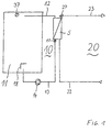
- the purely schematic illustration which shows only the most essential parts of the entire arrangement, shows a primary circuit 10 in the left half and a secondary circuit 20 in the right half.
- the primary circuit 10 begins on the left with a device that provides warm or hot fluid, here a buffer store 11. From this buffer store 11, a line 12 leads to a heat exchanger 5. After passing through the heat exchanger 5 and giving off the thermal energy in it, the fluid leads in the primary circuit 10 back via an outlet-side line 13 to the buffer store 11.
- a conveying device here a pump 14, is provided, between the heat exchanger 5 and the pump 14 a first temperature sensor 17 is arranged.
- the hot fluid is usually removed from the upper region of the buffer store 11, fed to the heat exchanger 5 and returned by the pump 14 to the lower region of the buffer store 11.
- a fluid single-layer device 18 which is only indicated schematically here, can be provided, for example a stratified charger according to EP 0 384 423 B1.
- hot fluid remains undisturbed in the upper region, where the line 12 also draws it off.
- Additional hot fluid or thermal energy for heating existing fluids can be provided by layering fluids heated by solar collectors and / or by installing burners (not shown in each case) or in another way.
- the secondary circuit 20 on the right side begins with a cold water supply line 22, with which cold process water (drinking water, wash water, etc.) is fed to the heat exchanger 5.
- the heat energy of the primary circuit 10 running in countercurrent is received in the heat exchanger 5.
- the process water leaves it again and flows through an outlet-side line 23 to the hot water withdrawal point.
- the promotion in the secondary circuit can take place, for example, in that the cold water supply takes place under pressure and the hot water withdrawal point by a tap may block this pressure.
- the temperature sensor 27 detects the hot water temperature as close as possible to the heat exchanger 5.
- the temperature sensors 17 and 27 report their values to a control device, not shown.
- a third temperature sensor 37 which records the temperature of the hot fluid in the upper region of the buffer store 11.
- the control device then controls the pump 14, on the one hand the switching on and off and on the other hand also the speed or conveying speed, if applicable.
Landscapes
- Engineering & Computer Science (AREA)
- Physics & Mathematics (AREA)
- Thermal Sciences (AREA)
- Chemical & Material Sciences (AREA)
- Combustion & Propulsion (AREA)
- Mechanical Engineering (AREA)
- General Engineering & Computer Science (AREA)
- Steam Or Hot-Water Central Heating Systems (AREA)
- Instantaneous Water Boilers, Portable Hot-Water Supply Apparatuses, And Control Of Portable Hot-Water Supply Apparatuses (AREA)
- Heat-Pump Type And Storage Water Heaters (AREA)
- Control Of Combustion (AREA)
Applications Claiming Priority (2)
| Application Number | Priority Date | Filing Date | Title |
|---|---|---|---|
| DE19619566 | 1996-05-15 | ||
| DE19619566A DE19619566C1 (de) | 1996-05-15 | 1996-05-15 | Anordnung und Verfahren zur Bereitstellung von warmem Brauchwasser |
Publications (3)
| Publication Number | Publication Date |
|---|---|
| EP0807790A2 true EP0807790A2 (fr) | 1997-11-19 |
| EP0807790A3 EP0807790A3 (fr) | 1998-11-18 |
| EP0807790B1 EP0807790B1 (fr) | 2003-08-06 |
Family
ID=7794376
Family Applications (1)
| Application Number | Title | Priority Date | Filing Date |
|---|---|---|---|
| EP97107971A Expired - Lifetime EP0807790B1 (fr) | 1996-05-15 | 1997-05-15 | Méthode et système pour préparer de l'eau chaude sanitaire |
Country Status (3)
| Country | Link |
|---|---|
| EP (1) | EP0807790B1 (fr) |
| AT (1) | ATE246784T1 (fr) |
| DE (1) | DE19619566C1 (fr) |
Cited By (7)
| Publication number | Priority date | Publication date | Assignee | Title |
|---|---|---|---|---|
| EP0989372A3 (fr) * | 1998-09-24 | 2000-04-19 | Gledhill (Water Storage) Limited | Appareil de chauffage |
| GB2368896A (en) * | 2000-11-11 | 2002-05-15 | Gledhill Water Storage | Heat exchange system, temperature sensor arrangement and operation |
| EP1906104A1 (fr) * | 2006-09-18 | 2008-04-02 | Vaillant GmbH | Procédé de reconnaissance de la nécessité du chargement d'un ballon d'eau chaude |
| EP2963350A1 (fr) * | 2014-07-02 | 2016-01-06 | Markus Keitsch | Systeme destine a un fonctionnement a economie d'energie d'un echangeur thermique utilise ou exploite par intermittence dans un systeme de conduites, en particulier destine au chauffage de l'eau potable |
| DE102015113140A1 (de) | 2014-08-15 | 2016-02-18 | Solvis Gmbh & Co. Kg | Heizungseinrichtung mit Warmwasserspeicher und darin angeordnetem Wasserzufuhrrohr |
| EP2503252A3 (fr) * | 2011-03-18 | 2016-08-10 | Markus Keitsch | Système de préparation d'eau chaude non potable dans un système de conduites |
| CN110579023A (zh) * | 2018-06-11 | 2019-12-17 | 芜湖美的厨卫电器制造有限公司 | 壁挂炉水路循环的控制方法、装置及系统 |
Families Citing this family (6)
| Publication number | Priority date | Publication date | Assignee | Title |
|---|---|---|---|---|
| DE29822245U1 (de) * | 1998-12-15 | 1999-07-15 | LIMAX Öl-Gas-Fernwärmetechnik GmbH, 01979 Lauchhammer | Warmwasserbereiter für Heizungswasserpuffersysteme |
| DE10032714A1 (de) | 2000-07-07 | 2002-01-24 | Solvis Solarsysteme Gmbh | Anordnung und Verfahren zur Bereitstellung von warmem Brauchwasser |
| DE102004018034B4 (de) * | 2004-04-14 | 2014-07-24 | Stiebel Eltron Gmbh & Co. Kg | Verfahren zur Einschaltung einer Wärmepumpe in Verbindung mit einem Brauchwasserspeicher für Wärmepumpen |
| DE102007028656B4 (de) * | 2007-06-21 | 2013-08-14 | Robert Bosch Gmbh | Warmwasserbereiter |
| DE102008029654A1 (de) | 2008-06-24 | 2009-12-31 | Solvis Gmbh & Co. Kg | Anordnung und Verfahren zur Bereitstellung von warmem Trinkwasser mit einem Wärmeübertrager |
| DE102016102718B4 (de) | 2016-02-16 | 2019-11-14 | Hoval Aktiengesellschaft | Trinkwassererwärmungssystem |
Citations (4)
| Publication number | Priority date | Publication date | Assignee | Title |
|---|---|---|---|---|
| CH285708A (de) | 1950-04-20 | 1952-09-30 | Gustavsbergs Fabriker Ab | Anlage zum Wärmen von Gebrauchswasser. |
| EP0384423A1 (fr) | 1989-02-23 | 1990-08-29 | SOLVIS Energiesysteme GmbH | Accumulateur d'eau chaude avec échangeur de chaleur pour eau sanitaire avec élément de chauffage extérieur et avec distributeur pour l'eau d'alimentation |
| DE4035115A1 (de) | 1990-03-12 | 1991-09-19 | Sandler Energietechnik | Anordnung zur entnahme von warmen oder heissem brauchwasser von trinkwasserqualitaet aus einer heizanlage |
| DE29519473U1 (de) | 1995-12-08 | 1996-02-22 | Buderus Heiztechnik Gmbh, 35576 Wetzlar | Brauchwassererwärmer |
Family Cites Families (4)
| Publication number | Priority date | Publication date | Assignee | Title |
|---|---|---|---|---|
| NL8503345A (nl) * | 1985-12-04 | 1987-07-01 | Nefit Nv | Inrichting voor het sturen van een warmwatervoorziening. |
| EP0621450A3 (fr) * | 1993-04-23 | 1995-03-22 | Georg Lachenmeier | Procédé et appareil pour chauffer de l'eau sanitaire. |
| GB2293438A (en) * | 1994-09-20 | 1996-03-27 | Gledhill Water Storage | The control of water heating apparatus to prevent scalding |
| DE19512025C2 (de) * | 1995-03-31 | 1999-01-28 | Stiebel Eltron Gmbh & Co Kg | Gasheizgerät |
-
1996
- 1996-05-15 DE DE19619566A patent/DE19619566C1/de not_active Expired - Fee Related
-
1997
- 1997-05-15 AT AT97107971T patent/ATE246784T1/de not_active IP Right Cessation
- 1997-05-15 EP EP97107971A patent/EP0807790B1/fr not_active Expired - Lifetime
Patent Citations (4)
| Publication number | Priority date | Publication date | Assignee | Title |
|---|---|---|---|---|
| CH285708A (de) | 1950-04-20 | 1952-09-30 | Gustavsbergs Fabriker Ab | Anlage zum Wärmen von Gebrauchswasser. |
| EP0384423A1 (fr) | 1989-02-23 | 1990-08-29 | SOLVIS Energiesysteme GmbH | Accumulateur d'eau chaude avec échangeur de chaleur pour eau sanitaire avec élément de chauffage extérieur et avec distributeur pour l'eau d'alimentation |
| DE4035115A1 (de) | 1990-03-12 | 1991-09-19 | Sandler Energietechnik | Anordnung zur entnahme von warmen oder heissem brauchwasser von trinkwasserqualitaet aus einer heizanlage |
| DE29519473U1 (de) | 1995-12-08 | 1996-02-22 | Buderus Heiztechnik Gmbh, 35576 Wetzlar | Brauchwassererwärmer |
Cited By (10)
| Publication number | Priority date | Publication date | Assignee | Title |
|---|---|---|---|---|
| EP0989372A3 (fr) * | 1998-09-24 | 2000-04-19 | Gledhill (Water Storage) Limited | Appareil de chauffage |
| GB2368896A (en) * | 2000-11-11 | 2002-05-15 | Gledhill Water Storage | Heat exchange system, temperature sensor arrangement and operation |
| GB2368896B (en) * | 2000-11-11 | 2003-10-29 | Gledhill Water Storage | Improvements relating to heating apparatus |
| EP1906104A1 (fr) * | 2006-09-18 | 2008-04-02 | Vaillant GmbH | Procédé de reconnaissance de la nécessité du chargement d'un ballon d'eau chaude |
| AT504286B1 (de) * | 2006-09-18 | 2008-09-15 | Vaillant Austria Gmbh | Verfahren zur ladung eines warmwasserspeichers |
| EP2503252A3 (fr) * | 2011-03-18 | 2016-08-10 | Markus Keitsch | Système de préparation d'eau chaude non potable dans un système de conduites |
| EP2963350A1 (fr) * | 2014-07-02 | 2016-01-06 | Markus Keitsch | Systeme destine a un fonctionnement a economie d'energie d'un echangeur thermique utilise ou exploite par intermittence dans un systeme de conduites, en particulier destine au chauffage de l'eau potable |
| DE102015113140A1 (de) | 2014-08-15 | 2016-02-18 | Solvis Gmbh & Co. Kg | Heizungseinrichtung mit Warmwasserspeicher und darin angeordnetem Wasserzufuhrrohr |
| CN110579023A (zh) * | 2018-06-11 | 2019-12-17 | 芜湖美的厨卫电器制造有限公司 | 壁挂炉水路循环的控制方法、装置及系统 |
| CN110579023B (zh) * | 2018-06-11 | 2024-01-16 | 芜湖美的厨卫电器制造有限公司 | 壁挂炉水路循环的控制方法、装置及系统 |
Also Published As
| Publication number | Publication date |
|---|---|
| EP0807790A3 (fr) | 1998-11-18 |
| ATE246784T1 (de) | 2003-08-15 |
| EP0807790B1 (fr) | 2003-08-06 |
| DE19619566C1 (de) | 1997-11-27 |
Similar Documents
| Publication | Publication Date | Title |
|---|---|---|
| EP0807790B1 (fr) | Méthode et système pour préparer de l'eau chaude sanitaire | |
| CH673901A5 (fr) | ||
| EP2416073A2 (fr) | Procédé et dispositif destinés au chauffage d'un fluide dans une mémoire tampon | |
| DE3012308A1 (de) | Steuersystem fuer eine absorptionskaeltemaschine, absorptionskaeltemaschine und verfahren zu deren betrieb | |
| DE19859364C2 (de) | Wärmeversorgungsanlage mit Spitzenlastbegrenzung | |
| DE3714261C1 (de) | Brennwert-Heizkessel und Verfahren zu seinem Betreiben | |
| DE2843929A1 (de) | Anordnung zur steuerung der raumtemperatur | |
| EP1170554B1 (fr) | Ensemble et procédé pour préparer de l'eau chaude sanitaire | |
| EP0892223B1 (fr) | Dispositif de commande et de régulation pour système de chauffage | |
| EP2667104B1 (fr) | Installation et procédé de chauffage d'eau potable | |
| DE19810416B4 (de) | Heiz- bzw. Kühlanlage mit mindestens einer Wärme- bzw. Kältequelle | |
| DE2606535A1 (de) | Temperatursystem | |
| EP0038318A1 (fr) | Dispositif de réglage pour le réglage du chauffage d'eau sanitaire pour un ballon de stockage | |
| DE3620929A1 (de) | Verfahren und einrichtung zur regelung mindestens einer heizung | |
| DE3030565A1 (de) | Heizkessel fuer heizungsanlagen | |
| EP0880659A1 (fr) | Regulateur solaire a effet modulateur | |
| EP3385624A1 (fr) | Procédé de fonctionnement d'une installation de préparation d'eau sanitaire ou de chauffage, dispositif de commande et/ou de réglage pour une installation de préparation d'eau sanitaire et de chauffage et installation de préparation d'eau sanitaire | |
| DE69105742T2 (de) | Zentralheizungsanlage. | |
| EP0192225A2 (fr) | Procédé et dispositif de régulation de température de locaux | |
| DE19824543C1 (de) | Verfahren und Vorrichtung zur Regelung von Umwälzpumpen in den Solarkollektorkreisen von Solaranlagen mit Speicher | |
| DE19745143C1 (de) | Verfahren zur Regelung der Förderleistung einer Heizwasserpumpe | |
| AT507569B1 (de) | Verfahren zur erwärmung von brauchwasser | |
| DE102004042866B4 (de) | Drain-Back-Solaranlage | |
| DE19824034C2 (de) | Brauchwasser-Erwärmungsanlage | |
| AT414272B (de) | Schichtenspeicher |
Legal Events
| Date | Code | Title | Description |
|---|---|---|---|
| PUAI | Public reference made under article 153(3) epc to a published international application that has entered the european phase |
Free format text: ORIGINAL CODE: 0009012 |
|
| AK | Designated contracting states |
Kind code of ref document: A2 Designated state(s): AT CH DK ES FR GB GR IT LI NL PT SE |
|
| PUAL | Search report despatched |
Free format text: ORIGINAL CODE: 0009013 |
|
| AK | Designated contracting states |
Kind code of ref document: A3 Designated state(s): AT CH DK ES FR GB GR IT LI NL PT SE |
|
| 17P | Request for examination filed |
Effective date: 19990517 |
|
| RAP1 | Party data changed (applicant data changed or rights of an application transferred) |
Owner name: SOLVIS SOLARSYSTEME GMBH |
|
| 17Q | First examination report despatched |
Effective date: 20010619 |
|
| GRAH | Despatch of communication of intention to grant a patent |
Free format text: ORIGINAL CODE: EPIDOS IGRA |
|
| GRAH | Despatch of communication of intention to grant a patent |
Free format text: ORIGINAL CODE: EPIDOS IGRA |
|
| RAP1 | Party data changed (applicant data changed or rights of an application transferred) |
Owner name: SOLVIS GMBH & CO. KG |
|
| GRAA | (expected) grant |
Free format text: ORIGINAL CODE: 0009210 |
|
| AK | Designated contracting states |
Designated state(s): AT CH DK ES FR GB GR IT LI NL PT SE |
|
| PG25 | Lapsed in a contracting state [announced via postgrant information from national office to epo] |
Ref country code: NL Free format text: LAPSE BECAUSE OF FAILURE TO SUBMIT A TRANSLATION OF THE DESCRIPTION OR TO PAY THE FEE WITHIN THE PRESCRIBED TIME-LIMIT Effective date: 20030806 Ref country code: GB Free format text: LAPSE BECAUSE OF FAILURE TO SUBMIT A TRANSLATION OF THE DESCRIPTION OR TO PAY THE FEE WITHIN THE PRESCRIBED TIME-LIMIT Effective date: 20030806 Ref country code: FR Free format text: LAPSE BECAUSE OF FAILURE TO SUBMIT A TRANSLATION OF THE DESCRIPTION OR TO PAY THE FEE WITHIN THE PRESCRIBED TIME-LIMIT Effective date: 20030806 |
|
| REG | Reference to a national code |
Ref country code: GB Ref legal event code: FG4D Free format text: NOT ENGLISH |
|
| REG | Reference to a national code |
Ref country code: CH Ref legal event code: EP |
|
| REG | Reference to a national code |
Ref country code: CH Ref legal event code: NV Representative=s name: KATZAROV S.A. |
|
| PG25 | Lapsed in a contracting state [announced via postgrant information from national office to epo] |
Ref country code: SE Free format text: LAPSE BECAUSE OF FAILURE TO SUBMIT A TRANSLATION OF THE DESCRIPTION OR TO PAY THE FEE WITHIN THE PRESCRIBED TIME-LIMIT Effective date: 20031106 Ref country code: GR Free format text: LAPSE BECAUSE OF FAILURE TO SUBMIT A TRANSLATION OF THE DESCRIPTION OR TO PAY THE FEE WITHIN THE PRESCRIBED TIME-LIMIT Effective date: 20031106 Ref country code: DK Free format text: LAPSE BECAUSE OF FAILURE TO SUBMIT A TRANSLATION OF THE DESCRIPTION OR TO PAY THE FEE WITHIN THE PRESCRIBED TIME-LIMIT Effective date: 20031106 |
|
| PG25 | Lapsed in a contracting state [announced via postgrant information from national office to epo] |
Ref country code: ES Free format text: LAPSE BECAUSE OF FAILURE TO SUBMIT A TRANSLATION OF THE DESCRIPTION OR TO PAY THE FEE WITHIN THE PRESCRIBED TIME-LIMIT Effective date: 20031117 |
|
| NLV1 | Nl: lapsed or annulled due to failure to fulfill the requirements of art. 29p and 29m of the patents act | ||
| PG25 | Lapsed in a contracting state [announced via postgrant information from national office to epo] |
Ref country code: PT Free format text: LAPSE BECAUSE OF FAILURE TO SUBMIT A TRANSLATION OF THE DESCRIPTION OR TO PAY THE FEE WITHIN THE PRESCRIBED TIME-LIMIT Effective date: 20040106 |
|
| GBV | Gb: ep patent (uk) treated as always having been void in accordance with gb section 77(7)/1977 [no translation filed] |
Effective date: 20030806 |
|
| PLBE | No opposition filed within time limit |
Free format text: ORIGINAL CODE: 0009261 |
|
| STAA | Information on the status of an ep patent application or granted ep patent |
Free format text: STATUS: NO OPPOSITION FILED WITHIN TIME LIMIT |
|
| 26N | No opposition filed |
Effective date: 20040507 |
|
| EN | Fr: translation not filed | ||
| PGFP | Annual fee paid to national office [announced via postgrant information from national office to epo] |
Ref country code: AT Payment date: 20080531 Year of fee payment: 12 |
|
| PGFP | Annual fee paid to national office [announced via postgrant information from national office to epo] |
Ref country code: IT Payment date: 20080529 Year of fee payment: 12 |
|
| PGFP | Annual fee paid to national office [announced via postgrant information from national office to epo] |
Ref country code: CH Payment date: 20090427 Year of fee payment: 13 |
|
| PG25 | Lapsed in a contracting state [announced via postgrant information from national office to epo] |
Ref country code: AT Free format text: LAPSE BECAUSE OF NON-PAYMENT OF DUE FEES Effective date: 20090515 |
|
| REG | Reference to a national code |
Ref country code: CH Ref legal event code: PL |
|
| PG25 | Lapsed in a contracting state [announced via postgrant information from national office to epo] |
Ref country code: LI Free format text: LAPSE BECAUSE OF NON-PAYMENT OF DUE FEES Effective date: 20100531 Ref country code: CH Free format text: LAPSE BECAUSE OF NON-PAYMENT OF DUE FEES Effective date: 20100531 |
|
| PG25 | Lapsed in a contracting state [announced via postgrant information from national office to epo] |
Ref country code: IT Free format text: LAPSE BECAUSE OF NON-PAYMENT OF DUE FEES Effective date: 20090515 |