EP0808076A1 - Système acoustique à effet spatial - Google Patents
Système acoustique à effet spatial Download PDFInfo
- Publication number
- EP0808076A1 EP0808076A1 EP96107860A EP96107860A EP0808076A1 EP 0808076 A1 EP0808076 A1 EP 0808076A1 EP 96107860 A EP96107860 A EP 96107860A EP 96107860 A EP96107860 A EP 96107860A EP 0808076 A1 EP0808076 A1 EP 0808076A1
- Authority
- EP
- European Patent Office
- Prior art keywords
- signal
- signals
- surround sound
- stereo
- circuit
- Prior art date
- Legal status (The legal status is an assumption and is not a legal conclusion. Google has not performed a legal analysis and makes no representation as to the accuracy of the status listed.)
- Granted
Links
- 230000004048 modification Effects 0.000 claims abstract description 11
- 238000012986 modification Methods 0.000 claims abstract description 11
- 230000000295 complement effect Effects 0.000 claims 1
- 230000001502 supplementing effect Effects 0.000 claims 1
- 230000000694 effects Effects 0.000 abstract description 6
- 238000000034 method Methods 0.000 description 7
- 230000005236 sound signal Effects 0.000 description 4
- 230000001419 dependent effect Effects 0.000 description 3
- 230000015572 biosynthetic process Effects 0.000 description 2
- 230000008878 coupling Effects 0.000 description 2
- 238000010168 coupling process Methods 0.000 description 2
- 238000005859 coupling reaction Methods 0.000 description 2
- 239000000654 additive Substances 0.000 description 1
- 230000000996 additive effect Effects 0.000 description 1
- 230000003111 delayed effect Effects 0.000 description 1
- 238000010586 diagram Methods 0.000 description 1
- 238000004088 simulation Methods 0.000 description 1
- 239000013589 supplement Substances 0.000 description 1
Images

Classifications
-
- H—ELECTRICITY
- H04—ELECTRIC COMMUNICATION TECHNIQUE
- H04S—STEREOPHONIC SYSTEMS
- H04S5/00—Pseudo-stereo systems, e.g. in which additional channel signals are derived from monophonic signals by means of phase shifting, time delay or reverberation
-
- H—ELECTRICITY
- H04—ELECTRIC COMMUNICATION TECHNIQUE
- H04S—STEREOPHONIC SYSTEMS
- H04S3/00—Systems employing more than two channels, e.g. quadraphonic
-
- H—ELECTRICITY
- H04—ELECTRIC COMMUNICATION TECHNIQUE
- H04S—STEREOPHONIC SYSTEMS
- H04S2400/00—Details of stereophonic systems covered by H04S but not provided for in its groups
- H04S2400/01—Multi-channel, i.e. more than two input channels, sound reproduction with two speakers wherein the multi-channel information is substantially preserved
Definitions
- the invention relates to a surround sound system with a source for spatial signals which contain at least one right and one left signal and further signals which supplement the right and left signal to form a surround sound image.
- a source for spatial signals which contain at least one right and one left signal and further signals which supplement the right and left signal to form a surround sound image.
- Several methods for generating a room sound are known, which in particular use four different channels with associated loudspeakers or boxes to create an impression of the room.
- a method that is currently very well known is used under the brand name "Dolby Pro Logic" in many audio systems, also in connection with comfortable television receivers.
- an acoustic spatial impression is formed in that there is generally a right, a left, a middle and finally a rear channel.
- the rear channel can also be referred to as the surrounding channel.
- This channel layout gives a good impression of the room, especially for acoustic signals that are mainly positioned in the center area in front of the listener.
- the spatial signals are not formed from real spatial signals at all, but only from the existing right and left information via filter circuits. In this case, it is a pseudo-room impression, which nevertheless increases the listening comfort.
- EP-A 0 637 191 specifies some circuits with which the number of playback sources can be reduced without losing the spatial impression. in the In a borderline case, a right and left playback source alone is sufficient to produce a spatial sound.
- the signals from the missing playback sources are electronically superimposed on the signals from the existing playback sources, the missing signal paths to the right and left ear of the listener being simulated electronically via filter and delay circuits and the existing sound paths.
- the central loudspeaker which represents a sound source in front of the listener, is often saved by evenly dividing the middle signal within the associated surround filter circuit onto the right and left channels.
- This operating mode is usually referred to as "phantom mode".
- the mode of operation without a medium playback source suits the application in the television area, because the television sets, even in an upscale version, generally only have two built-in boxes for the right and left channels and, for structural reasons, a separate box for the center channel is hardly feasible.
- the division of the center channel of the television receiver in "phantom mode" is favored by the relatively narrow playback sources and the sound event itself, which is usually also shown on the screen, for example a news anchor, a dialogue scene or a music group - this corresponds to the current center position .
- the generally good sound impression in the case of central sound events is offset by the less good sound impression in the case of television reception in the case of more space-related, in particular decentralized, sound events. This is due to the far too small distance - the stereo base - of the two built-in boxes for the right and left channels. The available stereo base width and the viewing distance do not usually match for the television receiver.
- the disadvantage of the surround sound systems described is that in phantom mode - that is, in the electronic simulation of reproduction devices in the center position - they more or less falsify the center impression due to their filter circuits. If the stereo base width is increased, the center impression is affected even more.
- the problem is solved in that the right and left signal is adapted by means of a modification circuit for broadening the stereo base to the stereo base of a pair of loudspeakers which is too small, with the modification circuit of the room-related signals being supplied with only the most accurate right and left signal of the room signal source.
- the advantage of the invention is that the source for spatial signals, for example the already mentioned multi-channel decoder "Dolby Surround Pro Logic", does not work in phantom mode with regard to its output signals, but remains in normal mode. It therefore outputs all spatial signals separately and as unchanged as possible, for example the right and left signals, as well as the center signal and the ambient signal.
- the right and left signal is fed to an external stereo base broadening circuit, after which the center channel is multiplied by a certain factor and added to the modified right and left signal. Due to the separate processing, the center channel is not modified with regard to its frequency-dependent signal components as was previously the case in the stereo base broadening circuit. This leaves the center impression independent of the selected stereo base extension.
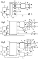
- the schematic block diagram of the known surround sound circuit from FIG. 1 contains, for example, a known one as the source 1 for spatial signals Multi-channel decoder (e.g. the processor already mentioned Dolby Surround Pro Logic " ), which delivers as output signals a right signal R, a left signal L, a middle signal C and an ambient signal S.
- Multi-channel decoder e.g. the processor already mentioned Dolby Surround Pro Logic "
- the formation of the surround sound signals from a stereo multiplex signal SM supplied by a sound intermediate frequency stage 2 takes place in a surround filter circuit 1.1
- the processing there is digital, so that the individual signals are converted back into analog signal components by means of a digital / analog converter 1.2
- a control device 3 uses control signals 3.1, 3.2 to control the source 1 and the preceding stage 2.
- Control signals 3.1 becomes the internal surround sound-F Filter circuit 1.1 switched, whereby the output signals are changed and adapted to the actual number of playback devices.
- the already mentioned phantom mode in which the center signal C is divided equally between the right and left signals R and L, has become particularly popular as the operating mode. This has no influence on the ambient signal S.
- a stereo base that is too narrow is compensated for by a modification circuit 4, which in the phantom playback mode has an input on the input side R + C " signal and one L + C " signal is fed.
- the weighting of the center signal component C is optionally frequency-dependent in the surround filter circuit 1.1.
- the output of the modification circuit 4 supplies a modified right signal R1, and a modified left signal L1, which the right or left speaker RL or
- the ambient signal S is reproduced by means of its own loudspeaker SL, which is best placed behind the listener.
- FIG. 2 A first exemplary embodiment of the invention is shown schematically in FIG. If functional units are contained in FIG. 2, which have already been described in FIG. 1, they are provided with the same reference numerals, so that there is another discussion superfluous.
- the source 1 for the spatial signals R, L, C, S can also output these as digital signals, then new digital / analog interfaces must be determined in the respective signal paths, which then have their own digital / analog converters 1.2 or use those from source 1 via separate inputs.
- the special feature of FIG. 2 is that with a reduced number of sound reproduction devices, the source 1 no longer has to be switched to the "phantom mode", but the signal reduction only takes place after the basic broadening 4.
- the center signal C is weighted by means of a multiplier 5 and added to the modified right signal R1 via a first adder 6.1 and to the demodified left signal L1 via a second adder 6.2.
- the new output signals R2 and L2 feed the right and left loudspeaker devices RL and LL.
- the weighting of the center signal C determines a multiplication factor m from the control device 3.
- Fig. 3 shows a further embodiment of the invention, in which the number of playback sources is reduced to a single pair of speakers RL, LL.
- This embodiment is particularly suitable for television receivers with a built-in right and left playback box.
- the stereo base width is relative Is small and a loudspeaker for the ambient signal is omitted, the result of the invention is a satisfactory acoustic impression.
- the circuit according to FIG. 3 differs from the circuit according to FIG. 2 in that the ambient signal S is fed to a filter circuit 7, which forms a pseudo stereo signal pair SR, SL from the ambient signal S, the right and left components of which are additive to the signal R2, L2 for the right or left loudspeaker RL, LL are added by means of a third or fourth adder 6.3, 6.4.
- the order or summary 6.5, 6.6 of the adders in each signal path to form a right signal R3 or left signal L3 is arbitrary.
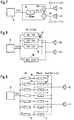
- the filter circuit 7 for forming a pair of pseudo stereo signals SR, SL from a single spatial signal component S can be very simple, cf. Fig. 7.
- the circuit shown is known and is from the publication of Audio Engineering Society " ,” Stereophonic Techniques - An anthology of reprinted articles an stereophonic techniques ", New York, 1986, pages 64 to 69. It is a reprint of an article from JAES, Volume 6, No. 2, pages 74 to 79 , April 1958 "An Artifitial Stereophonic Effect Obtained from a Single Audio Signal" by MR Schroeder.
- the improved circuitry of FIGS. 8 and 9 is also described in the same technical paper.
- the directional effect for the left or right signal L1, R1 is amplified in the stereo base broadening circuit of FIG. 4 by coupling the higher frequency components, which are important for the spatial impression, in phase opposition to the other channel.
- the coupling takes place via a first or second combination stage K1, K2, the signal component filtered with a high-pass filter HP being weighted by a multiplier M by the factor k.
- the antiphase is produced in a simplified manner in that the two combiners K1, K2 are each formed by a subtractor whose subtrahend input is fed with the high-pass filtered signal from the opposing channel.
- the circuit for stereo base broadening contains an adder, the output signal L + R of which is the sum signal from the right and left signals L, R.
- the total value represents the signal component that actually contains no directional information.
- a high-pass filter HP and a multiplier M a signal component is determined and subtracted from the right R and left signal L.
- the two modified room components R1, L1 thus each contain a lower common signal component L + R, whereby the two signal sources move apart, as it were, without the actual position of the loudspeakers being changed.
- a difference signal L - R is formed from the right and left signal R, L by means of a subtractor sb.
- a high-pass filtered portion from this difference signal L-R is used to enlarge the independent left or independent right signal portion in the respective signal path in the correct phase.
- the in-phase admixture is carried out by an adder K1 or a subtractor K2.
- the independent signal components in the two signal paths are enlarged, as a result of which the stereo base width appears to be enlarged for the listener.
- FIG. 7 shows a known circuit which generates a pseudo stereo signal pair from the monaural signal f (t) of a signal source 8, which pair is reproduced via a right and left loudspeaker RL, LL.
- the output signal f (t - ⁇ ) + 1 (t) then feeds the right speaker RL.
- the output signal f (t - ⁇ ) of the delay device 9 is combined with the original signal f (t) via a subtractor K4 and forms a signal f (t - ⁇ ) - f (t) which feeds the left loudspeaker LL.
- the direction-dependent hearing impression arises from the fact that the signals modified by the delay device 9 in conjunction with the different sound propagation times to the right and left ear of the listener simulate the desired directional impression.
- FIG. 8 shows another known example of how a pseudo stereo signal pair can be formed from a monaural signal f (t) via a filter bank BP.
- the original signal f (t) is resolved into a sequence of separate frequency ranges over a large number of narrowband bandpasses 10.
- the outputs of the successive bandpasses which are numbered from 1 to 16 in FIG. 1, are alternately connected to the right and left loudspeakers RL, LL. This again creates a directional effect.
- FIGS. 7, 8 and 9 which represent only a selection of known circuits, are described in the cited literature reference as analog circuits. Their implementation in digital circuits is familiar to the person skilled in the art and brings with it the known stability advantages. For the implementation of the surround sound system, it is also irrelevant whether the entire circuit or partial areas are implemented in hardware and / or software.
Landscapes
- Physics & Mathematics (AREA)
- Engineering & Computer Science (AREA)
- Acoustics & Sound (AREA)
- Signal Processing (AREA)
- Stereophonic System (AREA)
- Reverberation, Karaoke And Other Acoustics (AREA)
- Circuit For Audible Band Transducer (AREA)
Priority Applications (5)
| Application Number | Priority Date | Filing Date | Title |
|---|---|---|---|
| EP96107860A EP0808076B1 (fr) | 1996-05-17 | 1996-05-17 | Système acoustique à effet spatial |
| DE59611450T DE59611450D1 (de) | 1996-05-17 | 1996-05-17 | Raumklangsystem |
| US08/854,922 US6122381A (en) | 1996-05-17 | 1997-05-13 | Stereophonic sound system |
| KR1019970018860A KR100437174B1 (ko) | 1996-05-17 | 1997-05-16 | 스테레오음향시스템 |
| JP9129033A JPH1094099A (ja) | 1996-05-17 | 1997-05-19 | ステレオ音響システム |
Applications Claiming Priority (1)
| Application Number | Priority Date | Filing Date | Title |
|---|---|---|---|
| EP96107860A EP0808076B1 (fr) | 1996-05-17 | 1996-05-17 | Système acoustique à effet spatial |
Publications (2)
| Publication Number | Publication Date |
|---|---|
| EP0808076A1 true EP0808076A1 (fr) | 1997-11-19 |
| EP0808076B1 EP0808076B1 (fr) | 2007-11-21 |
Family
ID=8222788
Family Applications (1)
| Application Number | Title | Priority Date | Filing Date |
|---|---|---|---|
| EP96107860A Expired - Lifetime EP0808076B1 (fr) | 1996-05-17 | 1996-05-17 | Système acoustique à effet spatial |
Country Status (5)
| Country | Link |
|---|---|
| US (1) | US6122381A (fr) |
| EP (1) | EP0808076B1 (fr) |
| JP (1) | JPH1094099A (fr) |
| KR (1) | KR100437174B1 (fr) |
| DE (1) | DE59611450D1 (fr) |
Cited By (3)
| Publication number | Priority date | Publication date | Assignee | Title |
|---|---|---|---|---|
| RU2364053C2 (ru) * | 2003-10-27 | 2009-08-10 | Британия Инвестмент Корпорейшн | Многоканальный окружающий звук от фронтально установленных громкоговорителей |
| DE102021203632A1 (de) | 2021-04-13 | 2022-10-13 | Kaetel Systems Gmbh | Lautsprecher, Signalprozessor, Verfahren zum Herstellen des Lautsprechers oder Verfahren zum Betreiben des Signalprozessors unter Verwendung einer Dual-Mode-Signalerzeugung mit zwei Schallerzeugern |
| DE102021203639A1 (de) | 2021-04-13 | 2022-10-13 | Kaetel Systems Gmbh | Lautsprechersystem, Verfahren zum Herstellen des Lautsprechersystems, Beschallungsanlage für einen Vorführbereich und Vorführbereich |
Families Citing this family (15)
| Publication number | Priority date | Publication date | Assignee | Title |
|---|---|---|---|---|
| US6647119B1 (en) * | 1998-06-29 | 2003-11-11 | Microsoft Corporation | Spacialization of audio with visual cues |
| US6590983B1 (en) * | 1998-10-13 | 2003-07-08 | Srs Labs, Inc. | Apparatus and method for synthesizing pseudo-stereophonic outputs from a monophonic input |
| JP4300380B2 (ja) * | 1999-12-02 | 2009-07-22 | ソニー株式会社 | オーディオ再生装置およびオーディオ再生方法 |
| MXPA01011426A (es) * | 1999-05-13 | 2002-06-04 | Thomson Licensing Sa | Centralizacion de una imagen de audio estereofonica expandida en forma espacial. |
| US6879952B2 (en) | 2000-04-26 | 2005-04-12 | Microsoft Corporation | Sound source separation using convolutional mixing and a priori sound source knowledge |
| US7136493B2 (en) * | 2000-06-28 | 2006-11-14 | Peavey Electronics Corporation | Sub-harmonic generator and stereo expansion processor |
| US7451006B2 (en) * | 2001-05-07 | 2008-11-11 | Harman International Industries, Incorporated | Sound processing system using distortion limiting techniques |
| US6804565B2 (en) * | 2001-05-07 | 2004-10-12 | Harman International Industries, Incorporated | Data-driven software architecture for digital sound processing and equalization |
| US7447321B2 (en) | 2001-05-07 | 2008-11-04 | Harman International Industries, Incorporated | Sound processing system for configuration of audio signals in a vehicle |
| CA2773294C (fr) * | 2002-05-03 | 2013-03-12 | Harman International Industries, Incorporated | Systeme de detection et de localisation sonore |
| US7242779B2 (en) * | 2002-05-30 | 2007-07-10 | Peavey Electronics Corporation | Methods and apparatus for sub-harmonic generation, stereo expansion and distortion |
| JP2004166033A (ja) * | 2002-11-14 | 2004-06-10 | Victor Co Of Japan Ltd | オーディオ・エフェクタ回路 |
| US8363865B1 (en) | 2004-05-24 | 2013-01-29 | Heather Bottum | Multiple channel sound system using multi-speaker arrays |
| EP2120486A1 (fr) | 2008-05-16 | 2009-11-18 | Micronas GmbH | Dispositif et procédé destinés à produire un son spatial |
| US9100766B2 (en) * | 2009-10-05 | 2015-08-04 | Harman International Industries, Inc. | Multichannel audio system having audio channel compensation |
Citations (3)
| Publication number | Priority date | Publication date | Assignee | Title |
|---|---|---|---|---|
| DE4030121A1 (de) * | 1989-10-11 | 1991-04-25 | Mitsubishi Electric Corp | Mehrkanal-audiowiedergabevorrichtung und -verfahren |
| EP0608930A1 (fr) * | 1993-01-22 | 1994-08-03 | Koninklijke Philips Electronics N.V. | Transmission numérique à trois canaux de signaux/stéreohoniques gauche et droit et d'un signal central |
| EP0630168A1 (fr) * | 1993-06-15 | 1994-12-21 | NOKIA TECHNOLOGY GmbH | Décodeur prologic Dolby |
Family Cites Families (5)
| Publication number | Priority date | Publication date | Assignee | Title |
|---|---|---|---|---|
| CA942198A (en) * | 1970-09-15 | 1974-02-19 | Kazuho Ohta | Multidimensional stereophonic reproducing system |
| JPS56130400U (fr) * | 1980-03-04 | 1981-10-03 | ||
| US5412731A (en) * | 1982-11-08 | 1995-05-02 | Desper Products, Inc. | Automatic stereophonic manipulation system and apparatus for image enhancement |
| KR920020952A (ko) * | 1991-04-17 | 1992-11-21 | 이헌조 | 써라운드 모드 자동 절환 회로 |
| DE69433258T2 (de) * | 1993-07-30 | 2004-07-01 | Victor Company of Japan, Ltd., Yokohama | Raumklangsignalverarbeitungsvorrichtung |
-
1996
- 1996-05-17 EP EP96107860A patent/EP0808076B1/fr not_active Expired - Lifetime
- 1996-05-17 DE DE59611450T patent/DE59611450D1/de not_active Expired - Lifetime
-
1997
- 1997-05-13 US US08/854,922 patent/US6122381A/en not_active Expired - Lifetime
- 1997-05-16 KR KR1019970018860A patent/KR100437174B1/ko not_active Expired - Fee Related
- 1997-05-19 JP JP9129033A patent/JPH1094099A/ja not_active Withdrawn
Patent Citations (3)
| Publication number | Priority date | Publication date | Assignee | Title |
|---|---|---|---|---|
| DE4030121A1 (de) * | 1989-10-11 | 1991-04-25 | Mitsubishi Electric Corp | Mehrkanal-audiowiedergabevorrichtung und -verfahren |
| EP0608930A1 (fr) * | 1993-01-22 | 1994-08-03 | Koninklijke Philips Electronics N.V. | Transmission numérique à trois canaux de signaux/stéreohoniques gauche et droit et d'un signal central |
| EP0630168A1 (fr) * | 1993-06-15 | 1994-12-21 | NOKIA TECHNOLOGY GmbH | Décodeur prologic Dolby |
Non-Patent Citations (1)
| Title |
|---|
| M.R.SCHROEDER: "AN ARTIFICIAL STEREOPHONIC EFFECT OBTAINED FROM A SINGLE AUDIO SIGNAL.", JOURNAL OF THE AUDIO ENGINEERING SOCIETY, vol. 6, no. 2, April 1958 (1958-04-01), pages 74 - 79, XP000604521 * |
Cited By (4)
| Publication number | Priority date | Publication date | Assignee | Title |
|---|---|---|---|---|
| RU2364053C2 (ru) * | 2003-10-27 | 2009-08-10 | Британия Инвестмент Корпорейшн | Многоканальный окружающий звук от фронтально установленных громкоговорителей |
| DE102021203632A1 (de) | 2021-04-13 | 2022-10-13 | Kaetel Systems Gmbh | Lautsprecher, Signalprozessor, Verfahren zum Herstellen des Lautsprechers oder Verfahren zum Betreiben des Signalprozessors unter Verwendung einer Dual-Mode-Signalerzeugung mit zwei Schallerzeugern |
| DE102021203639A1 (de) | 2021-04-13 | 2022-10-13 | Kaetel Systems Gmbh | Lautsprechersystem, Verfahren zum Herstellen des Lautsprechersystems, Beschallungsanlage für einen Vorführbereich und Vorführbereich |
| US12556863B2 (en) | 2021-04-13 | 2026-02-17 | Kaetel Systems Gmbh | Loudspeaker, signal processor, method for manufacturing the loudspeaker, or method for operating the signal processor by using dual-mode signal generation with two sound generators |
Also Published As
| Publication number | Publication date |
|---|---|
| US6122381A (en) | 2000-09-19 |
| DE59611450D1 (de) | 2008-01-03 |
| JPH1094099A (ja) | 1998-04-10 |
| KR100437174B1 (ko) | 2004-09-07 |
| EP0808076B1 (fr) | 2007-11-21 |
| KR970078741A (ko) | 1997-12-12 |
Similar Documents
| Publication | Publication Date | Title |
|---|---|---|
| EP0808076B1 (fr) | Système acoustique à effet spatial | |
| DE69433258T2 (de) | Raumklangsignalverarbeitungsvorrichtung | |
| DE2616762C2 (de) | Einrichtung zur Aufweitung eines stereophonen Klangbildes | |
| DE69924896T2 (de) | Vorrichtung und Verfahren zur Schallbildlokalisierung | |
| DE112008003305B4 (de) | Bandaufteilungs-Zeitausgleich-Signalverarbeitungs-Vorrichtung | |
| DE4134130C2 (de) | Vorrichtung zum Aufweiten und Ausbalancieren von Schallfeldern | |
| DE19715498B4 (de) | Stereoklangbildverbesserungsvorrichtungen und -verfahren unter Verwendung von Tabellen | |
| DE69717678T2 (de) | Stereotonerweiterer | |
| DE2806914A1 (de) | Tonwiedergabesystem | |
| DE3519644A1 (de) | Verfahren und vorrichtung zur tonwiedergabe mit einem realistischen raumklangeindruck | |
| DE2720984B2 (fr) | ||
| DE69533211T2 (de) | Signalkombinationsschaltung für stereophonische Wiedergabe mit Quersignalkoppelung | |
| DE3040896C2 (de) | Schaltungsanordnung zur Erzeugung und Aufbereitung stereophoner Signale aus einem monophonen Signal | |
| DE4136022A1 (de) | Vorrichtung zum ausweiten und steuern von schallfeldern | |
| DE69227091T2 (de) | Schaltung zur Mischung und Verdoppelung von niedrigen Tonfrequenzen | |
| DE69834466T2 (de) | Vorrichtung und Verfahren zur Schallbildlokalisierung | |
| DE102006027673A1 (de) | Signaltrenner, Verfahren zum Bestimmen von Ausgangssignalen basierend auf Mikrophonsignalen und Computerprogramm | |
| DE2627437A1 (de) | Quadrophoniesystem | |
| EP2499843B1 (fr) | Procédé pour mélanger des signaux des microphones d'une reproduction utilisant des plusieurs microphones | |
| WO2015049334A1 (fr) | Procédé et dispositif de downmixage d'un signal multicanaux et d'upmixage d'un signal downmixé | |
| EP2939445B1 (fr) | Production de signaux audio 3d | |
| DE19632734A1 (de) | Verfahren und Vorrichtung zum Generieren eines Mehrton-Signals aus einem Mono-Signal | |
| DE102015222105A1 (de) | Audiosignalverarbeitung in einem Fahrzeug | |
| DE102004053790A1 (de) | Verfahren zur Erzeugung von Stereosignalen für getrennte Quellen und entsprechendes Akustiksystem | |
| EP0776144B1 (fr) | Circuit pour la modification d'un signal |
Legal Events
| Date | Code | Title | Description |
|---|---|---|---|
| PUAI | Public reference made under article 153(3) epc to a published international application that has entered the european phase |
Free format text: ORIGINAL CODE: 0009012 |
|
| AK | Designated contracting states |
Kind code of ref document: A1 Designated state(s): DE FR GB IT NL |
|
| RAP1 | Party data changed (applicant data changed or rights of an application transferred) |
Owner name: MICRONAS INTERMETALL GMBH |
|
| 17P | Request for examination filed |
Effective date: 19980519 |
|
| RAP1 | Party data changed (applicant data changed or rights of an application transferred) |
Owner name: MICRONAS GMBH |
|
| GRAP | Despatch of communication of intention to grant a patent |
Free format text: ORIGINAL CODE: EPIDOSNIGR1 |
|
| RTI1 | Title (correction) |
Free format text: SURROUND SOUND SYSTEM |
|
| GRAS | Grant fee paid |
Free format text: ORIGINAL CODE: EPIDOSNIGR3 |
|
| GRAA | (expected) grant |
Free format text: ORIGINAL CODE: 0009210 |
|
| AK | Designated contracting states |
Kind code of ref document: B1 Designated state(s): DE FR GB IT NL |
|
| REG | Reference to a national code |
Ref country code: GB Ref legal event code: FG4D Free format text: NOT ENGLISH |
|
| REF | Corresponds to: |
Ref document number: 59611450 Country of ref document: DE Date of ref document: 20080103 Kind code of ref document: P |
|
| GBT | Gb: translation of ep patent filed (gb section 77(6)(a)/1977) |
Effective date: 20080124 |
|
| ET | Fr: translation filed | ||
| PLBE | No opposition filed within time limit |
Free format text: ORIGINAL CODE: 0009261 |
|
| STAA | Information on the status of an ep patent application or granted ep patent |
Free format text: STATUS: NO OPPOSITION FILED WITHIN TIME LIMIT |
|
| 26N | No opposition filed |
Effective date: 20080822 |
|
| PGFP | Annual fee paid to national office [announced via postgrant information from national office to epo] |
Ref country code: FR Payment date: 20100601 Year of fee payment: 15 |
|
| PGFP | Annual fee paid to national office [announced via postgrant information from national office to epo] |
Ref country code: NL Payment date: 20100524 Year of fee payment: 15 Ref country code: IT Payment date: 20100527 Year of fee payment: 15 |
|
| REG | Reference to a national code |
Ref country code: NL Ref legal event code: SD Effective date: 20101011 |
|
| PGFP | Annual fee paid to national office [announced via postgrant information from national office to epo] |
Ref country code: GB Payment date: 20100525 Year of fee payment: 15 |
|
| REG | Reference to a national code |
Ref country code: GB Ref legal event code: 732E Free format text: REGISTERED BETWEEN 20101125 AND 20101201 |
|
| REG | Reference to a national code |
Ref country code: FR Ref legal event code: TP |
|
| REG | Reference to a national code |
Ref country code: DE Ref legal event code: R081 Ref document number: 59611450 Country of ref document: DE Owner name: ENTROPIC COMMUNICATIONS, INC., SAN DIEGO, US Free format text: FORMER OWNER: MICRONAS GMBH, 79108 FREIBURG, DE Effective date: 20110210 |
|
| REG | Reference to a national code |
Ref country code: NL Ref legal event code: V1 Effective date: 20111201 |
|
| GBPC | Gb: european patent ceased through non-payment of renewal fee |
Effective date: 20110517 |
|
| PG25 | Lapsed in a contracting state [announced via postgrant information from national office to epo] |
Ref country code: NL Free format text: LAPSE BECAUSE OF NON-PAYMENT OF DUE FEES Effective date: 20111201 |
|
| REG | Reference to a national code |
Ref country code: FR Ref legal event code: ST Effective date: 20120131 |
|
| PG25 | Lapsed in a contracting state [announced via postgrant information from national office to epo] |
Ref country code: IT Free format text: LAPSE BECAUSE OF NON-PAYMENT OF DUE FEES Effective date: 20110517 |
|
| REG | Reference to a national code |
Ref country code: DE Ref legal event code: R084 Ref document number: 59611450 Country of ref document: DE Effective date: 20110426 |
|
| PG25 | Lapsed in a contracting state [announced via postgrant information from national office to epo] |
Ref country code: FR Free format text: LAPSE BECAUSE OF NON-PAYMENT OF DUE FEES Effective date: 20110531 |
|
| PG25 | Lapsed in a contracting state [announced via postgrant information from national office to epo] |
Ref country code: GB Free format text: LAPSE BECAUSE OF NON-PAYMENT OF DUE FEES Effective date: 20110517 |
|
| REG | Reference to a national code |
Ref country code: DE Ref legal event code: R082 Ref document number: 59611450 Country of ref document: DE Representative=s name: EPPING HERMANN FISCHER, PATENTANWALTSGESELLSCH, DE |
|
| REG | Reference to a national code |
Ref country code: DE Ref legal event code: R082 Ref document number: 59611450 Country of ref document: DE Representative=s name: EPPING HERMANN FISCHER, PATENTANWALTSGESELLSCH, DE Effective date: 20121023 Ref country code: DE Ref legal event code: R081 Ref document number: 59611450 Country of ref document: DE Owner name: ENTROPIC COMMUNICATIONS, INC., SAN DIEGO, US Free format text: FORMER OWNER: TRIDENT MICROSYSTEMS (FAR EAST) LTD., GRAND CAYMAN, KY Effective date: 20121023 Ref country code: DE Ref legal event code: R081 Ref document number: 59611450 Country of ref document: DE Owner name: ENTROPIC COMMUNICATIONS, INC., US Free format text: FORMER OWNER: TRIDENT MICROSYSTEMS (FAR EAST) LTD., GRAND CAYMAN, KY Effective date: 20121023 |
|
| PGFP | Annual fee paid to national office [announced via postgrant information from national office to epo] |
Ref country code: DE Payment date: 20130530 Year of fee payment: 18 |
|
| REG | Reference to a national code |
Ref country code: DE Ref legal event code: R119 Ref document number: 59611450 Country of ref document: DE |
|
| REG | Reference to a national code |
Ref country code: DE Ref legal event code: R119 Ref document number: 59611450 Country of ref document: DE Effective date: 20141202 |
|
| PG25 | Lapsed in a contracting state [announced via postgrant information from national office to epo] |
Ref country code: DE Free format text: LAPSE BECAUSE OF NON-PAYMENT OF DUE FEES Effective date: 20141202 |