EP0808410B1 - Appareil permettant de determiner la courbure d'un orifice allonge tel qu'un forage, par exemple dans la roche - Google Patents
Appareil permettant de determiner la courbure d'un orifice allonge tel qu'un forage, par exemple dans la roche Download PDFInfo
- Publication number
- EP0808410B1 EP0808410B1 EP96903282A EP96903282A EP0808410B1 EP 0808410 B1 EP0808410 B1 EP 0808410B1 EP 96903282 A EP96903282 A EP 96903282A EP 96903282 A EP96903282 A EP 96903282A EP 0808410 B1 EP0808410 B1 EP 0808410B1
- Authority
- EP
- European Patent Office
- Prior art keywords
- probe
- curvature
- channel
- optical fibre
- fibre section
- Prior art date
- Legal status (The legal status is an assumption and is not a legal conclusion. Google has not performed a legal analysis and makes no representation as to the accuracy of the status listed.)
- Expired - Lifetime
Links
- 239000011435 rock Substances 0.000 title claims abstract description 8
- 239000000523 sample Substances 0.000 claims abstract description 123
- 239000013307 optical fiber Substances 0.000 claims abstract description 47
- 239000000835 fiber Substances 0.000 claims abstract description 41
- 238000005452 bending Methods 0.000 claims abstract description 30
- 230000008859 change Effects 0.000 claims abstract description 16
- 238000005259 measurement Methods 0.000 claims abstract description 10
- 230000007935 neutral effect Effects 0.000 claims abstract description 7
- 238000000034 method Methods 0.000 claims description 16
- 230000003287 optical effect Effects 0.000 claims description 12
- 230000005484 gravity Effects 0.000 claims description 2
- 230000008901 benefit Effects 0.000 description 7
- 230000001419 dependent effect Effects 0.000 description 6
- 238000012360 testing method Methods 0.000 description 6
- 230000015572 biosynthetic process Effects 0.000 description 5
- 238000005755 formation reaction Methods 0.000 description 5
- 230000008569 process Effects 0.000 description 5
- 238000012545 processing Methods 0.000 description 4
- 230000001681 protective effect Effects 0.000 description 4
- 238000001514 detection method Methods 0.000 description 3
- GWEVSGVZZGPLCZ-UHFFFAOYSA-N Titan oxide Chemical compound O=[Ti]=O GWEVSGVZZGPLCZ-UHFFFAOYSA-N 0.000 description 2
- 238000010276 construction Methods 0.000 description 2
- 238000006073 displacement reaction Methods 0.000 description 2
- 238000005553 drilling Methods 0.000 description 2
- 230000002349 favourable effect Effects 0.000 description 2
- 238000005305 interferometry Methods 0.000 description 2
- 238000004519 manufacturing process Methods 0.000 description 2
- 238000013507 mapping Methods 0.000 description 2
- 238000012544 monitoring process Methods 0.000 description 2
- 238000004181 pedogenesis Methods 0.000 description 2
- 230000000737 periodic effect Effects 0.000 description 2
- 125000006850 spacer group Chemical group 0.000 description 2
- 230000003595 spectral effect Effects 0.000 description 2
- 229910001369 Brass Inorganic materials 0.000 description 1
- 238000009412 basement excavation Methods 0.000 description 1
- 238000005422 blasting Methods 0.000 description 1
- 239000010951 brass Substances 0.000 description 1
- 238000005253 cladding Methods 0.000 description 1
- 230000001427 coherent effect Effects 0.000 description 1
- 230000000295 complement effect Effects 0.000 description 1
- 239000002131 composite material Substances 0.000 description 1
- 230000008878 coupling Effects 0.000 description 1
- 238000010168 coupling process Methods 0.000 description 1
- 238000005859 coupling reaction Methods 0.000 description 1
- 230000008021 deposition Effects 0.000 description 1
- 238000009826 distribution Methods 0.000 description 1
- 239000011152 fibreglass Substances 0.000 description 1
- 238000009434 installation Methods 0.000 description 1
- 230000002452 interceptive effect Effects 0.000 description 1
- 238000012821 model calculation Methods 0.000 description 1
- 238000012986 modification Methods 0.000 description 1
- 230000004048 modification Effects 0.000 description 1
- 230000010363 phase shift Effects 0.000 description 1
- 230000035945 sensitivity Effects 0.000 description 1
- 238000003466 welding Methods 0.000 description 1
Images
Classifications
-
- G—PHYSICS
- G01—MEASURING; TESTING
- G01B—MEASURING LENGTH, THICKNESS OR SIMILAR LINEAR DIMENSIONS; MEASURING ANGLES; MEASURING AREAS; MEASURING IRREGULARITIES OF SURFACES OR CONTOURS
- G01B11/00—Measuring arrangements characterised by the use of optical techniques
- G01B11/16—Measuring arrangements characterised by the use of optical techniques for measuring the deformation in a solid, e.g. optical strain gauge
- G01B11/18—Measuring arrangements characterised by the use of optical techniques for measuring the deformation in a solid, e.g. optical strain gauge using photoelastic elements
-
- E—FIXED CONSTRUCTIONS
- E21—EARTH OR ROCK DRILLING; MINING
- E21B—EARTH OR ROCK DRILLING; OBTAINING OIL, GAS, WATER, SOLUBLE OR MELTABLE MATERIALS OR A SLURRY OF MINERALS FROM WELLS
- E21B47/00—Survey of boreholes or wells
- E21B47/02—Determining slope or direction
- E21B47/022—Determining slope or direction of the borehole, e.g. using geomagnetism
-
- G—PHYSICS
- G01—MEASURING; TESTING
- G01B—MEASURING LENGTH, THICKNESS OR SIMILAR LINEAR DIMENSIONS; MEASURING ANGLES; MEASURING AREAS; MEASURING IRREGULARITIES OF SURFACES OR CONTOURS
- G01B11/00—Measuring arrangements characterised by the use of optical techniques
- G01B11/24—Measuring arrangements characterised by the use of optical techniques for measuring contours or curvatures
Definitions
- the invention relates to apparatus of the kind defined in the preamble of Claim 1.
- Apparatus of this kind find use in ore prospecting operations and in investigating and mapping ore deposits and other types of deposits. It is, of course, important when investigating ore deposits for instance, to be aware of the actual directional extension of the test holes that are drilled to this end, for instance the location of the hole at different depths, in order to effectively map the deposits. Such drill holes will always have curved sections and it is therefore necessary to determine the actual longitudinal extension of the drill hole.
- an apparatus of the kind taught by SE-C-387698 (7304122-0) wherein an apparatus probe is moved to different longitudinal sections of the hole and is constructed to conform to the curvature of the hole. Curvature or bending of the probe is determined with the aid of a camera which observes an objective in the probe, wherein the relative transversal displacement of the objective caused by curving of the probe constitutes a measurement of the curvature of the drill hole.
- the known probe In order to provide an accurate measuring result and, at the same time, to minimize the total cost of the preliminary exploration, the known probe must have a relatively large diameter. Naturally, the diameter of the test drill hole must be correspondingly large, and it is well known that the cost of drilling the test hole increases with increasing hole diameters.
- a further object of the invention is to provide an apparatus which is very flexible, magnetically insensitive, production friendly and temperature independent and which enables measurements to be made at several points along the probe in a simple manner.
- the invention is not restricted solely to determining the longitudinal extension of drill holes in rock, but can be used more generally to determine the curvature of any form of channel or passageway.
- a channel or passageway may conceivably have the form of a slot, wherein the actual probe may be rigid in the width direction of the slot when it is essentially only necessary to obtain information regarding curvature of the slot solely in a plane at right angles to the width direction of the slot.
- an optic fibre section is fitted in or on the probe body at a distance from its bending neutral line, preferably close to the outer surface of the probe body.
- the optical fibre section is mounted in the length direction of the probe. Consequently, as the probe bends, the optical fibre section will be subjected to a change in length that is representative of the extent to which the probe bends in an axial plane embraced by the optical fibre section and the probe axis.
- probe axis is meant its bending neutral line, i.e. the centres of gravity of respective probe cross-section areas.
- the channel curvature is evaluated by calculating the physical change in distance between two partial reflection devices (e.g.
- the curvature is measured optically such that the measuring result will comprise primarily the optical change in distance between the partial reflection devices. It is important to note that this optical change in distance does not solely correspond to the physical change in distance but is also influenced by the fact that the optical properties of the fibre, such as refractive index, are also affected by the physical bending of the fibre. Because the optical fibre sections have separate partial reflection devices, changes in length of the optical fibre section between the reflection devices as a result of bending of the section in the axial plane through the probe in which the section lies can be measured interferometrically.
- curvature of the channel results in changes in the core of the optical fibre used, which in turn results in an "electromagnetic signature" that can be measured.
- the use of two fibre sections in different axial planes thus enables bending of the probe and the position of the bend around the probe axis to be calculated.
- the two axial planes may conveniently be separated through an angle of 90°, for instance.
- the probe body is also influenced by shear stresses in the presence of large stretching forces.
- US-A-4,927,232 discloses a non-related technique of monitoring a buried pipeline with regard to ground movements with the aid of an optical fibre on the surface of the pipeline along the length thereof.
- the core of the optical fibre is surrounded by cladding which when subjected to radial forces changes the "electrooptic signature" of the optical fibre, such that an indication of a change in the radial forces acting on the pipeline can be obtained by measuring such changes in the electrooptic signature" of the optical fibre.
- US-A-4,806,012 describes an optical fibre strain gauge.
- the optical fibre is attached to or embedded in a structure, for instance a plate, which is to be monitored with regard to strain distribution along the fibre.
- the core string of the optical fibre is provided with different grating formations along its length.
- the spacing between the grating lines in the grating will change so as to cause a change in the reflection wavelength of the grating and thereby enable the strain acting in the various grating formations to be measured optically.
- An optical fibre strain gauge of this kind has relatively low sensitivity.
- Fizeau interferometer which in principle comprises an optical fibre having longitudinally spaced partial reflection devices, for instance gratings, so as to enable strain acting in the fibre to be determined interferometrically, by detecting the changes in length of the fibre between two gratings.
- the probe of the inventive apparatus may be made thin, which is highly significant in reducing the cost of tests drilling, for instance in mapping a deposit, such as an ore deposit.
- An important advantage of using an optical fibre in accordance with the invention is that the actual sensor part of the apparatus may be included as a permanent installation that has a sufficiently long length of life, at reasonable cost. For instance, it is of interest to be able to monitor regularly movements and displacements in rock formations and earth strata over relatively long time periods, for instance in the construction of large dams and roads, by moving the probe to mutually sequential longitudinal sections of drill holes therein and measuring the curvature of the drill holes. The relatively much more expensive signal processing part of the equipment can then be connected temporarily to the sensor, when the actual measuring process is to take place.
- a long row of sensor elements (each comprising an optical fibre section having two separate gratings, for instance) can be multiplexed on one single fibre. This enables the construction of a probe/sensor which is able to measure curvature at a large number of locations along a long distance. Because a large number of sensors are multiplexed on a long sensor/probe and because the different sensor elements use different gratings, measurements can be effected much more quickly than was earlier possible. A measuring process effected in accordance with the known technique is much more laborious.
- Multiplexing can be utilized for measuring, for instance, the path difference or the time difference between incoming light and light reflected from gratings, when said gratings are identical but located at different positions along the optical fibre.
- multiplexing can be based on different reflection wavelenghts for grating of mutually different frequencies.
- optical fibre sections having mutually spaced reflection means such as mirrors in an interferometer, is that it enables a measuring distance to be defined along which the mean value of the curvature is obtained. This avoids the problem of local inhomogeneities.
- fibre gratings can be mass-produced. This enables gratings to be produced in the fibre (enables gratings to be written into the fibre) at a large number of locations along an optical fibre, which may have a length measured in kilometers, at relatively low extra cost.
- the gratings may be formed by exposing the fibre interferometrically with UV light. In the production of a sensor within the scope of the present invention, the sensor part can thereby be produced at very low cost.
- the probe may be much shorter than the channel whose curvature/ longitudinal extension is to be determined, wherein the probe is moved to different positions along the length of the channel, wherein the curvature of the channel is registered at said different positions, and wherein the rotational position of the probe in said different positions is also conveniently registered.
- partial reflection means e.g. gratings
- the probe may be provided with gratings/reflection means in a plurality or multiple of axially separated positions along the strain sensing optical fibres, so as to enable curvature to be measured in many different axial positions along the probe and along the channel with the same distance requirement between the curvature measuring points and without needing to move the actual probe axially.
- the probe may be configured with a multiple of partial reflection means, for instance several thousand reflection means or pairs thereof at separate locations along the optical fibre/optical fibres of the probe, so as to enable the probe to be manufactured in lengths of up to several thousand metres.
- Such monitoring systems find use, for instance, in tunnel excavating work and like work, wherein one or more test holes are drilled along but outside said tunnel extension, and wherein long inventive probes can be inserted into these test holes and left therein so as to be able to establish the occurrence of changes by frequently determining curvature of the probe, and the magnitude of or the danger presented by these changes in connection with and due to continued excavation/blasting of the tunnel, so as to enable necessary countermeasures to be taken before the risks of or the disadvantages of the change in curvature/settling of the ground reaches a dangerous state.
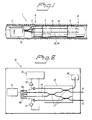
- the probe 1 comprises protective tubing 4, for instance brass tubing or tubing comprised of a fiber-glass composite, which although being rigid is sufficiently flexible to enable the tubing to conform to the same curvature as that of a drill hole into which the probe is inserted.
- the probe has essentially the same diameter as the drill hole, so that the probe will closely follow the curvature of said hole.
- the probe includes a probe body 3 which in the present case is comprised of a flexible, circular-cylindrical rod in the form of a thick-walled pipe whose inner and outer diameters are known.
- the probe body 3 is held concentrically in the protective tubing 4 by means of tubular spacer elements 5.
- the spacer elements 5 may have the form of slide bearings which enable the probe body 3 to rotate relative to the protective tubing 4.
- Optical fibres 31-34 are attached to the cylindrical probe body 3, for instance embedded therein or glued thereto. The fibres are fastened on/in the body 3 in a manner such that the fibres will bend when the body is subjected to strain.
- the fibres 31-34 extend parallel with the bending neutral line of the body, wherein each of the fibres is spaced at a constant distance along its length from the axis of the body 3 (the bending neutral line of the body) along its measuring distance.
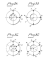
- Fig. 3A can be considered as being a cross-sectional view of the tubular probe body 3 of Fig. 1, and it can be seen from Fig. 3A that the fibres 31 and 32 lie respectively on the inner surface and the outer surface of the body 3 in an axial plane 41 of the body 3 that extends through its neutral bending axis 44.
- the fibres 33 and 34 lie in an axial plane 42 of the body 3, these planes 41, 42 being mutually separated, preferably through an angle of 90°.
- the fibres lie in respective axial planes on the same side of the axis 44.
- fibres 31-34 are connected to a signal processing unit.
- Each of the optical fibres includes a partial reflection means 8a, 8b, 22a, 22b disposed at two predetermined positions A and B respectively along the body 3.
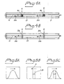
- said partial reflection means may comprise respective fibre gratings 8a and 8b.
- Incoming light 19 is reflected partially by the grating 8a and gives rise to an oppositely directed beam of light 20a, and the other grating 8b gives rise to an oppositely directed beam of light 20b in a similar manner, wherein part of the light is transmitted as indicated at 21.
- partially reflecting mirrors 22a and 22b can be incorporated in the fibres at respective positions A and B, for instance by severing the optical fibre and then applying a layer of, e.g., TiO 2 by vapour deposition on the cut surfaces, and thereafter welding the fibre ends together so that the vapour-deposited layer will establish a partially reflecting mirror.
- a layer of, e.g., TiO 2 by vapour deposition on the cut surfaces, and thereafter welding the fibre ends together so that the vapour-deposited layer will establish a partially reflecting mirror.
- light from the light sources 9a, 9b is conducted through optical fibres 15 to an optical chip 16, where the light is distributed to the sensor fibres 31, 32 through the medium of a plurality of waveguide switches or couplers 17.
- the light 19 returns as signals 20a, 20b which are re-distributed to the detectors 11 by the chip 16 and thereafter amplified in respective amplifier stages 12, as shown in Fig. 4A.
- the resultant signal is finally processed electronically in the processor 13.
- the light sources 9a, 9b are driven with the aid of control electronics 14, which ensure that the wavelength of the laser light source is held constant, with the aid of a reference grating 18.
- the fibre gratings 8a, 8b have a broad spectral characteristic in relation to the light source 9.
- the pair of gratings 8a, 8b will function as a pair of mirrors in the fibre when the wavelength of the light source 9 is chosen close to the central wavelength of the gratings 8a, 8b.
- the two reflection means, the gratings 8a, and the fibre form a so-called Fizeau interferometer.
- the phase position between the two reflected light beams 20a, 20b is linearly dependent on the distance between the gratings 8a, 8b and thereby linearly dependent on strain acting on the optical fibre.
- the phase difference thus reflects the bending of the probe body 3 between the pair of gratings.
- the two reflected light beams 20a, 20b are thus led back to the detector 10, where they are allowed to interfere.
- the length of coherence of the light source will preferably be greater than twice the distance between the gratings 8a, 8b.
- the processor 13 functions to produce a bending measurement value.
- the detected signal is sinusoidally dependent on the phase difference (interference fringes) and the processing of the signals is mainly to count the interference fringes and to check the location of the interference fringes.
- One way is to use two wavelength interferometry. As the name implies, two wavelengths are then required, these wavelengths either being obtained by using two mutually independent light sources 9a, 9b (c.f. Fig. 2) or by using a light source which can be tuned with respect to wavelength, so as to achieve a corresponding function.
- Another method is to use one of the gratings 8a, 8b included in the Fizeau interferometer, and particularly the spectral characteristics of the grating.
- a tunable light source or by using spectroscopic detection, i.e. wavelength-dependent detection, it is possible, for instance, to establish the central wavelength of the grating.
- the central wavelength is thus the strain-dependent wavelength, and an absolute value of fibre bending can be established by measuring this central wavelength.
- this method is not as accurate as the interferometric method, but can be used to provide an approximate starting value.
- the method may be used advantageously in combination with two wavelength interferometry to obtain extremely accurate measurements of the absolute value of the strain in the fibre.
- Fig. 3B can be considered to show that the fibre sections 32 and 34 have been moved parallel to one another in their respective axial planes 41, 42, to the region of the outer surface of the probe body 3. All of the active fibre sections 31-34 will hereby be located at the greatest possible distance from the axis 44, thereby enabling the diameter of the probe body to be minimized.
- a further pair of fibre sections 35, 36 are disposed in an axial plane 43 comprising the axis 44, wherein the fibres 35, 36 lie parallel with and along the generatrices of the body 3.
- the three pairs of fibre sections 31, 32; 33, 34; 35, 36 are disposed in equidistantly spaced planes.
- the additional information obtained by the sensors 35, 36 in the "third" axial plane can be used for compensating any errors that may occur as a result of shear stresses generated when the sensor body is subjected to heavy bending, i.e. is given a relatively small radius of curvature.
- strain sensing optical fibre sections lie in at least two angularly separated axial planes that extend through the bending mutual line of the probe, so as to enable bending/curvature of the probe to be measured in three dimensions.
- An additional fibre section/Fizeau interferometer has been included to provide temperature compensation of the measuring signal.
- the probe body 3 need not necessarily be rotational symmetrical. It may be so that it is known beforehand that the curvature of the channel to be measured will be much greater in one certain plane than in another plane and that the probe body may be constructed accordingly, for instance so that the body can be given an elliptic cross-section.
- the probe body 3 By giving the probe body 3 a well-defined shape and by also giving the fibre sections 31, 34 a well-defined position, bending can be calculated with the aid of known models for bending beam-like objects. However, this does not exclude the possibility of obtaining the ratio between resultant signals and curvature with the aid of a calibration process instead. In certain instances, this may even be a necessary complement to the model calculations.
- Figs. 5A-C illustrate light intensity as a function of wavelength for incoming, reflected and transmitted light in a grating.
- the grating 8 is a periodic refractive index variation which has been written into the fibre core 23 by means of interfering UV light.
- a broadband light source i.e. light having a broad spectrum
- Fig. 5B When light emanating from a broadband light source, i.e. light having a broad spectrum (Fig. 5A), falls on the grating 8, only the wavelength 31 which is twice as long as the periodicity of the grating will be reflected back (Fig. 5B).
- the reflective wavelength When the grating 8 is subjected to strain, the reflective wavelength will increase and the change in wavelength 39 of reflected light will constitute a measurement of the strain.
- the phase shift between the reflected light beams or rays thus indicates strain, i.e. bending of the probe body 3. From a measuring technical aspect, such a phase difference can only be established by coherent detection.
- the illustrated embodiment illustrates a measuring process based on reflected light
- the measuring process can equally as well be carried out on the basis of transmitted light.
- the interferometers may, of course, be connected in series if the reflection means are constructed in accordance with known techniques such that said means and their measurement signals can be identified.
- the orientation of the sensor body (3) is not fully determined by establishing its curvature, since the probe body may rotate about its axis as it is moved through the measuring channel (the rock drill hole). Consequently, the apparatus probe will preferably be supplemented with either a gyroscope 51 or a spirit level which will provide information relating to the rotational position of the probe.
- information relating to curvature and possibly to the rotational position of the probe can be registered in the probe or transmitted conventionally over wires or fibres or by radio to a remotely operated receiver, for instance at an accessible end of the channel.
Landscapes
- Physics & Mathematics (AREA)
- General Physics & Mathematics (AREA)
- Mining & Mineral Resources (AREA)
- Life Sciences & Earth Sciences (AREA)
- Engineering & Computer Science (AREA)
- Geology (AREA)
- Fluid Mechanics (AREA)
- Environmental & Geological Engineering (AREA)
- Geophysics (AREA)
- General Life Sciences & Earth Sciences (AREA)
- Geochemistry & Mineralogy (AREA)
- Length Measuring Devices By Optical Means (AREA)
- Earth Drilling (AREA)
- Length Measuring Devices With Unspecified Measuring Means (AREA)
Claims (14)
- Appareil pour déterminer la courbure dans un canal allongé, tel qu'un trou de forage dans la roche par exemple, ledit appareil comprenant un capteur ou sonde flexible (1) qui est destiné à prendre la courbure du canal lorsqu'il est inséré dans ce canal, dans lequel le capteur (1) présente des moyens (3, 31, 10) pour mesurer la courbure du capteur et ainsi la courbure du canal, entre au moins deux positions espacées longitudinalement (A, B) sur le capteur (1), caractérisé en ce que lesdits moyens comprennent une partie de fibre optique (31) qui est connectée à un corps de capteur flexible (3) disposé dans le capteur (1) et connecté audit capteur de façon à accompagner la flexion ou l'incurvation dudit capteur, dans lequel la partie de fibre optique (31) s'étend parallèlement à et à une distance constante de l'axe neutre de flexion (44) sur le corps de capteur (3) de façon que la déformation de la partie de fibre fournisse une mesure de la flexion du corps de capteur (3) dans un plan axial (41) qui inclut la partie de fibre (31) ; en ce que la partie de fibre optique (41) présente deux moyens de réflexion partiels (8a, 8b, 22a, 22b) au niveau desdites positions (A, B) le long du capteur ; et en ce que des moyens (10) sont reliés à la partie de fibre optique pour la détermination par interférométrie de la modification de la distance entre les moyens de réflexion partiels dans la partie de fibre (31); et en ce que des moyens (32, 10) sont disposés pour compenser l'influence de la température sur la variation de distance entre les moyens de réflexion partiels.
- Appareil selon la revendication 1, caractérisé en ce que les moyens de compensation de l'influence de la température comprennent une partie de fibre optique supplémentaire (32) qui est ajoutée à la partie de fibre optique mentionnée en premier (31) et s'étend parallèlement à cette première partie de fibre optique dans le même plan axial (41), dans lequel ladite partie de fibre supplémentaire présente des moyens de réflexion partiels (8a, 8b, 22a, 22b) de préférence également au niveau desdites positions (A, B) le long du capteur, de sorte que la différence de déformation entre les deux parties de fibres optiques (31, 32) fournisse une valeur de mesure indépendante de la température de l'amplitude de la flexion du capteur dans le plan axial.
- Appareil selon la revendication 1 ou la revendication 2, caractérisé en ce que la distance entre les positions de capteurs (A, B) vaut au moins dix fois le rayon du corps de capteur (3) au niveau de la partie de fibre optique mesurant la déformation la plus à l'intérieur radialement (32); et en ce que la dimension de la section transversale du capteur dans le plan de flexion est inférieure à 5 cm et supérieure à 0,1 cm.
- Appareil selon l'une quelconque des revendications 1 à 3, caractérisé en ce que les moyens de réflexion comprennent des réseaux de diffraction de fibres présentant une largeur de ligne d'au moins 0,2 nm.
- Appareil selon l'une quelconque des revendications 1 à 4, caractérisé en ce que l'axe du corps de capteur est défini par les centres de gravité de la surface en section transversale du corps de capteur ; et en ce que les parties respectives de fibres entre lesdits moyens de réflexion présentent une distance bien définie, de préférence constante de l'axe du capteur jusqu'à la ligne médiane de la partie de fibre.
- Appareil selon l'une quelconque des revendications 1 à 5, caractérisé par deux sources de lumière (9a, 9b) de différentes longueurs d'onde pour déterminer la différence de phase de la lumière réfléchie par les paires respectives des moyens de réflexion sur une surface dynamique supérieure à pi.
- Appareil selon l'une quelconque des revendications 1 à 6, caractérisé en ce que les moyens de réflexion (8a, 8b) de la partie de fibre optique sont construits pour déterminer la longueur d'onde optique qui est réfléchie par un des réseaux de diffraction et pour comparer cette longueur d'onde à une longueur d'onde de calibrage que le réseau de diffraction présente dans un état non incurvé du capteur, pour établir une valeur absolue approximative du signal de mesure généré par interférométrie à partir de la paire (8a, 8b) de réseaux de diffraction dans la partie de fibre optique (31).
- Appareil selon l'une quelconque des revendications 1 à 7, caractérisé en ce que le capteur (1) comprend une fibre optique qui reste exempte de charge lorsque le capteur est fléchi ou incurvé ; et en ce que cette fibre exempte de charge comprend un réseau de diffraction (8) de périodicité calibrée qui fonctionne comme une référence pour évaluer une valeur de fléchissement absolue d'un capteur dont la partie de fibre optique (31) présente des moyens de réflexion sous la forme de réseaux de diffraction.
- Appareil selon l'une quelconque des revendications 1 à 8, caractérisé en ce que le capteur comprend au moins deux parties de fibre de détection de flexion, chacune présentant une paire de moyens de réflexion partiels, et en ce que lesdites parties (31, 33) sont disposées dans des plans axiaux mutuellement espacés (41, 42) de façon que la flexion du corps de capteur puisse être déterminée tridimensionnellement.
- Appareil selon la revendication 9, caractérisé en ce que ledit appareil comprend trois parties de fibre optique (31, 33, 35) qui sont disposées dans des plans axiaux mutuellement espacés pour mesurer la flexion du corps de capteur dans lesdits plans axiaux respectifs, lesdits plans étant de préférence espacés les uns des autres par des angles égaux.
- Appareil selon l'une quelconque des revendications 1 à 10, caractérisé en ce que la partie de fibre optique de détection de déformation présente plus de deux moyens de réflexion partiels séparés longitudinalement, dans lequel les modifications de la distance entre les moyens de réflexion partiels dans des parties longitudinales différentes de la partie de fibre optique sont détectées à l'aide d'une technique de multiplexage.
- Appareil selon l'une quelconque des revendications 1 à 11, caractérisé en ce que le capteur comprend des moyens pour capter l'orientation du corps de capteur (3) par rapport à son axe.
- Appareil selon l'une quelconque des revendications 1 à 12, caractérisé en ce que le capteur présente une longueur qui est inférieure à la longueur du canal dont la courbure est à déterminer le long de sa longueur; et en ce que le capteur (1) peut être déplacé vers différentes positions le long du canal pour déterminer la courbure dudit canal en des positions respectives dudit capteur ; et en ce que l'appareil peut être connecté à des moyens pour enregistrer la courbure du canal dans lesdites positions de capteur.
- Appareil selon l'une quelconque des revendications 1 à 12, caractérisé en ce que le capteur (1) présente une longueur de mesure qui est au moins égale à la longueur du canal ; et en ce que le canal présente une pluralité de moyens de réflexion partiels espacés le long de la longueur du capteur de façon à permettre la mesure de la courbure ou de la flexion du capteur en une pluralité d'emplacements espacés mutuellement le long du capteur placé dans le canal, de sorte que la mesure de la courbure/extension du canal le long de sensiblement l'intégralité de sa longueur puisse être effectuée sans déplacer le capteur dans le canal.
Applications Claiming Priority (3)
| Application Number | Priority Date | Filing Date | Title |
|---|---|---|---|
| SE9500512A SE9500512L (sv) | 1995-02-13 | 1995-02-13 | Apparat för bestämning av krökningen för en långsträckt kanal såsom ett borrhål i berg |
| SE9500512 | 1995-02-13 | ||
| PCT/SE1996/000084 WO1996025584A1 (fr) | 1995-02-13 | 1996-02-09 | Appareil permettant de determiner la courbure d'un orifice allonge tel qu'un forage, par exemple dans la roche |
Publications (2)
| Publication Number | Publication Date |
|---|---|
| EP0808410A1 EP0808410A1 (fr) | 1997-11-26 |
| EP0808410B1 true EP0808410B1 (fr) | 2001-08-29 |
Family
ID=20397188
Family Applications (1)
| Application Number | Title | Priority Date | Filing Date |
|---|---|---|---|
| EP96903282A Expired - Lifetime EP0808410B1 (fr) | 1995-02-13 | 1996-02-09 | Appareil permettant de determiner la courbure d'un orifice allonge tel qu'un forage, par exemple dans la roche |
Country Status (10)
| Country | Link |
|---|---|
| US (1) | US5946094A (fr) |
| EP (1) | EP0808410B1 (fr) |
| JP (1) | JP3466623B2 (fr) |
| AT (1) | ATE204949T1 (fr) |
| AU (1) | AU690817B2 (fr) |
| CA (1) | CA2212749A1 (fr) |
| DE (1) | DE69614827T2 (fr) |
| PT (1) | PT808410E (fr) |
| SE (1) | SE9500512L (fr) |
| WO (1) | WO1996025584A1 (fr) |
Families Citing this family (22)
| Publication number | Priority date | Publication date | Assignee | Title |
|---|---|---|---|---|
| US6556288B1 (en) * | 1999-12-21 | 2003-04-29 | Lockheed Martin Corporation | Distributed displacement sensor |
| DE60143321D1 (fr) * | 2001-03-27 | 2010-12-02 | Council Scient Ind Res | |
| WO2004027677A1 (fr) * | 2002-09-23 | 2004-04-01 | Columbia Technologies, Llc | Systeme, procede et produit de programme informatique de detection et d'analyse de contamination de subsurface |
| JP2005172536A (ja) * | 2003-12-10 | 2005-06-30 | Taisei Kiso Sekkei Kk | 折れ角測定装置 |
| US7222534B2 (en) * | 2005-03-31 | 2007-05-29 | Pgs Americas, Inc. | Optical accelerometer, optical inclinometer and seismic sensor system using such accelerometer and inclinometer |
| GB0620944D0 (en) * | 2006-10-20 | 2006-11-29 | Insensys Ltd | Curvature measurement moving relative to pipe |
| JP5385516B2 (ja) * | 2007-07-10 | 2014-01-08 | エヌ・ティ・ティ・インフラネット株式会社 | 変形量センサ、変形量測定装置、変形量測定方法 |
| US8065085B2 (en) * | 2007-10-02 | 2011-11-22 | Gyrodata, Incorporated | System and method for measuring depth and velocity of instrumentation within a wellbore using a bendable tool |
| US8185312B2 (en) * | 2008-10-22 | 2012-05-22 | Gyrodata, Incorporated | Downhole surveying utilizing multiple measurements |
| US8095317B2 (en) * | 2008-10-22 | 2012-01-10 | Gyrodata, Incorporated | Downhole surveying utilizing multiple measurements |
| US8065087B2 (en) | 2009-01-30 | 2011-11-22 | Gyrodata, Incorporated | Reducing error contributions to gyroscopic measurements from a wellbore survey system |
| US20100200743A1 (en) * | 2009-02-09 | 2010-08-12 | Larry Dale Forster | Well collision avoidance using distributed acoustic sensing |
| WO2016154756A1 (fr) * | 2015-03-31 | 2016-10-06 | 7D Surgical Inc. | Systèmes, procédés et dispositifs pour suivre et étalonner des instruments flexibles |
| PL3483579T3 (pl) * | 2017-11-08 | 2022-12-19 | Nkt Hv Cables Ab | Sposób i układ do monitorowania zmęczenia materiału kabla podwodnego w operacjach na morzu |
| CN107806838B (zh) * | 2017-11-27 | 2023-10-20 | 浙江中能工程检测有限公司 | 基于节结构导光管的曲率检测装置及其应用 |
| CN111594142B (zh) * | 2020-05-24 | 2023-03-28 | 中煤科工集团重庆研究院有限公司 | 煤矿井下随钻钻孔轨迹测量系统及方法 |
| CN114353686B (zh) * | 2021-09-10 | 2023-10-20 | 重庆交通大学 | 隧道衬砌的曲率分布智能获取方法及相关装置 |
| RU2768260C1 (ru) * | 2021-09-29 | 2022-03-23 | Акционерное Общество "Российский Концерн По Производству Электрической И Тепловой Энергии На Атомных Станциях" (Ао "Концерн Росэнергоатом") | Способ измерения прогиба технологического канала ядерного реактора |
| KR20240032881A (ko) * | 2021-09-29 | 2024-03-12 | 조인트 스탁 컴퍼니 “로제네르고아톰” | 원자로 기술 채널 굴곡 측정 방법 |
| CA3225719A1 (fr) * | 2021-09-29 | 2023-04-06 | Artyom Nikolaevich FEDOROV | Dispositif de mesure de flechissement d'un canal allonge oriente verticalement |
| CN114279365B (zh) * | 2021-12-21 | 2024-02-02 | 浙江贝盛光伏股份有限公司 | 一种光伏组件弯曲测量系统及方法 |
| CN115200473B (zh) * | 2022-07-13 | 2025-06-10 | 天津大学 | 一种激光炮孔三维测量仪及方法 |
Family Cites Families (11)
| Publication number | Priority date | Publication date | Assignee | Title |
|---|---|---|---|---|
| US436419A (en) * | 1890-09-16 | Centrifugal separator | ||
| SE387698B (sv) * | 1973-03-23 | 1976-09-13 | Haglund Mats T | Apparat for bestemning av ett langt borrhals krokning |
| SE373635B (sv) * | 1973-06-01 | 1975-02-10 | J A L Karlsson | Anordning for metning av rakheten hos en langstreckt borrning |
| CA1124384A (fr) * | 1979-08-09 | 1982-05-25 | Paolo G. Cielo | Hydrophone a fibre optique stable |
| DE2936682A1 (de) * | 1979-09-11 | 1981-09-10 | Siemens AG, 1000 Berlin und 8000 München | Eingangsstufe fuer eine monolitisch integrierte ladungsverschiebeanordnung |
| US4927232A (en) * | 1985-03-18 | 1990-05-22 | G2 Systems Corporation | Structural monitoring system using fiber optics |
| US4436419A (en) | 1982-02-16 | 1984-03-13 | United Technologies Corporation | Optical strain gauge |
| US4806012A (en) * | 1984-08-13 | 1989-02-21 | United Technologies Corporation | Distributed, spatially resolving optical fiber strain gauge |
| US4722603A (en) * | 1986-06-27 | 1988-02-02 | Chevron Research Company | Interferometric means and method for accurate determination of fiber-optic well logging cable length |
| US5301001A (en) * | 1992-02-12 | 1994-04-05 | Center For Innovative Technology | Extrinsic fiber optic displacement sensors and displacement sensing systems |
| US5528367A (en) * | 1994-09-09 | 1996-06-18 | The United States Of America As Represented By The Secretary Of The Navy | In-line fiber etalon strain sensor |
-
1995
- 1995-02-13 SE SE9500512A patent/SE9500512L/ not_active IP Right Cessation
-
1996
- 1996-02-09 PT PT96903282T patent/PT808410E/pt unknown
- 1996-02-09 WO PCT/SE1996/000084 patent/WO1996025584A1/fr not_active Ceased
- 1996-02-09 AT AT96903282T patent/ATE204949T1/de not_active IP Right Cessation
- 1996-02-09 AU AU47341/96A patent/AU690817B2/en not_active Ceased
- 1996-02-09 US US08/894,126 patent/US5946094A/en not_active Expired - Fee Related
- 1996-02-09 JP JP52486896A patent/JP3466623B2/ja not_active Expired - Fee Related
- 1996-02-09 CA CA002212749A patent/CA2212749A1/fr not_active Abandoned
- 1996-02-09 EP EP96903282A patent/EP0808410B1/fr not_active Expired - Lifetime
- 1996-02-09 DE DE69614827T patent/DE69614827T2/de not_active Expired - Lifetime
Also Published As
| Publication number | Publication date |
|---|---|
| AU4734196A (en) | 1996-09-04 |
| WO1996025584A1 (fr) | 1996-08-22 |
| SE9500512D0 (sv) | 1995-02-13 |
| ATE204949T1 (de) | 2001-09-15 |
| EP0808410A1 (fr) | 1997-11-26 |
| DE69614827D1 (de) | 2001-10-04 |
| AU690817B2 (en) | 1998-04-30 |
| CA2212749A1 (fr) | 1996-08-22 |
| US5946094A (en) | 1999-08-31 |
| SE503629C2 (sv) | 1996-07-22 |
| SE9500512L (sv) | 1996-07-22 |
| JPH11500195A (ja) | 1999-01-06 |
| JP3466623B2 (ja) | 2003-11-17 |
| DE69614827T2 (de) | 2002-04-11 |
| PT808410E (pt) | 2002-02-28 |
Similar Documents
| Publication | Publication Date | Title |
|---|---|---|
| EP0808410B1 (fr) | Appareil permettant de determiner la courbure d'un orifice allonge tel qu'un forage, par exemple dans la roche | |
| US8630515B2 (en) | Rotated single or multicore optical fiber | |
| US7245791B2 (en) | Compaction monitoring system | |
| CA2849317C (fr) | Surveillance d'une forme structurelle ou de deformations au moyen d'une fibre optique a ame helicoidale | |
| EP2666001B1 (fr) | Appareil de capteur de déformation et procédé de détection de déformation | |
| US20170260846A1 (en) | Measuring downhole temperature by combining das/dts data | |
| US20090007652A1 (en) | Optical sensor for measuring downhole ingress of debris | |
| CN110608675B (zh) | 基于光纤光栅传感技术的多点位移测试方法 | |
| US9651435B2 (en) | Distributed strain and temperature sensing system | |
| Kania et al. | Application of distributed fibre optic cables in piles | |
| EP0278143B1 (fr) | Système de surveillance structurale utilisant des fibres optiques | |
| US5750901A (en) | Optical fiber apparatus and method for measuring geological strains | |
| Li et al. | A fibre bragg grating-based inclinometer system for ground movement measurement | |
| KR101698836B1 (ko) | 광섬유를 사용하는 가속도 측정 시스템 | |
| Lenke et al. | Highly sensitive fiber optic inclinometer: easy to transport and easy to install | |
| CN121612193A (zh) | 一种地下空间光纤变形监测系统及方法 | |
| KK et al. | Applications of Optical Fiber in Dam Safety Monitoring | |
| Eichhorn et al. | Pressure and thermal effects on Rayleigh fibre-optic strain measurement for soil–structure interaction | |
| CN118654588A (zh) | 一种基于fbg传感技术的竖井收敛变形监测方法 | |
| Ismail et al. | ORCID: 0000-0003-2250-3832, Brambilla, G., Rahman, BM ORCID: 0000-0001-6384-0961, Mohamad, H. and Ahmad, H.(2021). Biaxial 3D-Printed Inclinometer Based on Fiber Bragg Grating Technology |
Legal Events
| Date | Code | Title | Description |
|---|---|---|---|
| PUAI | Public reference made under article 153(3) epc to a published international application that has entered the european phase |
Free format text: ORIGINAL CODE: 0009012 |
|
| 17P | Request for examination filed |
Effective date: 19970721 |
|
| AK | Designated contracting states |
Kind code of ref document: A1 Designated state(s): AT BE CH DE DK ES FR GB GR IE IT LI LU MC NL PT SE |
|
| GRAG | Despatch of communication of intention to grant |
Free format text: ORIGINAL CODE: EPIDOS AGRA |
|
| 17Q | First examination report despatched |
Effective date: 20001107 |
|
| GRAG | Despatch of communication of intention to grant |
Free format text: ORIGINAL CODE: EPIDOS AGRA |
|
| GRAH | Despatch of communication of intention to grant a patent |
Free format text: ORIGINAL CODE: EPIDOS IGRA |
|
| GRAH | Despatch of communication of intention to grant a patent |
Free format text: ORIGINAL CODE: EPIDOS IGRA |
|
| GRAA | (expected) grant |
Free format text: ORIGINAL CODE: 0009210 |
|
| AK | Designated contracting states |
Kind code of ref document: B1 Designated state(s): AT BE CH DE DK ES FR GB GR IE IT LI LU MC NL PT SE |
|
| PG25 | Lapsed in a contracting state [announced via postgrant information from national office to epo] |
Ref country code: NL Free format text: LAPSE BECAUSE OF FAILURE TO SUBMIT A TRANSLATION OF THE DESCRIPTION OR TO PAY THE FEE WITHIN THE PRESCRIBED TIME-LIMIT Effective date: 20010829 Ref country code: FR Free format text: LAPSE BECAUSE OF FAILURE TO SUBMIT A TRANSLATION OF THE DESCRIPTION OR TO PAY THE FEE WITHIN THE PRESCRIBED TIME-LIMIT Effective date: 20010829 Ref country code: BE Free format text: LAPSE BECAUSE OF FAILURE TO SUBMIT A TRANSLATION OF THE DESCRIPTION OR TO PAY THE FEE WITHIN THE PRESCRIBED TIME-LIMIT Effective date: 20010829 Ref country code: AT Free format text: LAPSE BECAUSE OF FAILURE TO SUBMIT A TRANSLATION OF THE DESCRIPTION OR TO PAY THE FEE WITHIN THE PRESCRIBED TIME-LIMIT Effective date: 20010829 |
|
| REF | Corresponds to: |
Ref document number: 204949 Country of ref document: AT Date of ref document: 20010915 Kind code of ref document: T |
|
| REG | Reference to a national code |
Ref country code: CH Ref legal event code: EP |
|
| REG | Reference to a national code |
Ref country code: IE Ref legal event code: FG4D |
|
| REF | Corresponds to: |
Ref document number: 69614827 Country of ref document: DE Date of ref document: 20011004 |
|
| REG | Reference to a national code |
Ref country code: CH Ref legal event code: NV Representative=s name: PATENTANWAELTE SCHAAD, BALASS, MENZL & PARTNER AG |
|
| PG25 | Lapsed in a contracting state [announced via postgrant information from national office to epo] |
Ref country code: DK Free format text: LAPSE BECAUSE OF FAILURE TO SUBMIT A TRANSLATION OF THE DESCRIPTION OR TO PAY THE FEE WITHIN THE PRESCRIBED TIME-LIMIT Effective date: 20011129 |
|
| PG25 | Lapsed in a contracting state [announced via postgrant information from national office to epo] |
Ref country code: GR Free format text: LAPSE BECAUSE OF FAILURE TO SUBMIT A TRANSLATION OF THE DESCRIPTION OR TO PAY THE FEE WITHIN THE PRESCRIBED TIME-LIMIT Effective date: 20011130 |
|
| REG | Reference to a national code |
Ref country code: GB Ref legal event code: IF02 |
|
| EN | Fr: translation not filed | ||
| NLV1 | Nl: lapsed or annulled due to failure to fulfill the requirements of art. 29p and 29m of the patents act | ||
| PG25 | Lapsed in a contracting state [announced via postgrant information from national office to epo] |
Ref country code: LU Free format text: LAPSE BECAUSE OF NON-PAYMENT OF DUE FEES Effective date: 20020209 |
|
| PG25 | Lapsed in a contracting state [announced via postgrant information from national office to epo] |
Ref country code: ES Free format text: LAPSE BECAUSE OF FAILURE TO SUBMIT A TRANSLATION OF THE DESCRIPTION OR TO PAY THE FEE WITHIN THE PRESCRIBED TIME-LIMIT Effective date: 20020228 |
|
| REG | Reference to a national code |
Ref country code: PT Ref legal event code: SC4A Free format text: AVAILABILITY OF NATIONAL TRANSLATION Effective date: 20011114 |
|
| PLBE | No opposition filed within time limit |
Free format text: ORIGINAL CODE: 0009261 |
|
| STAA | Information on the status of an ep patent application or granted ep patent |
Free format text: STATUS: NO OPPOSITION FILED WITHIN TIME LIMIT |
|
| 26N | No opposition filed | ||
| PG25 | Lapsed in a contracting state [announced via postgrant information from national office to epo] |
Ref country code: MC Free format text: LAPSE BECAUSE OF NON-PAYMENT OF DUE FEES Effective date: 20020901 |
|
| PGFP | Annual fee paid to national office [announced via postgrant information from national office to epo] |
Ref country code: SE Payment date: 20040130 Year of fee payment: 9 |
|
| PGFP | Annual fee paid to national office [announced via postgrant information from national office to epo] |
Ref country code: IE Payment date: 20040205 Year of fee payment: 9 |
|
| PGFP | Annual fee paid to national office [announced via postgrant information from national office to epo] |
Ref country code: PT Payment date: 20040213 Year of fee payment: 9 |
|
| PGFP | Annual fee paid to national office [announced via postgrant information from national office to epo] |
Ref country code: CH Payment date: 20040226 Year of fee payment: 9 |
|
| PGFP | Annual fee paid to national office [announced via postgrant information from national office to epo] |
Ref country code: GB Payment date: 20040301 Year of fee payment: 9 |
|
| PG25 | Lapsed in a contracting state [announced via postgrant information from national office to epo] |
Ref country code: IT Free format text: LAPSE BECAUSE OF NON-PAYMENT OF DUE FEES Effective date: 20050209 Ref country code: IE Free format text: LAPSE BECAUSE OF NON-PAYMENT OF DUE FEES Effective date: 20050209 Ref country code: GB Free format text: LAPSE BECAUSE OF NON-PAYMENT OF DUE FEES Effective date: 20050209 |
|
| PG25 | Lapsed in a contracting state [announced via postgrant information from national office to epo] |
Ref country code: SE Free format text: LAPSE BECAUSE OF NON-PAYMENT OF DUE FEES Effective date: 20050210 |
|
| PG25 | Lapsed in a contracting state [announced via postgrant information from national office to epo] |
Ref country code: LI Free format text: LAPSE BECAUSE OF NON-PAYMENT OF DUE FEES Effective date: 20050228 Ref country code: CH Free format text: LAPSE BECAUSE OF NON-PAYMENT OF DUE FEES Effective date: 20050228 |
|
| PG25 | Lapsed in a contracting state [announced via postgrant information from national office to epo] |
Ref country code: PT Free format text: LAPSE BECAUSE OF NON-PAYMENT OF DUE FEES Effective date: 20050809 |
|
| GBPC | Gb: european patent ceased through non-payment of renewal fee |
Effective date: 20050206 |
|
| EUG | Se: european patent has lapsed | ||
| REG | Reference to a national code |
Ref country code: CH Ref legal event code: PL |
|
| REG | Reference to a national code |
Ref country code: PT Ref legal event code: MM4A Effective date: 20050809 |
|
| REG | Reference to a national code |
Ref country code: IE Ref legal event code: MM4A |
|
| PGFP | Annual fee paid to national office [announced via postgrant information from national office to epo] |
Ref country code: DE Payment date: 20120131 Year of fee payment: 17 |
|
| REG | Reference to a national code |
Ref country code: DE Ref legal event code: R119 Ref document number: 69614827 Country of ref document: DE Effective date: 20130903 |
|
| PG25 | Lapsed in a contracting state [announced via postgrant information from national office to epo] |
Ref country code: DE Free format text: LAPSE BECAUSE OF NON-PAYMENT OF DUE FEES Effective date: 20130903 |