EP0808422B1 - Procede et dispositif de transfert de beton ou d'autres liquides epais - Google Patents
Procede et dispositif de transfert de beton ou d'autres liquides epais Download PDFInfo
- Publication number
- EP0808422B1 EP0808422B1 EP96901313A EP96901313A EP0808422B1 EP 0808422 B1 EP0808422 B1 EP 0808422B1 EP 96901313 A EP96901313 A EP 96901313A EP 96901313 A EP96901313 A EP 96901313A EP 0808422 B1 EP0808422 B1 EP 0808422B1
- Authority
- EP
- European Patent Office
- Prior art keywords
- piston
- cylinder
- feeding
- pressure
- cylinders
- Prior art date
- Legal status (The legal status is an assumption and is not a legal conclusion. Google has not performed a legal analysis and makes no representation as to the accuracy of the status listed.)
- Expired - Lifetime
Links
- 238000000034 method Methods 0.000 title claims description 38
- 239000000463 material Substances 0.000 title claims description 5
- 239000012530 fluid Substances 0.000 claims description 11
- 238000006073 displacement reaction Methods 0.000 description 14
- 238000010586 diagram Methods 0.000 description 13
- 239000007788 liquid Substances 0.000 description 2
- 230000010349 pulsation Effects 0.000 description 2
- 230000007704 transition Effects 0.000 description 2
- 230000000694 effects Effects 0.000 description 1
- 238000007726 management method Methods 0.000 description 1
- 230000035939 shock Effects 0.000 description 1
Images


Classifications
-
- F—MECHANICAL ENGINEERING; LIGHTING; HEATING; WEAPONS; BLASTING
- F04—POSITIVE - DISPLACEMENT MACHINES FOR LIQUIDS; PUMPS FOR LIQUIDS OR ELASTIC FLUIDS
- F04B—POSITIVE-DISPLACEMENT MACHINES FOR LIQUIDS; PUMPS
- F04B15/00—Pumps adapted to handle specific fluids, e.g. by selection of specific materials for pumps or pump parts
- F04B15/02—Pumps adapted to handle specific fluids, e.g. by selection of specific materials for pumps or pump parts the fluids being viscous or non-homogeneous
-
- F—MECHANICAL ENGINEERING; LIGHTING; HEATING; WEAPONS; BLASTING
- F04—POSITIVE - DISPLACEMENT MACHINES FOR LIQUIDS; PUMPS FOR LIQUIDS OR ELASTIC FLUIDS
- F04B—POSITIVE-DISPLACEMENT MACHINES FOR LIQUIDS; PUMPS
- F04B7/00—Piston machines or pumps characterised by having positively-driven valving
- F04B7/0019—Piston machines or pumps characterised by having positively-driven valving a common distribution member forming a single discharge distributor for a plurality of pumping chambers
- F04B7/0034—Piston machines or pumps characterised by having positively-driven valving a common distribution member forming a single discharge distributor for a plurality of pumping chambers and having an orbital movement, e.g. elbow-pipe type members
-
- F—MECHANICAL ENGINEERING; LIGHTING; HEATING; WEAPONS; BLASTING
- F04—POSITIVE - DISPLACEMENT MACHINES FOR LIQUIDS; PUMPS FOR LIQUIDS OR ELASTIC FLUIDS
- F04B—POSITIVE-DISPLACEMENT MACHINES FOR LIQUIDS; PUMPS
- F04B11/00—Equalisation of pulses, e.g. by use of air vessels; Counteracting cavitation
- F04B11/005—Equalisation of pulses, e.g. by use of air vessels; Counteracting cavitation using two or more pumping pistons
- F04B11/0058—Equalisation of pulses, e.g. by use of air vessels; Counteracting cavitation using two or more pumping pistons with piston speed control
-
- F—MECHANICAL ENGINEERING; LIGHTING; HEATING; WEAPONS; BLASTING
- F04—POSITIVE - DISPLACEMENT MACHINES FOR LIQUIDS; PUMPS FOR LIQUIDS OR ELASTIC FLUIDS
- F04B—POSITIVE-DISPLACEMENT MACHINES FOR LIQUIDS; PUMPS
- F04B15/00—Pumps adapted to handle specific fluids, e.g. by selection of specific materials for pumps or pump parts
- F04B15/02—Pumps adapted to handle specific fluids, e.g. by selection of specific materials for pumps or pump parts the fluids being viscous or non-homogeneous
- F04B15/023—Pumps adapted to handle specific fluids, e.g. by selection of specific materials for pumps or pump parts the fluids being viscous or non-homogeneous supply of fluid to the pump by gravity through a hopper, e.g. without intake valve
-
- F—MECHANICAL ENGINEERING; LIGHTING; HEATING; WEAPONS; BLASTING
- F04—POSITIVE - DISPLACEMENT MACHINES FOR LIQUIDS; PUMPS FOR LIQUIDS OR ELASTIC FLUIDS
- F04B—POSITIVE-DISPLACEMENT MACHINES FOR LIQUIDS; PUMPS
- F04B9/00—Piston machines or pumps characterised by the driving or driven means to or from their working members
- F04B9/08—Piston machines or pumps characterised by the driving or driven means to or from their working members the means being fluid
- F04B9/10—Piston machines or pumps characterised by the driving or driven means to or from their working members the means being fluid the fluid being liquid
- F04B9/109—Piston machines or pumps characterised by the driving or driven means to or from their working members the means being fluid the fluid being liquid having plural pumping chambers
- F04B9/117—Piston machines or pumps characterised by the driving or driven means to or from their working members the means being fluid the fluid being liquid having plural pumping chambers the pumping members not being mechanically connected to each other
- F04B9/1172—Piston machines or pumps characterised by the driving or driven means to or from their working members the means being fluid the fluid being liquid having plural pumping chambers the pumping members not being mechanically connected to each other the movement of each pump piston in the two directions being obtained by a double-acting piston liquid motor
Definitions
- the present invention relates to a method for conveying concrete or other thick matter from a container into a delivery line by means of two delivery cylinders which can be connected alternately to the container or the delivery line by means of a changeover device, the delivery pistons of which alternately carry out a suction and a pressure stroke, the average piston speed during the suction stroke is at least temporarily greater than during the pressure stroke, whereby during the changeover period t u of the changeover device, the two delivery cylinders are at least temporarily essentially separated from the container and short-circuited to one another with a common connection to the delivery line, and in this state the delivery piston has its pressure stroke still ended and at the same time the other delivery piston already begins its pressure stroke, the corresponding delivery piston only executing its suction stroke when the short-circuit is essentially repeated r canceled and the associated delivery cylinder is connected to the container, and a device for performing the method.
- each delivery cylinder assigned a swivel tube within the container.
- the outlet openings of the swivel pipes are via a pipe connector merged to the delivery management.
- the two swivel tubes should be controlled continuously Flow arise.
- the method according to the invention avoids that during the changeover period t u only a conveying takes place at a lower conveying speed. This is achieved by short-circuiting the two delivery cylinders, which can be replaced in the short-circuited state without loss of changeover times in delivery at full delivery speed. Short-circuiting also automatically compresses the concrete column in the delivery cylinder that begins the pressure stroke. This method avoids pulsation shocks due to the continuous flow provided.
- the method according to the invention is intended for concrete pumps with a single changeover device (for example a single swivel tube) which works simultaneously with both delivery cylinders.
- the properties of the material to be pumped are taken into account even more. This is done in that the delivery piston, which has ended the suction stroke, already begins the pressure stroke during a time period ⁇ t of the changeover time period t u , while the other delivery piston has not yet ended its pressure stroke.
- the concrete column can already be pre-compacted in one of the delivery cylinders so that, for example, gas influences or delivery cylinders that are not completely filled do not lead to undesired delivery fluctuations.
- it is quite sufficient for this to be the case if the speed of the delivery cylinder starting the pressure stroke in the time segment AT is lower than the average speed during the remaining pressure stroke.
- the start of the pressure stroke of one of the delivery cylinders can be selected with regard to its start time and its speed so that all losses to be taken into account and thus fluctuations are compensated for by, for example, the material to be delivered.
- both delivery pistons can be moved substantially at half the average speed V 1 of the remaining pressure stroke during the time period. This has the advantage that the switch from one to the other delivery piston can take place almost in stages since the partial delivery flows add up to the continuous total delivery flow.
- the method according to the invention is advantageously carried out by a device carried out by at least two by one Changeover device alternating with a container or a Delivery line has connectable delivery cylinders, the Delivery pistons alternating with one another suction and one Execute pressure stroke, with the changeover device along the open end areas of the feed cylinder with its inlet opening pivotable swivel tube is.
- the device is characterized in particular by the fact that the inlet opening and the surrounding closure areas of the swivel tube in such a way are executable that the feed cylinder during a changeover essentially shorted together with the delivery pipe but are essentially separate from the container.
- This device has the advantage that known devices in principle can be used in which only the switching device designed differently in the form of a swivel tube must become.
- the swivel tube must have its inlet opening According to the invention ensure that during the pivoting process or changeover process, at least temporarily a short circuit the two delivery cylinders is manufactured.
- the inlet opening can be in the form of a substantially bent around the swivel axis of the swivel tube Be elongated and have a length that is approximately corresponds to the outside distance of the two feed cylinder openings.
- the locking area can be extended of the elongated hole and have a width, which is essentially the diameter of the feed cylinder openings corresponds. This prevents a short circuit between a delivery cylinder carrying out a pressure stroke and the container will be produced.
- the device is preferably controlled hydraulically, for which purpose a cylinder-piston unit in each case in a first embodiment can be provided in which an optional switchable line in the piston-side space of each cylinder leads, with an additional pump for further pressure medium supply of the two pressure chambers of the second cylinder-piston units is arranged, located between the piston ends Pressure chambers of the cylinder-piston units themselves connecting strand of Hydraulic system extends in which one over a Changeover valve either with the additional pump or with a Pressure medium return connectable strand opens, the Sections of the strand between each cylinder and the Muzzle of the strand one by the pressure of the Cylinder closable check valve included, and where the cylinders of the cylinder-piston units in the end area a rod connecting their piston rod side have, which is also optionally via the switching valve connectable to the pressure medium return or the additional pump is.
- the additional pump for the pressure supply of the pressure stroke beginning cylinder-piston unit ensures that the still pushing delivery pistons no drive energy withdrawn must become.
- the energy supply to the piston, which is in Movement is timely and simple turn on exactly in size.
- the pressure of the hydraulic pump pending which exceeds the pressure from the auxiliary pump, only the other piston to be set in motion act upon. This also applies to the downtime of the Piston that has completed the pressure stroke.
- the additional pump ensures also for a higher than the pressure stroke Speed of the piston in the suction stroke.
- cylinder-piston units Independent control of the cylinder-piston units is achieved in a second embodiment in that the cylinder-piston units each have a separate one Pump can be supplied with pressure medium. With one Can design speed and switching cycles depending on the control of the pumps used to be provided.
- the process sequence according to the invention can be carried out at a third embodiment of the device achieve that each have a cylinder-piston unit for Driving the delivery piston is provided, in which one optionally switchable line of a first pump with the piston rod-side space of each cylinder connectable or is separable from these that a second pump for Pressure medium supply to the two piston ends Pressure rooms individually or via a switchable line is connectable to the pressure rooms, and that the piston rod-side spaces of each cylinder together with a pressure medium return can be connected. Reaching the different piston speeds is caused by the Pump control and the area ratio of pistons too Piston rod determined.
- a cylinder-piston unit provided for driving the delivery pistons, in which an optionally switchable line of a first pump each with an adjustable current divider together with the piston-side pressure chamber of each cylinder and the piston rod-side space of every other cylinder is connectable or separable from these, a second Pump for supplying pressure medium to the piston face Pressure rooms individually or via a switchable line is connectable to the pressure rooms, each the flow dividers with the piston-side pressure chambers of the Cables connectable strands can be switched through or are blockable, and the current divider, if this from the first pump, together with one Pressure medium return are connectable.
- This arrangement is the different control essentially by to regulate the pumps. The fine adjustment of this device takes place via the second pump.
- one cylinder-piston unit is to be dispensed with Driving the delivery piston provided at one optionally switchable line of a pump with the piston rod-side space of each cylinder connectable or is separable from this, a second optional switchable line of this pump with the piston end Pressure chambers of the cylinders can be connected together or by this is separable, the piston end Pressure chambers of the cylinders with a rocker line are interconnected, and wherein the piston-side pressure chambers via an optional switchable line together with a pressure medium return can be connected or separated from this.
- this Hydraulic circuit ensures that in one volume displaced at the piston end for the fact that the other piston is moved accordingly. Since the Swing line optionally with the pressure medium return is connectable, can be pushed through the rocking line Volume flow can be influenced.
- one cylinder can advantageously each its piston end on a control line the control port side of the other cylinder associated check valve connected.
- the Swivel tube can be moved by means of a slide Controlled two-way valve can be actuated with a Pump and / or a pressure accumulator is connected.
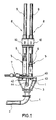
- the conveyor device shown in Fig. 1 shows in a Top view of an approximately funnel-shaped container 1 for receiving of concrete, for example from ready-mixed concrete mixers.
- the concrete is in an only indicated delivery line 2 via Swivel pipe 3 and a pipe bend 4 promoted. This happens by means of two delivery cylinders 5, the delivery pistons 6 alternately one suction and one pressure stroke To run.
- the swivel tube 3 is hydraulic via a Slider 7 each in its desired position with respect to The mouth of the two feed cylinders 5 can be pivoted. 1 is the mouth of the suction feed cylinder 6 to the container 1st open so that the cylinder fills from there (see the arrow shown in dashed lines).
- the delivery pistons 6 are by means of cylinder-piston units 8 moves, of which in Fig. 1 only the cylinder 9 schematically are indicated.
- Housing 10 At the junction between the Delivery cylinders 5 and the cylinder-piston units 8 are Housing 10 arranged.
- the pivot tube 3 in this Embodiment funnel-shaped, so that both Delivery cylinder 5 at the same time as the delivery line 2 are temporarily connectable.
- FIG. 2 shows a first embodiment of a simplified schematics of a hydraulic system for actuation the cylinder-piston units 8 and so coupled delivery piston 6.
- a delivery cylinder 5 and Delivery pistons 6 are fragmentary and schematized in Connection with one of the cylinder-piston units S indicated. It is also schematized by the Hydraulic system actuated slide 7 indicated.
- Each cylinder-piston unit 8 has a piston 11, the Sequence of movements on his piston rod 12 on the Transfer piston 6 transmits.
- the drive for the cylinder-piston units in the pressure stroke takes place essentially by means of a hydraulic pump 13.
- a Auxiliary pump 14 supplies the for certain movement sections Piston additional flow.
- the hydraulic pipeline network has the following sections:
- a line 15 leads from the hydraulic pump 13 to a branching point 16 and from there a line 17 to a two-way valve 18 and a line 19 to a changeover valve 20. From the two-way valve 18, a line 21 leads to the area of a cylinder 9 1 on the piston side.
- the index designations 1 and 2 are used below for the two piston-cylinder units when describing their movement sequences).
- a line 22 leads from the two-way valve 18 into the piston-side pressure chamber of the cylinder 9 2 .
- the strands 21 and 22 are thus selectively connectable to the hydraulic pump 13 through the two-way valve 18.
- a strand 23 leads from the changeover valve 20 to the one Strand 24 to the other side of a piston 7a in slide 7.
- a strand 25 leads from the switching valve 20 to the return 26 such that, depending on the valve position, one side of the slide 7 with the hydraulic pump 13 and the other with the Return 26 is connected.
- a wiring harness 27 connects the two piston end regions of the cylinders 9 1 and 9 2 to one another. Between the two branches 28 to a switch valve 29. Before the end of the branch 28 into the cylinders 9 1 and 9 2 , the branch 27 each contains a check valve 30 or 31, each with the closing direction towards the branch 28.
- a line 32 leads to the return 26 and a line 33 to the auxiliary pump 14.
- a line 34 leads from the changeover valve 29 into the area of the cylinder-piston units, where it flows into the areas of the cylinders 9 1 and 9 2 on the rod side connecting strand 35 opens. This line contains no valves.
- a control line 36 runs between the piston-side area of the cylinder 9 1 and the control connection side of the check valve 31. Likewise, the cylinder 9 2 is connected to the check valve 30 via a control line 37.
- the hydraulic pump 13 is a pressure relief valve 38 which Additional pump 14 assigned a pressure relief valve 39.
- Two-way valve 18 is a sequence of movements of the pistons 11 achievable, based on Figures 3 to 7 below is described.
- the sequence of movements applies in the same way for the delivery piston 6 and thus determines the delivery of concrete the container 1 into the delivery line 2.
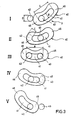
- the Delivery cylinder 5 facing end face 40 of the swivel tube 3 in is essentially kidney-shaped.
- the width B essentially the diameter D of the mouth opening 42, 43 of the Delivery cylinder 5 corresponds.
- the length L of the inlet opening 41 corresponds to the external distance A of the two orifices 42, 43.
- the inlet opening 41 thus has the shape of a curved one Elongated, whose arc center in the pivot axis 44 of the Swivel tube 3 is.
- each inlet opening 41 on the smallest distance C from the inlet opening 41 to Outer edge to the diameter D of the mouth openings 42, 43 corresponds.
- the end face 40 of the swivel tube 3 this runs funnel-shaped on its second with the Supply line 2 connected end to.
- the inlet opening 41 is also reduced to the funnel shape corresponding opening at the opposite end.
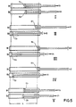
- the transition states can be essentially determined by the The swivel tube 3 is designed according to the invention in FIG. 3 shown, five states for the control of the system are critical to achieve.
- the starting position for phase I is the position of the pistons and the swivel tube, as shown in FIGS. 3 and 5.
- the hydraulic pump 13 acts on the cylinder 9 1 via the branch 15, the valve 18 and the branch 21 with a pressure P 1 .
- the hydraulic pump 13 holds the slide 7 in its position on the right in the figure via the strands 15, 19 and 23 and the valve 20.
- the right side of the slide is connected to the outlet 26 via the changeover valve 20.
- the rod-side areas of the cylinders 9 1 and 9 2 are connected to the return 26 via the strands 35, 34 and the changeover valve 29.
- the auxiliary pump 14 is connected via the strands 33, 34 and 35 and the valve 29 to the end of the pistons 11 1 , 11 2 on the piston rod side.
- the additional pump 14 now applies a pressure P 2 to the cylinders 91 and 9 2 in their region on the piston rod side.
- the pressure P 2 is less than the pressure P 1 .
- the piston 11 1 therefore presses the liquid to be displaced by it into the line 35 against the pressure P 2.
- the piston 11 1 thus receives an additional pressurization on the rod side for the action of the pump 14. Its return stroke takes place at the speed V 3 . This stroke movement corresponds to the suction stroke of the associated delivery piston 6.
- the piston 11 1 has not yet completed its pressure stroke when entering phase II, while the piston 11 2 is already finished with its suction stroke.
- the changeover time range t u begins with phase II.
- the piston 11 2 and thus the corresponding delivery piston 6 are at a standstill.
- the advantage lies particularly in the fact that the closure area 46 of the end face 40 is not subjected to unnecessary high pressure.
- the pivot tube 3 pivots in phase II by switching the valve 20 so far that the orifice 42 is separated from the container 1.
- both mouth openings 42, 43 and thus both delivery cylinders 5 are now short-circuited with the inlet opening 41 and thus the delivery line 2.
- the two-way valve 18 switches.
- the hydraulic pump 13 is connected to the area of the cylinder 9 2 on the piston side.
- the piston 11 2 now carries out a pressure stroke at the speed V 1 until the end of phase IV is reached.
- the swivel tube 3 pivots further in such a way that the outflow region 45 gradually sweeps over the mouth opening 43.
- the piston 11 1 is stationary during this time.
- the movement sequence of the swivel tube 3 shown in FIG. 3 thus takes place between the end of phase I and the beginning of phase V, that is to say during the changeover period of the t u .
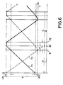
- the switching positions assigned to the travel-time diagram during the pivoting movement of the pivoting tube 3, see FIG. 3, can be configured variably and do not have to be carried out exactly according to this exemplary embodiment. Overlaps of the phases may even be desirable depending on the operating conditions. 4 clearly shows that the pressure strokes of the cylinders 11 1 and 11 2 detach at the same conveying speed V 1 without loss of time at the end of the time interval ⁇ t and thus provide a continuous flow.
- the device shown in Fig. 2 is in particular by the switching valve 29, the check valves 30, 31, and their Control lines 36, 37 capable of one of the cylinders 9 already to let its pressure stroke begin while the other cylinder 9 has not yet completed its pressure stroke. This is particularly so then advantageous if possible losses, for example through insufficient filling or air pockets in the concrete, must be balanced.
- the additional pump 14 is connected to the front end of the piston 9 2 via the strands 33, 28, 27 and the valves 29, 31.
- the auxiliary pump 14 thus acts on the piston 11 2 with a pressure P 2 from the beginning of phase II to the beginning of phase III during the period ⁇ t.
- the piston 11 1 ends the pressure stroke at the speed V 1 .
- the piston 11 2 already begins its pressure stroke under the action of the pressure P 2 at a speed V 2 which is less than the speed V 1 .
- the changeover valve 18 switches over and the additional pump 14 is separated from the front end of the piston P 2 .
- the speed of the delivery piston changes.
- the concrete is pressed out of the delivery cylinder into the delivery line 2 without the risk of a sudden transition, a stall or even a return caused by poor filling.
- the changeover process has ended, that is to say after the time t u has elapsed, the other delivery piston is moved in the direction of its suction stroke, more quickly than in the pressure stroke.
- the increase in speed is made possible by the additional pump 14. It ensures that the suction stroke is ended at the moment in which a new pressure stroke is initiated by appropriate switching operations before the other piston has completely completed its pressure stroke.
- the scheme shown in FIG. 8 has two essentially equivalent variable displacement pumps 13, 14 for control purposes.
- the first variable pump 13 is connected via line 15, a 4/2-way valve 45 and a line 21 to the piston-side pressure chamber of cylinder 9 1 .
- the directional control valve 45 ensures that the variable displacement pump 13 is connected via the line 15 and the line 46 to the space on the piston rod side of the cylinder 9 1 .
- the variable displacement pump 14 is connected via the line 33, a 4/2-way valve 47 and the line 22 to the pressure chamber of the cylinder 9 2 on the piston side.
- the variable displacement pump 14 is connected via the cable 48 with the piston rod side chamber of the cylinder 9 2 in connection.
- variable pumps 13, 14 are matched to one another. From the circuit it can be seen that each cylinder 9 1 , 9 2 can be controlled and operated separately via the associated variable displacement pump 13, 14. It follows that the actuation of the variable displacement pumps 13, 14 and the directional control valves 45, 47 is solely responsible for the extension and retraction of the cylinders 9 1 , 9 2 and their actuation must take place accordingly. Furthermore, an additional pump 49 with a subsequent pressure accumulator 50 is provided, which are connected to the slide 7 via the line 19 and the 4/2-way valve 20. The pressure accumulator 50 ensures that the pump 49 does not have to be in continuous operation. In this context, however, an embodiment is also conceivable in which the pressure accumulator 50 is filled by one of the variable displacement pumps 13, 14 during the downtime of one of the pistons 11 1 , 11 2 .
- the diagram shown in Fig. 9 comprises a variable displacement pump 13, which is connected via a line 15, a 4/3-way valve 51 and the branches 46, 48 to the piston rod-side spaces of the cylinders 9 1 , 9 2 .
- the directional control valve 51 has a position in which the strands 46, 48 are separated from the pump 13 and are connected to the pressure medium return 26 via the strand 25.
- a second variable displacement pump 14 is provided, which is optionally connected via the line 33, a 4/3-way valve 52 and the lines 53, 54 to the pressure chambers of the cylinders 9 1 and 9 2 on the piston side.
- the directional control valve 52 connects both pressure chambers of the cylinders 9 1 and 9 2 to the pump 14.
- the speed ratio between the pressure and suction stroke can be kept constant by precisely controlling the directional control valves 51, 52 and the pumps 13, 14. This is particularly the case in this embodiment when both cylinders 9 1 and 9 2 perform a pressure stroke for a short time (see valve position in FIG. 9) and both piston rod sides of cylinders 9 1 and 9 2 are connected to the tank during this time. At the same time, the slide 7 is then actuated. This means that when the short circuit on the swivel tube 3 is established, both delivery cylinders 5 are in the pressure stroke at essentially half the average speed V1. The gradual switching from one to the other cylinder 9 1 and 9 2 had no effect on the total flow rate by adjusting the speeds.
- FIG. 10 differs from the previous one in that an adjustable flow divider 55, 56 is arranged in each line 46, 48 after the 4/3-way valve 51, from which the lines 46, 48 to the piston rod side Broaching of cylinders 9 1 and 9 2 are continued and a second line 57, 58 is connected via a 4/2-way valve 59 to the piston-side pressure chambers of cylinders 9 1 and 9 2 .
- the pressure or suction stroke can be generated by the variable pump 13.
- the 4/3-way valve 51 connects the lines 46, 48 to the pressure medium return 26 and the 4/2-way valve 49 blocks the lines 57, 58, so that no oil volume from the piston-side pressure chambers of the cylinders 9 1 and 9 2 can escape.
- the variable displacement pump 14 is simultaneously connected to both pressure chambers of the cylinder 9 1 and 9 2 on the piston side. These then perform a pressure stroke at the same speed depending on the delivery volume of the variable displacement pump 14.
- one cylinder is usually shortly before its end position and the other at the beginning of its pressure stroke.
- the delivery volume of the variable displacement pump 14 is usually selected so that no delivery flow fluctuations occur.
- the parts ratio of the flow dividers 55, 56 and the area ratio of the piston end face and the piston rod side of the cylinders 9 1 and 9 2 must be designed in order to obtain a reasonable relationship between pressure stroke and suction stroke speed.
- the device is fine-tuned by the variable displacement pump 14, which can be set accordingly to generate higher or lower speeds.
- FIG. 11 a fifth embodiment of a hydraulic scheme for driving the delivery cylinders 5 is shown in FIG. 11.
- the line 15 from the variable displacement pump 13 is in turn connected via a 4/3-way valve 51 and the branches 46, 48 to the piston rod-side spaces of the cylinders 9 1 and 9 2 .
- a line 59 branches off from line 15 before directional valve 51 is reached.
- the line 59 connects the line 15 and thus the pump 13 to a rocker line 61 via a 3/2-way valve 60.
- the rocker line 61 is connected directly to both pressure chambers 9 1 and 9 2 on the piston side.
- a line 62 which is also connected to the 3/2-way valve 60, leads via a further 3/2-way valve to the pressure medium return 26.
Landscapes
- Engineering & Computer Science (AREA)
- Mechanical Engineering (AREA)
- General Engineering & Computer Science (AREA)
- Reciprocating Pumps (AREA)
Claims (14)
- Procédé pour transférer du béton ou d'autres matières épaisses d'un récipient (1) dans une conduite de livraison (2) au moyen de deux cylindres de transfert (5) qui peuvent être reliés alternativement au récipient (1) ou à la conduite de livraison (2) par un dispositif inverseur (3), et dont les pistons de transfert (6) décrivent ensemble alternativement une course d'aspiration et une course de pression, la vitesse moyenne V3 des pistons étant au moins temporairement plus grande pendant la course d'aspiration que pendant la course de pression, cependant que pendant le laps de temps tu de l'inversion du dispositif inverseur (3), les deux cylindres de transfert (5) sont, au moins temporairement, sensiblement séparés du réservoir (1) et court-circuités l'un avec l'autre en même temps qu'ils sont reliés en commun à la conduite de livraison (2) et, dans cet état, l'un des pistons de transfert (6) est encore en train de terminer sa course de pression et, simultanément, l'autre piston de transfert (6) commence déjà sa course de pression, le piston de transfert (6) correspondant ne décrivant sa course d'aspiration que lorsque le court-circuit est sensiblement de nouveau supprimé et que le cylindre de transfert (6) associé est relié au récipient (1), caractérisé en ce que le court-circuit est établi par un unique dispositif inverseur (3) qui isole simultanément les deux cylindres de transfert (5) du récipient (1) pendant la période de court-circuit.
- Procédé selon la revendication 1, caractérisé en ce que le piston de transfert (6) qui a terminé la course d'aspiration commence déjà la course de pression pendant un laps de temps Δt du laps de temps d'inversion tu alors que l'autre piston de transfert (6) n'a pas encore terminé sa course de pression.
- Procédé selon la revendication 2, caractérisé en ce que la vitesse V2 du piston de transfert (6) qui commence la course de pression dans le laps de temps Δt est plus petite que la vitesse moyenne V1 du reste de la course de pression.
- Procédé selon la revendication 2 ou 3, caractérisé en ce que, pendant le laps de temps Δt, les deux pistons de transfert (6) sont mis en mouvement à une vitesse sensiblement égale à la moitié de la vitesse moyenne V1 du reste de la course de pression.
- Dispositif pour la mise en oeuvre du procédé selon l'une des revendications 1 à 4, comprenant au moins deux cylindres de transfert (5) qui peuvent être reliés alternativement en communication à un réservoir (1) ou à une conduite de livraison (2) par un dispositif inverseur (3) et dont les pistons de transfert (6) décrivent ensemble alternativement une course d'aspiration et une course de pression, le dispositif inverseur (3) étant un tube oscillant (3) dont on peut faire osciller l'ouverture d'entrée (41) le long des régions d'extrémité ouvertes (42, 43) des cylindres de transfert (5), caractérisé en ce que l'ouverture d'entrée (41) et les régions de fermeture (40, 46) du tube oscillant (3) l'encadrant sont configurées de manière que, pendant une opération d'inversion, les cylindres de transfert (5) soient sensiblement court-circuités avec le tube de livraison (2) mais sensiblement isolés du récipient (1).
- Dispositif selon la revendication 5, caractérisé en ce que l'ouverture d'entrée (41) est réalisée sous la forme d'un trou allongé incurvé sensiblement autour de l'axe d'oscillation (44) du tube oscillant (3) et présente une longueur L qui correspond à peu près à l'écartement extérieur A des deux ouvertures de débouché (42, 43).
- Dispositif selon la revendication 5 ou 6, caractérisé en ce que les régions de fermeture (45, 46) sont disposées dans le prolongement du trou allongé (41) et présentent une largeur C qui correspond sensiblement au diamètre D des ouvertures de débouché (41, 43).
- Dispositif selon l'une des revendications 5 à 7, caractérisé en ce qu'il est prévu dans chaque cas une unité cylindre-piston (8) d'où part une conduite (17) sélectivement commutable qui mène dans la chambre côté piston de chaque cylindre (9), en ce qu'une pompe additionnelle (14) destinée à compléter l'alimentation en fluide de pression des deux chambres de pression des deux unités à cylindre-piston (8) est disposée, en ce qu'entre les chambres de pression côté face de piston des unités à cylindre-piston (8) s'étend une branche reliante (27) de l'installation hydraulique, dans laquelle débouche une branche (28) qui peut être sélectivement reliée par un dispositif inverseur (29) à la pompe additionnelle (14) ou à un retour de fluide de pression (26), en ce que les segments de la branche (27) entre chaque cylindre (9) et le débouché de la branche (28) comprennent à chaque fois un clapet anti-retour (30, 31) qui peut être fermé par la pression régnant dans le cylindre (9) et en ce que les cylindres (9) des unités cylindre-piston (8) présentent, dans les régions terminales de leurs côtés tige de piston une branche (35) les reliant et qui peut être reliée sélectivement, également au moyen du dispositif inverseur (29), au retour de fluide de pression (26) ou à la pompe additionnelle (14).
- Dispositif selon la revendication 8, caractérisé en ce qu'à son extrémité côté face de piston, chaque cylindre (9) est relié, par une conduite de commande (36, 37) à l'extrémité de raccordement de commande du clapet anti-retour (31, 30) associé à l'autre cylindre (9).
- Dispositif selon l'une des revendications 5 à 7, caractérisé en ce qu'il est prévu à chaque fois une unité à cylindre-piston (8) pour entraíner les pistons de transfert (6), les unités pouvant être alimentées en fluide de pression chacune au moyen d'une pompe séparée (13, 14).
- Dispositif selon l'une des revendications 5 à 7, caractérisé en ce qu'il est prévu à chaque fois une unité cylindre-piston (8) pour entraíner les pistons de transfert (6), pour laquelle une conduite (15) sélectivement commutable d'une première pompe (13) peut être reliée à la chambre côté tige de piston de chaque cylindre (9) ou en être séparée, en ce qu'une deuxième pompe (14) pour l'alimentation en fluide de pression des chambres de pression côté face de piston des cylindres (9) peut être reliée par une conduite commutable (33), individuellement ou conjointement, aux chambres de pression et en ce que les chambres côté tige de piston des cylindres (9) peuvent être reliées conjointement à un retour de fluide de pression (26).
- Dispositif selon l'une des revendications 5 à 7, caractérisé en ce qu'il est prévu à chaque fois une unité cylindre-piston (8) pour entraíner les pistons de transfert (6), pour laquelle une conduite sélectivement commutable (15) d'une première pompe (13) peut être reliée, par un diviseur de débit réglable (55, 56) simultanément à la chambre de pression côté face de piston d'un des deux cylindres (9) et à la chambre côté tige de piston de l'autre cylindre (9) ou en être séparée, en ce qu'une deuxième pompe (14) pour l'alimentation en fluide de pression des chambres de pression côté face de piston peut être reliée, au moyen d'une conduite commutable (33), individuellement ou conjointement aux chambres de pression, en ce que les diviseurs de débit (55, 56) peuvent être ouverts conjointement sur les branches (57, 58) pouvant être reliées aux chambres de pression côté face de piston des cylindres (9) ou fermés conjointement et en ce que les diviseurs de débit (55, 56) lorsqu'ils sont séparés de la première pompe (13), peuvent être reliés conjointement à un retour de fluide de pression (26).
- Dispositif selon l'une des revendications 5 à 7, caractérisé en ce qu'il est prévu à chaque fois une unité cylindre-piston (8) pour entraíner les pistons de transfert (6), pour laquelle une conduite sélectivement commutable (15) d'une pompe (13) peut être reliée à la chambre côté tige de piston de chaque cylindre (9) ou en être séparée, en ce qu'une deuxième conduite sélectivement commutable (59) de cette pompe (13) peut être reliée conjointement aux chambres de pression côté face de piston des cylindres ou en être séparée, en ce que les chambres de pression côté face de piston des cylindres (9) sont reliées entre elles au moyen d'une conduite à bascule (61) et en ce que les chambres de pression côté face de piston peuvent être reliées à un retour de fluide de pression (26) au moyen d'une conduite sélectivement commutable (63) ou en être séparées.
- Dispositif selon l'une des revendications 5 à 13, caractérisé en ce que le tube oscillant (3) peut être actionné au moyen d'un poussoir (7) par l'intermédiaire d'un distributeur à deux voies commandées (20) qui est relié à une pompe et/ou à un accumulateur de pression.
Applications Claiming Priority (3)
| Application Number | Priority Date | Filing Date | Title |
|---|---|---|---|
| DE19503986A DE19503986A1 (de) | 1995-02-07 | 1995-02-07 | Verfahren und Vorrichtung zum Fördern von Beton oder anderen Dickstoffen |
| DE19503986 | 1995-02-07 | ||
| PCT/EP1996/000228 WO1996024767A1 (fr) | 1995-02-07 | 1996-01-19 | Procede et dispositif de transfert de beton ou d'autres liquides epais |
Publications (2)
| Publication Number | Publication Date |
|---|---|
| EP0808422A1 EP0808422A1 (fr) | 1997-11-26 |
| EP0808422B1 true EP0808422B1 (fr) | 1998-11-11 |
Family
ID=7753363
Family Applications (1)
| Application Number | Title | Priority Date | Filing Date |
|---|---|---|---|
| EP96901313A Expired - Lifetime EP0808422B1 (fr) | 1995-02-07 | 1996-01-19 | Procede et dispositif de transfert de beton ou d'autres liquides epais |
Country Status (7)
| Country | Link |
|---|---|
| US (1) | US5993181A (fr) |
| EP (1) | EP0808422B1 (fr) |
| JP (1) | JP3081923B2 (fr) |
| KR (1) | KR100264234B1 (fr) |
| CN (1) | CN1177393A (fr) |
| DE (1) | DE19503986A1 (fr) |
| WO (1) | WO1996024767A1 (fr) |
Cited By (3)
| Publication number | Priority date | Publication date | Assignee | Title |
|---|---|---|---|---|
| DE102018132270A1 (de) | 2018-12-14 | 2020-06-18 | Schwing Gmbh | Kolbenpumpe und Verfahren zum Betrieb einer Kolbenpumpe |
| WO2020120234A1 (fr) | 2018-12-14 | 2020-06-18 | Schwing Gmbh | Pompe à piston et procédé pour faire fonctionner une pompe à piston |
| DE102018132309A1 (de) | 2018-12-14 | 2020-06-18 | Schwing Gmbh | Kolbenpumpe und Verfahren zum Betrieb einer Kolbenpumpe |
Families Citing this family (33)
| Publication number | Priority date | Publication date | Assignee | Title |
|---|---|---|---|---|
| IT1294068B1 (it) * | 1997-01-17 | 1999-03-22 | Gianguido Ravellini | Dispositivo di pompaggio, in particolare per materiale cementizio. |
| DE19959217A1 (de) * | 1999-12-08 | 2001-06-13 | Putzmeister Ag | Verfahren und Anordnung zum Betonieren von vertikalen Schächten |
| US6637625B1 (en) * | 2000-04-19 | 2003-10-28 | Delaware Capital Formation | Continuous positive displacement metering valve |
| DE10343802B4 (de) * | 2003-09-22 | 2007-12-06 | Schwing Gmbh | Kolben-Dickstoffpumpe mit kontinuierlichem Förderstrom |
| DE102004025910B4 (de) * | 2004-05-27 | 2009-05-20 | Schwing Gmbh | Antriebseinrichtung für eine Zweizylinderdickstoffpumpe und Verfahren zum Betrieb derselben |
| DE102005032915B3 (de) * | 2005-07-12 | 2007-02-22 | Schwing Gmbh | Betonfördervorrichtung mit einem Hydrauliksystem |
| EP3501734B1 (fr) * | 2008-03-26 | 2024-06-12 | Quantum Servo Pumping Technologies Pty Ltd | Pompe ultra-haute pression à mécanisme d'entraînement à déplacement de rotation/linéaire alternatif |
| DE102009005318B3 (de) | 2009-01-16 | 2010-09-30 | Schwing, Friedrich, Dipl.-Ing. | Verfahren zur Förderung breiiger Massen und Pumpvorrichtung zur Förderung breiiger Massen |
| US8231362B2 (en) * | 2009-02-10 | 2012-07-31 | Innoventor Renewable Power, Inc. | Multi-chambered pump |
| KR101028831B1 (ko) | 2009-04-27 | 2011-04-12 | 주식회사 리더스큐엠 | 콘크리트 압송용 혼화제 투입장치 |
| WO2012034165A1 (fr) | 2010-09-13 | 2012-03-22 | Techni Waterjet Pty Ltd | Pompe à ultra haute pression |
| NL2005671C2 (nl) * | 2010-11-11 | 2012-05-14 | Poppe Beheer B V C | Werkwijze en inrichting voor het verpompen van visceuze massa, in het bijzonder mortel. |
| CN102700941B (zh) * | 2012-05-31 | 2014-04-02 | 东南大学 | 密闭空腔型变压干粉泵装置 |
| CN102700940B (zh) * | 2012-05-31 | 2014-05-07 | 东南大学 | 一种压缩型变压粉体泵装置 |
| DE102013104494B4 (de) * | 2013-05-02 | 2023-11-30 | MPS-Matter Pumpsysteme GmbH | Dickstoffpumpe |
| KR101340285B1 (ko) * | 2013-05-07 | 2013-12-10 | 권순형 | 콘크리트 펌프카용 밸브 구동장치 및 그의 제어방법 |
| DE102013215990A1 (de) * | 2013-08-13 | 2015-02-19 | Putzmeister Engineering Gmbh | Zweizylinder-Dickstoffpumpe mit Rohrweiche |
| CN103603746B (zh) * | 2013-11-22 | 2016-01-20 | 南京理工大学 | 凝胶膏体火箭发动机推进剂的持续供给装置 |
| US9765768B2 (en) * | 2014-01-15 | 2017-09-19 | Francis Wayne Priddy | Concrete pump system and method |
| AR103757A1 (es) * | 2015-02-23 | 2017-05-31 | Schlumberger Technology Bv | Métodos y sistemas para presurizar fluidos agresivos |
| EP3282125A1 (fr) | 2016-08-11 | 2018-02-14 | Putzmeister Engineering GmbH | Vanne pour matériaux visqueux |
| DE102016122392A1 (de) | 2016-11-21 | 2018-05-24 | Schwing Gmbh | Dickstoffpumpe mit einstellbarer Begrenzung des Förderdrucks |
| US10001114B1 (en) * | 2017-03-28 | 2018-06-19 | Jessop Initiatives LLC | Continuous flow pumping system |
| NL2019357B1 (en) * | 2017-07-27 | 2019-02-18 | Weir Minerals Netherlands Bv | Pump system for handling a slurry medium |
| CN109098959B (zh) * | 2018-07-24 | 2019-12-03 | 山东科技大学 | 一种混凝土湿喷机分配阀结构 |
| CN109989900B (zh) * | 2019-05-24 | 2024-06-07 | 徐州徐工施维英机械有限公司 | 糊状物料输送装置及其控制方法和工程车辆 |
| CN110552508B (zh) * | 2019-09-11 | 2021-05-04 | 上海市市政规划设计研究院有限公司 | 超高性能混凝土钢纤维定向排列的方法 |
| JP7084056B1 (ja) * | 2020-12-28 | 2022-06-14 | 株式会社シンテック | 流動化処理土の圧送方法及びその装置並びに解泥水の圧送方法及びその装置 |
| KR102464912B1 (ko) * | 2020-12-30 | 2022-11-10 | 우리기술 주식회사 | 콘크리트 균열보수용 무기계 조성물 및 이를 이용한 콘크리트 균열보수방법 |
| DE102021100981B3 (de) * | 2021-01-19 | 2022-04-28 | Putzmeister Engineering Gmbh | Dickstoffventil und Verfahren zum Betätigen eines Dickstoffventils |
| CN113338623A (zh) * | 2021-06-01 | 2021-09-03 | 浙江鸿翔建设集团股份有限公司 | 一种混凝土泵送的压力补偿装置 |
| DE102021212756B3 (de) * | 2021-11-12 | 2022-11-10 | Putzmeister Engineering Gmbh | Hydraulikantriebssystem für ein Bau- und/oder Dickstoffpumpensystem, Bau- und/oder Dickstoffpumpensystem und Verfahren zum Betreiben eines Hydraulikantriebssystems und/oder eines Bau- und/oder Dickstoffpumpensystems |
| DE202022107228U1 (de) * | 2022-12-23 | 2024-03-27 | Puwe Gmbh | Doppelkolbenpumpe mit axial verschiebbarem Steuerkolben |
Family Cites Families (7)
| Publication number | Priority date | Publication date | Assignee | Title |
|---|---|---|---|---|
| GB1291846A (en) * | 1968-12-31 | 1972-10-04 | Georg Stetter | Concrete pump |
| US3663129A (en) * | 1970-09-18 | 1972-05-16 | Leon A Antosh | Concrete pump |
| US4191309A (en) * | 1977-11-23 | 1980-03-04 | Marlen Research Corporation | Product portioning in the continuous pumping of plastic materials |
| US4533300A (en) * | 1979-06-11 | 1985-08-06 | Robert E. Westerlund | High pressure pumping apparatus for semi-fluid material |
| US4343598A (en) * | 1980-03-14 | 1982-08-10 | Friedrich Wilh. Schwing Gmbh | Viscous material pump, particularly for concrete |
| DE3525003A1 (de) * | 1985-07-01 | 1987-01-08 | Gerhard Dr Hudelmaier | Verfahren und vorrichtung zum foerdern von beton aus einem behaelter in eine lieferleitung |
| DE4215403C2 (de) * | 1991-05-16 | 2000-10-19 | Mbt Holding Ag Zuerich | Doppelkolbenpumpe zum Fördern von flüssigen Materialien, insbesondere von Beton oder Mörtel |
-
1995
- 1995-02-07 DE DE19503986A patent/DE19503986A1/de not_active Ceased
-
1996
- 1996-01-19 JP JP08523925A patent/JP3081923B2/ja not_active Expired - Fee Related
- 1996-01-19 CN CN96192285A patent/CN1177393A/zh active Pending
- 1996-01-19 WO PCT/EP1996/000228 patent/WO1996024767A1/fr not_active Ceased
- 1996-01-19 US US08/930,687 patent/US5993181A/en not_active Expired - Lifetime
- 1996-01-19 EP EP96901313A patent/EP0808422B1/fr not_active Expired - Lifetime
- 1996-01-19 KR KR1019970705452A patent/KR100264234B1/ko not_active Expired - Fee Related
Cited By (4)
| Publication number | Priority date | Publication date | Assignee | Title |
|---|---|---|---|---|
| DE102018132270A1 (de) | 2018-12-14 | 2020-06-18 | Schwing Gmbh | Kolbenpumpe und Verfahren zum Betrieb einer Kolbenpumpe |
| WO2020120234A1 (fr) | 2018-12-14 | 2020-06-18 | Schwing Gmbh | Pompe à piston et procédé pour faire fonctionner une pompe à piston |
| DE102018132309A1 (de) | 2018-12-14 | 2020-06-18 | Schwing Gmbh | Kolbenpumpe und Verfahren zum Betrieb einer Kolbenpumpe |
| US11891987B2 (en) | 2018-12-14 | 2024-02-06 | Schwing Gmbh | Piston pump and method for operating a piston pump |
Also Published As
| Publication number | Publication date |
|---|---|
| US5993181A (en) | 1999-11-30 |
| JP3081923B2 (ja) | 2000-08-28 |
| WO1996024767A1 (fr) | 1996-08-15 |
| CN1177393A (zh) | 1998-03-25 |
| KR100264234B1 (ko) | 2000-09-01 |
| DE19503986A1 (de) | 1996-08-08 |
| KR19980702057A (ko) | 1998-07-15 |
| EP0808422A1 (fr) | 1997-11-26 |
| JPH10505647A (ja) | 1998-06-02 |
Similar Documents
| Publication | Publication Date | Title |
|---|---|---|
| EP0808422B1 (fr) | Procede et dispositif de transfert de beton ou d'autres liquides epais | |
| EP0465474B1 (fr) | Agencement de commande de pompes a liquides epais a deux cylindres | |
| DE1812208A1 (de) | Vorrichtung zur Synchronisierung von Hydraulikzylinderantrieben | |
| DE3048776A1 (de) | Druckwandlergeraet | |
| DE4210504A1 (de) | Antrieb zur Hubverlagerung für Umformmaschinen | |
| DE102004009362B4 (de) | Kolben-Dickstoffpumpe | |
| WO1989011037A1 (fr) | Agencement de commande de pompes a double cylindre pour liquides epais | |
| DE3525003C2 (fr) | ||
| DE1503334A1 (de) | Hydraulische Vorrichtung zum Erzeugen einer hin- und hergehenden Bewegung | |
| WO1986001260A1 (fr) | Pompe duplex a piston | |
| EP1526930B1 (fr) | Cylindre principal ou cylindre de compression d'une extrudeuse | |
| EP4281668B1 (fr) | Vanne pour produits épais et procédé d'actionnement d'une vanne pour produits épais | |
| EP0280901B1 (fr) | Pompe à piston plongeur | |
| DE69212549T2 (de) | Verfahren zum Ausblasen der zwischen Matrize und Knüppel eingesperrten Luft in einer Strangpresse | |
| DE102011054616B3 (de) | Hydraulisch angetriebene Anordnung zum linearen Bewegen eines Massekörpers | |
| DE4311275C2 (de) | Folgesteuerung oder Vorrangschaltung für einen Drehpflug mit Pflugrahmeneinschwenkung | |
| DE3627375C2 (fr) | ||
| DE6803021U (de) | Vorrichtung felgesteuerung fuer einen hydraulischen motor | |
| DE2857176C1 (de) | Hydraulischer Antrieb fuer den Schuetzen einer Webmaschine | |
| DE2456878A1 (de) | Druckmittelbetaetigter stellzylinder | |
| DE102021107375B4 (de) | Vorrichtung zum Antreiben einer Messerschiene eines Mähwerks, Mähkorb und Verfahren zum Betreiben eines Mähwerks | |
| DE3346820A1 (de) | Hydrostatischer antrieb fuer eine betonkolbenpumpe | |
| CH404326A (de) | Antriebsvorrichtung mit gradlinigen, nach Länge und Geschwindigkeit veränderbaren Hubbewegungen | |
| DE3145401A1 (de) | Druckuebersetzte kraftzylindereinheit | |
| DE2249683C2 (de) | Steuervorrichtung für einen Druckflüssigkeits-Schubkolbenmotor |
Legal Events
| Date | Code | Title | Description |
|---|---|---|---|
| PUAI | Public reference made under article 153(3) epc to a published international application that has entered the european phase |
Free format text: ORIGINAL CODE: 0009012 |
|
| 17P | Request for examination filed |
Effective date: 19970807 |
|
| AK | Designated contracting states |
Kind code of ref document: A1 Designated state(s): IT |
|
| GRAG | Despatch of communication of intention to grant |
Free format text: ORIGINAL CODE: EPIDOS AGRA |
|
| 17Q | First examination report despatched |
Effective date: 19971223 |
|
| GRAG | Despatch of communication of intention to grant |
Free format text: ORIGINAL CODE: EPIDOS AGRA |
|
| GRAH | Despatch of communication of intention to grant a patent |
Free format text: ORIGINAL CODE: EPIDOS IGRA |
|
| GRAH | Despatch of communication of intention to grant a patent |
Free format text: ORIGINAL CODE: EPIDOS IGRA |
|
| GRAA | (expected) grant |
Free format text: ORIGINAL CODE: 0009210 |
|
| AK | Designated contracting states |
Kind code of ref document: B1 Designated state(s): IT |
|
| ITF | It: translation for a ep patent filed | ||
| PLBE | No opposition filed within time limit |
Free format text: ORIGINAL CODE: 0009261 |
|
| STAA | Information on the status of an ep patent application or granted ep patent |
Free format text: STATUS: NO OPPOSITION FILED WITHIN TIME LIMIT |
|
| 26N | No opposition filed | ||
| PGFP | Annual fee paid to national office [announced via postgrant information from national office to epo] |
Ref country code: IT Payment date: 20090626 Year of fee payment: 14 |
|
| PG25 | Lapsed in a contracting state [announced via postgrant information from national office to epo] |
Ref country code: IT Free format text: LAPSE BECAUSE OF NON-PAYMENT OF DUE FEES Effective date: 20100119 |