EP0808441B1 - Luftheizung und belüftungssystem mit wärmerückgewinnung mit sonnenkollektoren - Google Patents
Luftheizung und belüftungssystem mit wärmerückgewinnung mit sonnenkollektoren Download PDFInfo
- Publication number
- EP0808441B1 EP0808441B1 EP96902419A EP96902419A EP0808441B1 EP 0808441 B1 EP0808441 B1 EP 0808441B1 EP 96902419 A EP96902419 A EP 96902419A EP 96902419 A EP96902419 A EP 96902419A EP 0808441 B1 EP0808441 B1 EP 0808441B1
- Authority
- EP
- European Patent Office
- Prior art keywords
- air
- chamber
- house
- solar
- heat recovery
- Prior art date
- Legal status (The legal status is an assumption and is not a legal conclusion. Google has not performed a legal analysis and makes no representation as to the accuracy of the status listed.)
- Expired - Lifetime
Links
- 238000009423 ventilation Methods 0.000 title claims abstract description 34
- 238000011084 recovery Methods 0.000 title claims abstract description 33
- 238000010438 heat treatment Methods 0.000 title claims abstract description 27
- 239000006096 absorbing agent Substances 0.000 claims abstract description 10
- 230000005855 radiation Effects 0.000 claims abstract description 8
- 239000011248 coating agent Substances 0.000 claims abstract description 7
- 238000000576 coating method Methods 0.000 claims abstract description 7
- 239000006100 radiation absorber Substances 0.000 claims abstract description 7
- 239000012530 fluid Substances 0.000 claims abstract 4
- XLYOFNOQVPJJNP-UHFFFAOYSA-N water Substances O XLYOFNOQVPJJNP-UHFFFAOYSA-N 0.000 claims description 45
- 238000004891 communication Methods 0.000 claims description 6
- 230000000903 blocking effect Effects 0.000 claims description 4
- 239000005341 toughened glass Substances 0.000 claims description 2
- 239000011521 glass Substances 0.000 abstract 1
- XAGFODPZIPBFFR-UHFFFAOYSA-N aluminium Chemical compound [Al] XAGFODPZIPBFFR-UHFFFAOYSA-N 0.000 description 2
- 229910052782 aluminium Inorganic materials 0.000 description 2
- 239000004411 aluminium Substances 0.000 description 2
- 239000011888 foil Substances 0.000 description 2
- 239000004810 polytetrafluoroethylene Substances 0.000 description 2
- 229920001343 polytetrafluoroethylene Polymers 0.000 description 2
- 238000010792 warming Methods 0.000 description 2
- KXGFMDJXCMQABM-UHFFFAOYSA-N 2-methoxy-6-methylphenol Chemical compound [CH]OC1=CC=CC([CH])=C1O KXGFMDJXCMQABM-UHFFFAOYSA-N 0.000 description 1
- 239000004640 Melamine resin Substances 0.000 description 1
- 229920000877 Melamine resin Polymers 0.000 description 1
- 230000000740 bleeding effect Effects 0.000 description 1
- 238000010276 construction Methods 0.000 description 1
- 230000000694 effects Effects 0.000 description 1
- 238000001125 extrusion Methods 0.000 description 1
- 239000011152 fibreglass Substances 0.000 description 1
- 239000003365 glass fiber Substances 0.000 description 1
- 239000008236 heating water Substances 0.000 description 1
- 230000014759 maintenance of location Effects 0.000 description 1
- 239000000463 material Substances 0.000 description 1
- 239000011159 matrix material Substances 0.000 description 1
- 239000012466 permeate Substances 0.000 description 1
- 229920001568 phenolic resin Polymers 0.000 description 1
- 229920001296 polysiloxane Polymers 0.000 description 1
Images




Classifications
-
- F—MECHANICAL ENGINEERING; LIGHTING; HEATING; WEAPONS; BLASTING
- F24—HEATING; RANGES; VENTILATING
- F24D—DOMESTIC- OR SPACE-HEATING SYSTEMS, e.g. CENTRAL HEATING SYSTEMS; DOMESTIC HOT-WATER SUPPLY SYSTEMS; ELEMENTS OR COMPONENTS THEREFOR
- F24D5/00—Hot-air central heating systems; Exhaust gas central heating systems
- F24D5/005—Hot-air central heating systems; Exhaust gas central heating systems combined with solar energy
-
- F—MECHANICAL ENGINEERING; LIGHTING; HEATING; WEAPONS; BLASTING
- F24—HEATING; RANGES; VENTILATING
- F24D—DOMESTIC- OR SPACE-HEATING SYSTEMS, e.g. CENTRAL HEATING SYSTEMS; DOMESTIC HOT-WATER SUPPLY SYSTEMS; ELEMENTS OR COMPONENTS THEREFOR
- F24D19/00—Details
- F24D19/10—Arrangement or mounting of control or safety devices
- F24D19/1084—Arrangement or mounting of control or safety devices for air heating systems
- F24D19/109—Arrangement or mounting of control or safety devices for air heating systems system using solar energy
-
- F—MECHANICAL ENGINEERING; LIGHTING; HEATING; WEAPONS; BLASTING
- F24—HEATING; RANGES; VENTILATING
- F24S—SOLAR HEAT COLLECTORS; SOLAR HEAT SYSTEMS
- F24S80/00—Details, accessories or component parts of solar heat collectors not provided for in groups F24S10/00-F24S70/00
- F24S80/50—Elements for transmitting incoming solar rays and preventing outgoing heat radiation; Transparent coverings
-
- Y—GENERAL TAGGING OF NEW TECHNOLOGICAL DEVELOPMENTS; GENERAL TAGGING OF CROSS-SECTIONAL TECHNOLOGIES SPANNING OVER SEVERAL SECTIONS OF THE IPC; TECHNICAL SUBJECTS COVERED BY FORMER USPC CROSS-REFERENCE ART COLLECTIONS [XRACs] AND DIGESTS
- Y02—TECHNOLOGIES OR APPLICATIONS FOR MITIGATION OR ADAPTATION AGAINST CLIMATE CHANGE
- Y02B—CLIMATE CHANGE MITIGATION TECHNOLOGIES RELATED TO BUILDINGS, e.g. HOUSING, HOUSE APPLIANCES OR RELATED END-USER APPLICATIONS
- Y02B10/00—Integration of renewable energy sources in buildings
- Y02B10/20—Solar thermal
-
- Y—GENERAL TAGGING OF NEW TECHNOLOGICAL DEVELOPMENTS; GENERAL TAGGING OF CROSS-SECTIONAL TECHNOLOGIES SPANNING OVER SEVERAL SECTIONS OF THE IPC; TECHNICAL SUBJECTS COVERED BY FORMER USPC CROSS-REFERENCE ART COLLECTIONS [XRACs] AND DIGESTS
- Y02—TECHNOLOGIES OR APPLICATIONS FOR MITIGATION OR ADAPTATION AGAINST CLIMATE CHANGE
- Y02B—CLIMATE CHANGE MITIGATION TECHNOLOGIES RELATED TO BUILDINGS, e.g. HOUSING, HOUSE APPLIANCES OR RELATED END-USER APPLICATIONS
- Y02B10/00—Integration of renewable energy sources in buildings
- Y02B10/70—Hybrid systems, e.g. uninterruptible or back-up power supplies integrating renewable energies
-
- Y—GENERAL TAGGING OF NEW TECHNOLOGICAL DEVELOPMENTS; GENERAL TAGGING OF CROSS-SECTIONAL TECHNOLOGIES SPANNING OVER SEVERAL SECTIONS OF THE IPC; TECHNICAL SUBJECTS COVERED BY FORMER USPC CROSS-REFERENCE ART COLLECTIONS [XRACs] AND DIGESTS
- Y02—TECHNOLOGIES OR APPLICATIONS FOR MITIGATION OR ADAPTATION AGAINST CLIMATE CHANGE
- Y02E—REDUCTION OF GREENHOUSE GAS [GHG] EMISSIONS, RELATED TO ENERGY GENERATION, TRANSMISSION OR DISTRIBUTION
- Y02E10/00—Energy generation through renewable energy sources
- Y02E10/40—Solar thermal energy, e.g. solar towers
Definitions
- the present invention relates to an air heating and heat recovery ventilation system with one or more solar panels and more particularly with solar panels of the type which comprise a housing, a cover on the housing which transmits incident solar radiation into the housing, a solar radiation absorber in the housing, and air inlet and outlet ports to enable air to be circulated through the panel to collect heat from the panel.
- Document FR-A-2476806 discloses the features of an air ventilation system as found in the precharacterising portion of claim 1.
- Known solar panels are of the type described in EP-A-0 384 787.
- An object of the present invention is to provide a more efficient air heating and heat recovery ventilation system for use with solar panels.
- the present invention accordingly provides an air heating and heat recovery ventilation system comprising one or more solar panels for absorbing and collecting energy from the sun during daylight hours; an energy processing unit for combining and distributing energy from different sources; a boiler which is interlinked to the system via the energy processing unit; a control means which provides a means for co-ordinating and controlling all the components and functions of the system; and an air distribution system which allows for heat to be distributed throughout a house via a network of conduits.
- the energy processing unit includes an air handling unit which comprises an air-to-water heat exchanger and means for forcing the heated air from the solar panels through the heat exchanger, thereby transferring heat to water in the domestic hot water supply system; and forcing warm air emerging from the heat exchanger to flow around the house, characterised in that the energy processing unit comprises a four chamber housing, each chamber having a port, the first chamber being the fresh air intake chamber and having means to control and stop the intake of fresh air, a second chamber being the chamber which directs air to the solar panel and having a fan to force air through the system; a third chamber being the chamber which receives air returning from the solar panel and having means to control and stop the flow of air from the solar panel; and a fourth chamber being the chamber which directs heated air to the house and having the air-to-water heat exchanger, and the control means in the first chamber comprises a first damper movable between an open and closed position, the first damper in the closed position blocking the air intake into the unit and allowing communication between the first and fourth chambers, and in which
- the solar panel 1 fits within a rectangular space frame constructed from timber members 1a, 1b.
- a sheet of plasterboard with a foil backing is provided beneath the timber frame.
- a layer of long strand fibreglass 3 is provided beneath the timber frame.
- a solar radiation absorber 6 comprising a matrix of glass fibre which is bonded by a phenol formaldehyde resin or melamine resin.
- a housing cover 7 is fitted to the top of the unit and comprises a sheet of toughened glass, with a coating applied on its underside. The coating has a low emittance (“low E”) value.
- the solar panel also has a cover retention means comprising aluminium extrusions and silicone gaskets (not shown) and a series of air inlet ports (not shown) across one end of the panel, and a series of air outlet ports (not shown) across the other end of the panel to allow for circulation of air through the solar panel.
- a cover retention means comprising aluminium extrusions and silicone gaskets (not shown) and a series of air inlet ports (not shown) across one end of the panel, and a series of air outlet ports (not shown) across the other end of the panel to allow for circulation of air through the solar panel.
- the solar panel 1' includes the features of the solar panel 1 in addition to a layer of PTFE 10 over the absorber 6, an air gap 11 preferably in the range 15-40 mm, between the PTFE layer 10 and the housing cover 7, thus in effect creating a "double glazed" solar panel.
- the solar panel 1, 1' may be operated in an alternative mode in which air at a temperature lower than the ambient outdoor air temperature is circulated through the solar panel 1, where it is heated by thermal conduction through the housing cover 7, and the heat thus collected may be transferred to a heat store.
- the advantage of including the air gap 11 is that it results in the provision of a "double glazed" solar panel 1' which has an extremely low coefficient of thermal conductivity value.
- the typical value for the prior art solar panels is 11 whereas the typical value of the double glazed solar panel 1' is 4.5. This indicates that the solar panel 1' is much more effective than the prior art type of panel. The solar panel 1 has a level of effectiveness between these two values.
- the system includes solar panels 1 or 1' for absorbing and collecting energy from the sun during daylight hours and an energy processing unit indicated generally by reference numeral 50.
- the energy processing unit 50 comprising an air handling unit 105 and a heat recovery ventilation unit 110 is usually located in the attic of a house and combines and distributes energy from various different sources.
- the system also includes a boiler 100 which is interlinked to the system via the energy processing unit 50.
- a control means (not shown) provides a means for co-ordinating and controlling all the components and functions of the system.
- An air handling unit, indicated generally by reference numeral 105 is also provided which allows for heat to be distributed throughout the house via a network of conduits.
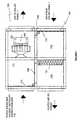
- the air handling unit 105 comprises a four chamber housing 106, the first chamber 111 being the fresh air intake chamber and has a damper 171 to control and stop the intake of fresh air, a second chamber 112 being the chamber which directs air to the solar panel 1 and housing the fan 153 to force air through the system; a third chamber 113 being the chamber which receives air returning from the solar panel 1 and has a damper 170 to control and stop the flow of air from the solar panel 1; and a fourth chamber 114 being the chamber which directs heated air to the house and having the air-to-water heat exchanger 151.
- the damper 171 is movable between an open and closed position. In the closed position it blocks the air intake into the unit and allows communication between the first and fourth chambers 111 and 114 through orifice 130.
- the damper 170 is movable between an open and closed position. In the closed position, it blocks the air flow from the solar panel 1 and allows communication between the second and third chambers 112 and 113 through orifice 135.
- the heating system includes a high output radiator or booster 180 which can be used when a high heat output is required in a short time.
- the air heating and heat recovery ventilation system can be operated in several different modes, namely, “solar” mode in which the system can rely on solar energy and can be used to deliver hot water with or without heating the house; “semi-solar” in which the system can be operated in the solar mode when there is sufficient solar energy for it to do so and in which heat can be added to from the boiler; and “boiler” mode in which the system relies entirely on the boiler to supply the required heat to the house as well as hot water in the domestic hot water supply.
- the warm air exiting from the heat exchanger 151 is forced throughout the house under action of fan 153 in the air handling unit 105, provided the house requires heat.
- the warm air is fed through the ducting system into all of the rooms via air diffusers 57a, 57b in the ceilings. Air is also removed from the house and is forced to flow over the heat recovery ventilation unit 110 (see Figure 6) under action of fan 160 in order to transfer its heat to the fresh air being brought into the house via conduit 155 (air-to-air heat exchange).
- This fresh air is forced by fan 153 in the heat recovery ventilation unit 110 to the solar panels 1 to start the cycle again.
- the system of the invention can also be operated in semi-solar mode. This will be described with reference to Figure 4.
- the air heating and heat recovery ventilation system of the invention can be operated so as to take advantage of whatever solar energy is available.
- the system will operate in "solar" mode as described above with reference to Figure 3 while there is sufficient solar energy available for it to do so.
- the system will operate in a semi-solar mode as will be described below.
- the house In the semi-solar mode, the house is heated partially by way of solar energy and this can be supplemented by an oil or gas fired boiler 100.
- This semi-solar mode would only be operational if the boiler 100 is switched on during the day-time. If the boiler 100 is not switched on, the system will attempt to keep the temperature in the house as close as possible to the pre-set temperature which has been programmed into the control panel.
- the air is circulated in the same route as in the solar mode described above except that in the semi-solar mode, heat is added to the air by way of hot water from the boiler 100 which is pumped to the air to water heat exchanger 151.
- the solar collectors 1 are only raising the temperature of the air from 20°C to 30°C. It is the boiler 150 that makes the air hotter i.e. to 55°C. In this mode the water in the domestic hot water cylinder is also heated.
- the system of the invention can also be operated in "boiler” mode. This will be described with reference to Figure 5. In Winter, particularly during late November, December and January, there will be very dark, dull days during which the system relies on the boiler 100 to supply the required heat to the house as well as hot water.
- the "boiler” mode is also used at night time to supply heat to the house if it is required. In “boiler” mode, no air is directed by fan over the solar panels 1.
- Fresh air from the outside atmosphere is fanned over the heat recovery ventilation unit 110 to remove heat from the "stale" air being fanned out of the house. The fresh air is then directed to the air handling unit 105 from which it is fanned to the air to water heat exchanger 151.
- the air-to-water heat exchanger 151 is being heated by hot water pumped from the boiler 100.
- the air leaves the heat exchanger at about 55° typically - it can be hotter or cooler depending on the water temperature setting of the boiler 100.
- This warm air is then fanned through the ducting system to each air diffuser in every room of the house.
- Stale air is fanned over the heat recovery ventilation unit 110 where its heat is recovered and conducted to the incoming fresh air prior to being extracted out of the house.
- the fresh air, with the recovered heat from the stale air is fanned to the air handling unit 105 to begin the cycle again.
- the system comprises solar panels 1, an energy processing unit indicated generally by reference numeral 50', a boiler 100', a control means (not shown) which provides a means for co-ordinating and controlling all the components and functions of the system and an air distribution system indicated generally by reference numeral 105', which allows for heat to be distributed throughout the house via a network of conduits.
- the heating system includes a high output radiator 180' which can be used when a high heat output is required in a short time.
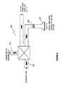
- the energy processing unit comprises a conduit 55 for bringing warm air from the solar collectors 1 to the energy processing unit, an air/water heat exchanger 51, a conduit 56 for carrying water from the energy processing unit to around the house, dampers 52,54 for controlling the direction of air flow, a conduit 57 for carrying air to supply the house and a conduit 58 for carrying air extracted from the house to the fan 53 and a conduit 59 for carrying air from the energy processing unit back to the solar collectors 1.
- the energy processing unit also includes a heat recovery unit 60 which comprises an air/air heat exchanger.
- the heat recovery unit 60 is linked to the energy processing unit via conduits 61,62 and air from atmosphere can enter the unit 60 via conduit 63 and air exits from the unit 60 to atmosphere via conduit 64.
- the air/air heat exchanger is a cross flow type heat exchanger made up of aluminium plates across which heat exchange occurs between warmer and cooler air streams.
- Heated air collected by the solar panels 1 is pumped into the energy processing unit 50' via conduit 55 and enters an air/water heat exchanger 51 where the heat energy from the air is transferred to the cooler water in the heat exchanger 51, thereby warming the water in the heat exchanger 51.
- the air emerging from the heat exchanger may
- dampers 52,54 respectively effectively controls the temperature of water and air supplied to the house since for example in option (c), warm air entering from the solar collectors 1 will obviously result in warmer water emerging from the heat exchanger 51.
- conduits 63 and 62 When the fan 53 is operating, air in the system is continuously being refreshed through conduits 63 and 62 with a feed of fresh air, with approximately 10% of air being dumped to atmosphere through conduits 61 and 64 which provide the bleeding of air from the system at generally the same rate as the feed of air.
- Warm water which emerges from the heat exchanger 51 is carried from the energy processing unit 50 via conduit 56. This warm water can be pumped to the standard household hot water cylinder 120 via conduit 106. Water emerging from the cylinder 120 is carried via conduit 107. Alternatively, if the water emerging from the energy processing unit 50 is not hot enough for household use, it can be pumped to the boiler 100 where it is heated and then subsequently pumped to the cylinder 120. Air is extracted from the house via extractor unit 58a and enters the fan 53 in the energy processing unit 50.
- control means used to or-ordinate and control the components and functions of the embodiments of the invention is not described in detail as it can be one of a number of control devices currently available on the market for heating and ventilation systems. Typically, it will include a control panel for use by the user, one or more thermostats throughout the house, a programmable logic controller, various transducers and relays for opening and closing valves and dampers and generally controlling the electrically operated components of the system.
Landscapes
- Engineering & Computer Science (AREA)
- Chemical & Material Sciences (AREA)
- Mechanical Engineering (AREA)
- Sustainable Development (AREA)
- Sustainable Energy (AREA)
- Thermal Sciences (AREA)
- Physics & Mathematics (AREA)
- Combustion & Propulsion (AREA)
- Life Sciences & Earth Sciences (AREA)
- General Engineering & Computer Science (AREA)
- Photovoltaic Devices (AREA)
- Central Heating Systems (AREA)
- Central Air Conditioning (AREA)
- Details Of Aerials (AREA)
- Roof Covering Using Slabs Or Stiff Sheets (AREA)
Claims (9)
- Lufterhitzungs- und Wärmerückgewinnungsventilationssystem, umfassend
einen oder mehrere Sonnenkollektoren (1) zum Absorbieren und Speichern von Sonnenenergie während der Stunden mit Tageslicht;
eine Energieverarbeitungseinheit (50) zum Kombinieren und Verteilen von Energie aus verschiedenen Quellen;
einen Boiler (100), der mit dem System über die Energieverarbeitungseinheit verbunden ist;
ein Steuermittel (25), das ein Mittel zum Koordinieren und Steuern aller Komponenten und Funktionen des Systems vorsieht; und
ein Luftverteilungssystem, das ermöglicht, Wärme in einem Haus über ein Netzwerk von Leitungen zu verteilen,
wobei die Energieverarbeitungseinheit (50) eine Luftbehandlungseinheit (105) reguliert, die einen Luft-Wasser-Wärmetauscher (151) und Mittel zum Zwingen der erhitzten Luft von den Sonnenkollektoren (1) durch den Wärmetauscher (151), wodurch Wärme auf Wasser in dem Haushaltsheißwasserversorgungssystem übertragen ist, und zum Zwingen von warmer Luft, die aus dem Wärmetauscher (151) entweicht, zum Strömen durch das Haus umfasst,
dadurch gekennzeichnet, dass die Energieverarbeitungseinheit (50) ein Gehäuse (106) mit vier Kammern (111, 112, 113, 114) umfasst, wobei jede Kammer eine Öffnung aufweist, wobei die erste Kammer (111) die Frischluftaufnahmekammer ist und Mittel zum Steuern und Anhalten des Aufnehmens von Frischluft aufweist,
eine zweite Kammer (112) die Kammer ist, welche Luft zum Sonnenkollektor leitet und ein Gebläse (153) zum Zwingen von Luft durch das System aufweist;
eine dritte Kammer (113) die Kammer ist, die Luft empfängt, welche von dem Sonnenkollektor zurückströmt und Mittel zum Steuern und Anhalten des Luftstroms von dem Sonnenkollektor (1) aufweist; und
eine vierte Kammer (114) die Kammer ist, welche erwärmte Luft zum Haus leitet und den Luft-Wasser-Wärmetauscher (151) aufweist, und
das Steuermittel in der ersten Kammer (111) einen ersten Schieber (171) umfasst, der zwischen einer offenen und einer geschlossenen Position beweglich ist, wobei der erste Schieber in der geschlossenen Position die Luftaufnahme in die Einheit blockiert und eine Verbindung zwischen der ersten und vierten Kammer (111, 114) ermöglicht, und wobei das Steuermittel in der dritten Kammer einen zweiten Schieber (170) umfasst, der zwischen einer offenen und einer geschlossenen Position beweglich ist, wobei der zweite Schieber (170) in der geschlossenen Position den Luftstrom von dem Sonnenkollektor (1) blockiert und eine Verbindung zwischen der zweiten und dritten Kammer (112, 113) ermöglicht. - Lufterhitzungs- und Wärmerückgewinnungsventilationssystem nach Anspruch 1, wobei die Luftbehandlungseinheit einen Luft-Luft-Wärmetauscher (110) zum Entziehen von Wärme aus Luft, die von dem Haus zurückströmt, beinhaltet.
- Lufterhitzungs- und Wärmerückgewinnungsventilationssystem nach Anspruch 2, wobei die Luft, die von dem Haus zurückströmt, durch eine Leitung (155) strömt, die von der Leitung getrennt ist, die erwärmte Luft zum Haus leitet, und Mittel zum Ausstoßen der gesamten Luft, die von dem Haus zurückströmt, nachdem sie durch den Luft-Luft-Wärmetauscher (110) geströmt ist, vorsieht.
- Lufterhitzungs- und Wärmerückgewinnungsventilationssystem nach Anspruch 2, wobei die Luft, die von dem Haus zurückströmt, durch eine Leitung (155) strömt, die das Vermischen mit Frischluft vorsieht, welche in das System eintritt, und Mittel zum Ausstoßen eines Teils der vermischten Luft, nachdem sie durch den Luft-Luft-Wärmetauscher (110) geströmt ist, vorsieht.
- Lufterhitzungs- und Wärmerückgewinnungsventilationssystem nach Anspruch 1, wobei der Boiler (100) zum Zuführen von heißem Wasser an den Luft-Wasser-Wärmetauscher (151) in der vierten Kammer (114) der Energieverarbeitungseinheit betriebsbereit ist; wobei die Luft, die zum Haus geleitet ist, durch den Luft-Wasser-Wärmetauscher (151) erhitzt sein kann.
- Lufterhitzungs- und Wärmerückgewinnungsventilationssystem nach einem der vorhergehenden Ansprüche, wobei der Sonnenkollektor (1) ein verlängertes Gehäuse, das eine Sonnenstrahlungsdurchlassabdeckung (7) und einen reflektierenden Unterbau (4) beinhaltet, die in räumlich getrennter Beziehung durch Seiten- und Endglieder (la, 1b) gehalten sind, einen Sonnenstrahlungsabsorber (6) in dem Gehäuse, Einlassmittel, die ermöglichen, dass Fluid an einem Ende des Gehäuses in den Absorber (6) eintritt, und Auslassmittel, die ermöglichen, dass das Fluid an einem entgegengesetzten Ende des Gehäuses aus dem Absorber (6) austritt, umfasst; dadurch gekennzeichnet, dass die Sonnenstrahlungsdurchlassabdeckung (7) eine Scheibe aus vorgespanntem Glas umfasst, auf deren Unterseite eine Beschichtung aufgetragen ist, wobei die Beschichtung einen niedrigen Ausstrahlungswert ("niedrigen E-Wert") aufweist.
- Lufterhitzungs- und Wärmerückgewinnungsventilationssystem nach Anspruch 6, wobei die Abdeckung (7) vom Sonnenstrahlungsabsorber (6) räumlich getrennt ist und dazwischen eine Zwischenschicht angeordnet ist, wobei die Zwischenschicht einen Luftspalt (11) beinhaltet, der von der Abdeckung räumlich getrennt ist.
- Lufterhitzungs- und Wärmerückgewinnungsventilationssystem nach Anspruch 7, wobei eine Schicht von transparenter Verkleidung (10) zum Definieren des Luftspalts (11) von der Abdeckung (7) räumlich getrennt ist, um eine "doppelt verglaste" Sonnenkollektorenspeicherung vorzusehen.
- Lufterhitzungs- und Wärmerückgewinnungsventilationssystem nach Anspruch 8, wobei die Schicht von transparenter Verkleidung (10) eine Schicht von Polytetrafluorethylen (PTFE) umfasst.
Applications Claiming Priority (3)
| Application Number | Priority Date | Filing Date | Title |
|---|---|---|---|
| IE950113 | 1995-02-13 | ||
| IE950113 | 1995-02-13 | ||
| PCT/IE1996/000006 WO1996025632A1 (en) | 1995-02-13 | 1996-02-13 | Improved solar panel and air heating and heat recovery ventilation system |
Publications (2)
| Publication Number | Publication Date |
|---|---|
| EP0808441A1 EP0808441A1 (de) | 1997-11-26 |
| EP0808441B1 true EP0808441B1 (de) | 2004-10-06 |
Family
ID=11040664
Family Applications (1)
| Application Number | Title | Priority Date | Filing Date |
|---|---|---|---|
| EP96902419A Expired - Lifetime EP0808441B1 (de) | 1995-02-13 | 1996-02-13 | Luftheizung und belüftungssystem mit wärmerückgewinnung mit sonnenkollektoren |
Country Status (5)
| Country | Link |
|---|---|
| EP (1) | EP0808441B1 (de) |
| AT (1) | ATE278915T1 (de) |
| AU (1) | AU4674696A (de) |
| DE (1) | DE69633558D1 (de) |
| WO (1) | WO1996025632A1 (de) |
Families Citing this family (6)
| Publication number | Priority date | Publication date | Assignee | Title |
|---|---|---|---|---|
| EP1376027B1 (de) * | 2002-06-26 | 2018-01-24 | NuAire Limited | Verbesserungen zu Sonnenpaneelen |
| AU2003900506A0 (en) * | 2003-02-05 | 2003-02-20 | Curtis, Paul F Mr | Heat and power solar tiles |
| CA2672180A1 (en) | 2006-12-11 | 2008-06-19 | To Ip Holding Company Pty Ltd. | Heating and cooling system |
| CN101319820B (zh) * | 2007-06-08 | 2010-12-22 | 富准精密工业(深圳)有限公司 | 自然空调装置 |
| ES2581677T3 (es) | 2009-01-29 | 2016-09-06 | Tata Steel Uk Limited | Aparato para calentamiento utilizando energía solar y método de calentamiento utilizando energía solar |
| FR2963088B1 (fr) * | 2010-07-24 | 2012-08-03 | Serge Estrade | Systeme d'activation du transfert thermique d'une extension solaire a un batiment attenant et extension solaire equipee d'un tel systeme |
Family Cites Families (9)
| Publication number | Priority date | Publication date | Assignee | Title |
|---|---|---|---|---|
| US4721349A (en) * | 1974-08-16 | 1988-01-26 | Massachusetts Institute Of Technology | Transparent heat-mirror |
| DE2600882A1 (de) * | 1976-01-12 | 1977-07-21 | Philips Patentverwaltung | Flacher sonnenkollektor |
| US4129116A (en) * | 1976-10-22 | 1978-12-12 | Solar Control Corporation | Solar air flow controller and system |
| GB2046895A (en) * | 1979-04-12 | 1980-11-19 | Solar Energy Developments | Apparatus for the circulation of fluid for use in heating and cooling system |
| FR2476806A1 (fr) * | 1980-02-25 | 1981-08-28 | Studelec Etu Installa Gles Ind | Maison solaire a captage et chauffage d'ambiance a air |
| FR2492955A1 (fr) * | 1980-10-27 | 1982-04-30 | Furio Habitat Solaire Sarl | Chauffage central solaire a air d'un batiment |
| FR2522122B1 (fr) * | 1982-02-23 | 1987-02-27 | Forclum Force Lumiere Elect | Dispositif de ventilation automatique |
| GB8515811D0 (en) * | 1985-06-21 | 1985-07-24 | Finsun En Ab | Thermally insulating glazing |
| IE64906B1 (en) * | 1989-02-24 | 1995-09-20 | Bq Technology Limited | Solar panel |
-
1996
- 1996-02-13 EP EP96902419A patent/EP0808441B1/de not_active Expired - Lifetime
- 1996-02-13 DE DE69633558T patent/DE69633558D1/de not_active Expired - Lifetime
- 1996-02-13 AU AU46746/96A patent/AU4674696A/en not_active Abandoned
- 1996-02-13 WO PCT/IE1996/000006 patent/WO1996025632A1/en not_active Ceased
- 1996-02-13 AT AT96902419T patent/ATE278915T1/de not_active IP Right Cessation
Also Published As
| Publication number | Publication date |
|---|---|
| WO1996025632A1 (en) | 1996-08-22 |
| ATE278915T1 (de) | 2004-10-15 |
| EP0808441A1 (de) | 1997-11-26 |
| AU4674696A (en) | 1996-09-04 |
| DE69633558D1 (de) | 2004-11-11 |
Similar Documents
| Publication | Publication Date | Title |
|---|---|---|
| US3894685A (en) | Solar heating system | |
| US4103825A (en) | Solar heated and cooled dwelling | |
| US4147300A (en) | Method and structure for solar heating | |
| US5855320A (en) | Combined furnace and heat recovery system | |
| US3946720A (en) | Solar heat collector | |
| NO339407B1 (no) | Varmepumpesystem | |
| US3946721A (en) | Method of collecting and storing solar heat | |
| JP3797685B2 (ja) | 建物の暖房装置 | |
| EP0808441B1 (de) | Luftheizung und belüftungssystem mit wärmerückgewinnung mit sonnenkollektoren | |
| US3991937A (en) | Solar-heated unit | |
| KR200408782Y1 (ko) | 태양열 집열기를 이용한 난방장치 | |
| US4471758A (en) | House siding solar panel | |
| CA1213255A (en) | Air heating and ventilation system | |
| IES69476B2 (en) | Improved solar panel and air heating and heat recovery ventilation system | |
| KR200316737Y1 (ko) | 태양열난방시스템 | |
| US4078603A (en) | Solar collector and heating and cooling system | |
| RU2078289C1 (ru) | Тепловой пункт | |
| US4138061A (en) | Solar heating system | |
| GB2373849A (en) | Ventilation heat exchanger | |
| CA2750261A1 (en) | Heating apparatus using solar energy and method of heating using solar energy | |
| EP1407198B1 (de) | Lüftungsanlage | |
| US4353353A (en) | Low temperature solar furnace and method | |
| CN1534246A (zh) | 水源热泵恒温恒湿机组 | |
| JPS57157959A (en) | Ventilator | |
| CN201407756Y (zh) | 一种温度和湿度控制集成机组 |
Legal Events
| Date | Code | Title | Description |
|---|---|---|---|
| PUAI | Public reference made under article 153(3) epc to a published international application that has entered the european phase |
Free format text: ORIGINAL CODE: 0009012 |
|
| 17P | Request for examination filed |
Effective date: 19970912 |
|
| AK | Designated contracting states |
Kind code of ref document: A1 Designated state(s): AT BE CH DE DK ES FR GB GR IE IT LI LU MC NL PT SE |
|
| 17Q | First examination report despatched |
Effective date: 19980528 |
|
| RTI1 | Title (correction) |
Free format text: AIR HEATING AND HEAT RECOVERY VENTILATION SYSTEM WITH SOLAR PANELS |
|
| RTI1 | Title (correction) |
Free format text: AIR HEATING AND HEAT RECOVERY VENTILATION SYSTEM WITH SOLAR PANELS |
|
| RTI1 | Title (correction) |
Free format text: AIR HEATING AND HEAT RECOVERY VENTILATION SYSTEM WITH SOLAR PANELS |
|
| GRAH | Despatch of communication of intention to grant a patent |
Free format text: ORIGINAL CODE: EPIDOS IGRA |
|
| GRAS | Grant fee paid |
Free format text: ORIGINAL CODE: EPIDOSNIGR3 |
|
| GRAA | (expected) grant |
Free format text: ORIGINAL CODE: 0009210 |
|
| AK | Designated contracting states |
Kind code of ref document: B1 Designated state(s): AT BE CH DE DK ES FR GB GR IE IT LI LU MC NL PT SE |
|
| PG25 | Lapsed in a contracting state [announced via postgrant information from national office to epo] |
Ref country code: NL Free format text: LAPSE BECAUSE OF FAILURE TO SUBMIT A TRANSLATION OF THE DESCRIPTION OR TO PAY THE FEE WITHIN THE PRESCRIBED TIME-LIMIT Effective date: 20041006 Ref country code: LI Free format text: LAPSE BECAUSE OF FAILURE TO SUBMIT A TRANSLATION OF THE DESCRIPTION OR TO PAY THE FEE WITHIN THE PRESCRIBED TIME-LIMIT Effective date: 20041006 Ref country code: IT Free format text: LAPSE BECAUSE OF FAILURE TO SUBMIT A TRANSLATION OF THE DESCRIPTION OR TO PAY THE FEE WITHIN THE PRE;WARNING: LAPSES OF ITALIAN PATENTS WITH EFFECTIVE DATE BEFORE 2007 MAY HAVE OCCURRED AT ANY TIME BEFORE 2007. THE CORRECT EFFECTIVE DATE MAY BE DIFFERENT FROM THE ONE RECORDED.SCRIBED TIME-LIMIT Effective date: 20041006 Ref country code: FR Free format text: LAPSE BECAUSE OF NON-PAYMENT OF DUE FEES Effective date: 20041006 Ref country code: CH Free format text: LAPSE BECAUSE OF FAILURE TO SUBMIT A TRANSLATION OF THE DESCRIPTION OR TO PAY THE FEE WITHIN THE PRESCRIBED TIME-LIMIT Effective date: 20041006 Ref country code: BE Free format text: LAPSE BECAUSE OF FAILURE TO SUBMIT A TRANSLATION OF THE DESCRIPTION OR TO PAY THE FEE WITHIN THE PRESCRIBED TIME-LIMIT Effective date: 20041006 Ref country code: AT Free format text: LAPSE BECAUSE OF FAILURE TO SUBMIT A TRANSLATION OF THE DESCRIPTION OR TO PAY THE FEE WITHIN THE PRESCRIBED TIME-LIMIT Effective date: 20041006 |
|
| REG | Reference to a national code |
Ref country code: GB Ref legal event code: FG4D |
|
| REG | Reference to a national code |
Ref country code: CH Ref legal event code: EP |
|
| REG | Reference to a national code |
Ref country code: IE Ref legal event code: FG4D |
|
| REF | Corresponds to: |
Ref document number: 69633558 Country of ref document: DE Date of ref document: 20041111 Kind code of ref document: P |
|
| PG25 | Lapsed in a contracting state [announced via postgrant information from national office to epo] |
Ref country code: SE Free format text: LAPSE BECAUSE OF FAILURE TO SUBMIT A TRANSLATION OF THE DESCRIPTION OR TO PAY THE FEE WITHIN THE PRESCRIBED TIME-LIMIT Effective date: 20050106 Ref country code: GR Free format text: LAPSE BECAUSE OF FAILURE TO SUBMIT A TRANSLATION OF THE DESCRIPTION OR TO PAY THE FEE WITHIN THE PRESCRIBED TIME-LIMIT Effective date: 20050106 Ref country code: DK Free format text: LAPSE BECAUSE OF FAILURE TO SUBMIT A TRANSLATION OF THE DESCRIPTION OR TO PAY THE FEE WITHIN THE PRESCRIBED TIME-LIMIT Effective date: 20050106 |
|
| PG25 | Lapsed in a contracting state [announced via postgrant information from national office to epo] |
Ref country code: DE Free format text: LAPSE BECAUSE OF FAILURE TO SUBMIT A TRANSLATION OF THE DESCRIPTION OR TO PAY THE FEE WITHIN THE PRESCRIBED TIME-LIMIT Effective date: 20050108 |
|
| PG25 | Lapsed in a contracting state [announced via postgrant information from national office to epo] |
Ref country code: ES Free format text: LAPSE BECAUSE OF FAILURE TO SUBMIT A TRANSLATION OF THE DESCRIPTION OR TO PAY THE FEE WITHIN THE PRESCRIBED TIME-LIMIT Effective date: 20050117 |
|
| PG25 | Lapsed in a contracting state [announced via postgrant information from national office to epo] |
Ref country code: LU Free format text: LAPSE BECAUSE OF NON-PAYMENT OF DUE FEES Effective date: 20050213 |
|
| PG25 | Lapsed in a contracting state [announced via postgrant information from national office to epo] |
Ref country code: MC Free format text: LAPSE BECAUSE OF NON-PAYMENT OF DUE FEES Effective date: 20050228 |
|
| RAP2 | Party data changed (patent owner data changed or rights of a patent transferred) |
Owner name: KOLLECTAIRE TECHNOLOGY LIMITED |
|
| NLV1 | Nl: lapsed or annulled due to failure to fulfill the requirements of art. 29p and 29m of the patents act | ||
| REG | Reference to a national code |
Ref country code: CH Ref legal event code: PL |
|
| PLBE | No opposition filed within time limit |
Free format text: ORIGINAL CODE: 0009261 |
|
| STAA | Information on the status of an ep patent application or granted ep patent |
Free format text: STATUS: NO OPPOSITION FILED WITHIN TIME LIMIT |
|
| 26N | No opposition filed |
Effective date: 20050707 |
|
| EN | Fr: translation not filed | ||
| PGFP | Annual fee paid to national office [announced via postgrant information from national office to epo] |
Ref country code: IE Payment date: 20060227 Year of fee payment: 11 |
|
| GBPC | Gb: european patent ceased through non-payment of renewal fee |
Effective date: 20070213 |
|
| REG | Reference to a national code |
Ref country code: IE Ref legal event code: MM4A |
|
| PG25 | Lapsed in a contracting state [announced via postgrant information from national office to epo] |
Ref country code: PT Free format text: LAPSE BECAUSE OF NON-PAYMENT OF DUE FEES Effective date: 20050306 |
|
| PG25 | Lapsed in a contracting state [announced via postgrant information from national office to epo] |
Ref country code: IE Free format text: LAPSE BECAUSE OF NON-PAYMENT OF DUE FEES Effective date: 20070213 |
|
| PG25 | Lapsed in a contracting state [announced via postgrant information from national office to epo] |
Ref country code: GB Free format text: LAPSE BECAUSE OF NON-PAYMENT OF DUE FEES Effective date: 20070213 |
|
| PGFP | Annual fee paid to national office [announced via postgrant information from national office to epo] |
Ref country code: GB Payment date: 20060228 Year of fee payment: 11 |