EP0808601A2 - Ustensile de nettoyage, en particulier pour frotter par voie humide - Google Patents
Ustensile de nettoyage, en particulier pour frotter par voie humide Download PDFInfo
- Publication number
- EP0808601A2 EP0808601A2 EP97107936A EP97107936A EP0808601A2 EP 0808601 A2 EP0808601 A2 EP 0808601A2 EP 97107936 A EP97107936 A EP 97107936A EP 97107936 A EP97107936 A EP 97107936A EP 0808601 A2 EP0808601 A2 EP 0808601A2
- Authority
- EP
- European Patent Office
- Prior art keywords
- cleaning
- wiper plate
- cleaning element
- fabric
- cleaning device
- Prior art date
- Legal status (The legal status is an assumption and is not a legal conclusion. Google has not performed a legal analysis and makes no representation as to the accuracy of the status listed.)
- Granted
Links
Images


Classifications
-
- A—HUMAN NECESSITIES
- A47—FURNITURE; DOMESTIC ARTICLES OR APPLIANCES; COFFEE MILLS; SPICE MILLS; SUCTION CLEANERS IN GENERAL
- A47L—DOMESTIC WASHING OR CLEANING; SUCTION CLEANERS IN GENERAL
- A47L13/00—Implements for cleaning floors, carpets, furniture, walls, or wall coverings
- A47L13/10—Scrubbing; Scouring; Cleaning; Polishing
- A47L13/20—Mops
- A47L13/24—Frames for mops; Mop heads
- A47L13/254—Plate frames
- A47L13/256—Plate frames for mops made of cloth
-
- A—HUMAN NECESSITIES
- A47—FURNITURE; DOMESTIC ARTICLES OR APPLIANCES; COFFEE MILLS; SPICE MILLS; SUCTION CLEANERS IN GENERAL
- A47L—DOMESTIC WASHING OR CLEANING; SUCTION CLEANERS IN GENERAL
- A47L13/00—Implements for cleaning floors, carpets, furniture, walls, or wall coverings
- A47L13/10—Scrubbing; Scouring; Cleaning; Polishing
- A47L13/42—Details
- A47L13/46—Securing scouring or polishing cloths or sponges to the handles by gripping means, tongs, or the like
-
- A—HUMAN NECESSITIES
- A47—FURNITURE; DOMESTIC ARTICLES OR APPLIANCES; COFFEE MILLS; SPICE MILLS; SUCTION CLEANERS IN GENERAL
- A47L—DOMESTIC WASHING OR CLEANING; SUCTION CLEANERS IN GENERAL
- A47L13/00—Implements for cleaning floors, carpets, furniture, walls, or wall coverings
- A47L13/10—Scrubbing; Scouring; Cleaning; Polishing
- A47L13/50—Auxiliary implements
- A47L13/58—Wringers for scouring pads, mops, or the like, combined with buckets
Definitions
- the present invention relates to a cleaning device, in particular for wet and wet wiping, with a support group which has a handle and a wiping plate, and with a cleaning element which can be fastened to a wiping plate to form at least one connecting region in such a way that it is at least partially separated from it is pivotable away.
- a cleaning element of a mop consists, for example, of a multiplicity of absorbent fabric strips or a multiplicity of absorbent yarns, which are fastened together at the end of a broomstick.
- the dampened fabric strips or yarns bind soil dirt when they are moved over a floor to be cleaned. After cleaning the floor, the fabric strips or the yarns are immersed in clean cleaning liquid such as cleaning water and rinsed out.
- the German utility model G 84 17 307.6 discloses a hollow sieve to be placed on a commercially available cleaning bucket, into which a mop can be inserted, the fabric strips of which have soaked with cleaning liquid.
- the user of the mop exerts a pressure from above by pressing the handle of the mop into the hollow screen onto the fabric strips, so that they are pressed together in the hollow screen.
- the cleaning liquid contained in the fabric strips pressed out so that it can flow into the bucket provided under the hollow sieve.
- This solution has the disadvantage that a large force is required to squeeze out the fabric strips of the mop. Furthermore, there is always the risk of disadvantageous deformation of the hollow screen or the undesired knocking over of the cleaning bucket.
- a further development of the aforementioned hollow sieve whereby according to this further development the force required to express the fabric strips of the mop is reduced.
- a hollow screen is provided, which can be deformed transversely to the pressing direction as a result of the force acting when the fabric strips are pressed into the hollow screen, reducing its clear width and compressing the fabric strips of the mop.
- the pressing force acting in the pressing-in direction of the mop is also converted into a component acting laterally on the fabric strips of the mop.
- a disadvantage of the aforementioned hollow screen is that it is particularly susceptible to malfunctions due to its additional mobility. So it often happens that the hollow sieve is pressed through a holder essential for the compression.
- the hollow sieve frequently gets stuck to the tissue strips of the mop after pulling out the fabric strips of the mop and subsequently falls into the bucket for the cleaning liquid provided under the hollow sieve.
- the two aforementioned malfunctions restrict the suitability of the known wet wiping system to a considerable extent.
- a generic cleaning device has a support group or a mop holder which has a handle or a handle and a wiper plate.
- the wiper plate is divided in the middle in the area of the attachment of the handle in such a way that two jointly movable wiper plate halves are formed which fold down like wings when the support group is lifted.
- a flat cleaning element or a mop cover is attached to each outer end of a wiper plate half that points away from the common center.
- the wiper plate halves of the wiper plate collapse along their movable center line, so that the cleaning element is carried only by the fabric strips provided at the ends of the wiper plate half, forming an arc from the ends of the Wiper plate halves hanging down.
- the cleaning element can be inserted into a lever press, wherein the cleaning liquid present in the cleaning element can subsequently be squeezed out.
- the generic cleaning device is particularly disadvantageous that an expensive and space-consuming lever press must be available for pressing out the cleaning element.
- Another disadvantage is that the cleaning element must be attached to the wiper plate in a cumbersome manner.
- the structure of the generic cleaning device is also complicated, so that its operation is cumbersome.
- the wiper plate has a contact surface in at least one holding area, which is designed such that the cleaning element can be compressed between the contact surface and at least one counter surface when pivoted away from the wiper plate.
- the cleaning element configured as mentioned above, it is particularly easy to squeeze out the cleaning liquid contained in the cleaning element, which in particular has a sponge, a tissue, such as cloths or rags, yarns or by bundles of the aforementioned cleaning elements.
- the invention is based on the idea that the force applied by the user of the cleaning device can be converted particularly effectively into a pressing force for pressing out the cleaning element by means of a special contact surface.
- the counter surface is in particular formed by another object, such as through the bottom of a bucket or through a hollow sieve known in the prior art. Furthermore, it is conceivable that the counter surface is itself formed by the floor surface to be cleaned.
- the cleaning element provided on the device configured as mentioned above can be pressed out in a particularly simple and easy manner, the pressing out being particularly easy to start when the contact surface is arranged substantially perpendicular to the surface of the wiper plate facing the cleaning element and is just trained.
- an inclined arrangement of the contact surface with respect to the surface of the wiper plate is also possible.
- a clamping device is designed to fasten the cleaning element to the wiper plate, the clamping device being able to have a releasable clamping strip which interacts with a counter strip.
- the cleaning element can be fastened in a particularly simple manner between a detachable clamping strip and a counter strip by inserting it between the clamping strip and the clamping strip detached therefrom, whereupon the cleaning element is clamped between the clamping strip and counter strip.
- the clamping bar is pivotally articulated on the counter bar, at least one locking device for the releasable connection of the clamping and Counter bar is provided, which can also be designed as a snap connection or as a hook connection. This considerably simplifies the operation of the clamping device.
- the cleaning device according to the invention can be operated more easily if the support group additionally has a connecting element for connecting the handle and the wiper plate, the connecting element in particular being able to have a joint which can be pivoted in one plane.
- the joint can also be pivotable in two planes, as is the case when the joint is designed as a double joint.
- a particularly simple operation of the cleaning device according to the invention results when the joint is arranged in the area of the center of gravity of the wiper plate, it being particularly advantageous if the joint is arranged such that the wiper plate is raised when the handle is raised and when the wiper plate is pivoted away State of the cleaning element is substantially between the handle and cleaning element. In this state, the cleaning element is at the bottom, while essentially only the wiper plate extends between the handle and the cleaning element.
- the cleaning element located under the wiping plate can be quickly pressed together, whereby simple operation and effective pressing out of the cleaning element is achieved without the cleaning element having to be touched by hand.
- a fastening assembly is provided in the connecting element with which the handle can be attached. This can be achieved, for example, by means of a screw thread, a clamp connection or a transverse bore with a pin which can be fastened in a broom handle in particular.
- a particularly advantageous embodiment of the wiper plate has an essentially trapezoidal outline.
- a cleaning device with a wiper plate with the aforementioned layout is suitable for easy and precise cleaning of hidden surfaces. It increases the stability of the cleaning device according to the invention when the Wiper plate on its side facing away from the cleaning element has stiffening elements, in particular in the form of stiffening ribs.
- a wiper plate designed as mentioned above can be manufactured particularly easily from plastic.
- a cleaning element according to the invention in particular a mop cover, which is intended in particular for use in a cleaning device according to one of claims 1 to 22, has an essentially flat base fabric and a cleaning fabric provided on one side of the base fabric, both a base fabric section with cleaning fabric and a Basic fabric section without cleaning fabric is provided.
- the base fabric section which has no cleaning fabric, can be easily attached to the wiper plate due to its smaller thickness and because of its greater flexibility, especially if it has a clamping device according to the invention.
- the base fabric section with cleaning fabric can be designed as a pile fabric, the pile fabric having a pile with a pile length between 5 mm and 20 mm.
- the base fabric section with cleaning fabric can also have a fabric with tufted loops, it also being possible to provide a fabric with sewn-on fringe and / or loop webs.
- the aforementioned fabrics have particularly good cleaning properties, and cleaning-active textile fibers can also be used. These fibers can consist of natural fibers, such as cotton or viscose, or also of synthetic fibers, such as polyester or polyamide, or of combinations of the aforementioned types of fibers.
- the cleaning fabric according to the invention has in particular a section with a trapezoidal outline, which simplifies the cleaning of even hard-to-reach places.
- the cleaning element according to the invention can also have a section with a square outline, which can merge into an area which is designed such that the cleaning element in this area has a basic fabric section without cleaning fabric, with which the cleaning element, as already explained above, is particularly simple and reliable a clamping device can be attached. This enables simple handling of the cleaning element according to the invention and, in particular, secure attachment in the cleaning device according to the invention.
- the cleaning element can be pressed out in a particularly simple manner, with the cleaning device according to the invention making it possible to clean floors reliably and quickly.
- a secure connection of the squeeze basket with the container for the cleaning liquid is obtained when the squeeze basket has contact surfaces with hooks that can be hooked under the edge of a bucket. This counteracts an overturning of the bucket due to a careless movement of the user of the cleaning system according to the invention when the cleaning element is pressed out.
- the inventive method for pressing out the cleaning element achieves simple and reliable separation of the cleaning liquid present in the cleaning element.
- the cleaning device in particular for wet and wet wiping, has a supporting group with a handle and with a wiper plate and a cleaning element which can be connected to the wiper plate to form at least two connecting areas, wiper plate and the cleaning element are designed such that the cleaning element can be fastened to the wiper plate in at least a first connecting area such that they can be pivoted relative to one another, and the cleaning element and the wiping plate are designed in at least one second connecting area so that they are there on the wiper plate pivoted state of the cleaning element in the direction of the surface of the wiper plate facing the cleaning element together form a coherent connection, while in a direction transverse to the aforementioned surface, in particular in the sense of each other are flexible that it is possible to separate them in a simple manner.
- This special design of the cleaning device according to the invention ensures that the cleaning element is pivotally connected to the wiper plate in a first region, while the wiper plate in another region of the cleaning element is not firmly connected to the wiper plate, but in particular can only be brought into engagement with it .
- the condition in which the cleaning element is firmly engaged with the wiper plate is preferably present when the cleaning device according to the invention is in the cleaning position on a floor surface. Then it is ensured by the formation of the wiper plate and cleaning element that the cleaning element cannot move transversely to the surface of the wiper plate in the region in which the wiper plate engages with the cleaning element. This enables the cleaning element to be guided precisely on the floor to be cleaned.
- the cleaning element and wiper plate When the wiper plate is lifted from the floor surface to be cleaned, the cleaning element and wiper plate preferably detach themselves from one another, so that the cleaning element hanging freely from the wiper plate downward for pressing out the cleaning fluid stored in it can be used in a corresponding device without it as in wiping systems known in the prior art would have to be removed from the wiping plate. This avoids an expensive attachment of the cleaning element to the wiper plate while nevertheless, the cleaning element can be easily cleaned without having to touch it by hand.
- a particularly reliable function of the cleaning device according to the invention is obtained if a clamping device is designed to fasten the cleaning element to the wiper plate.
- This clamping device can be developed in particular in accordance with one of the claims 5 to 11 described above.
- the cleaning element has a base fabric and a cleaning fabric provided on the base fabric, both a base fabric section with cleaning fabric and a base fabric section without cleaning fabric being provided on both sides of the base fabric.
- the cleaning element has a base fabric and a cleaning fabric provided on the base fabric, both a base fabric section with cleaning fabric and a base fabric section without cleaning fabric being provided on both sides of the base fabric.
- the aforementioned design of the cleaning element also ensures that there is a coherent connection of the cleaning element with the wiper plate when the cleaning element is pivoted to the wiper plate, since the cleaning fabric provided on the base fabric then counteracts a lateral movement of the wiper plate. This counteracts a displacement of the wiper plate and cleaning element, so that the cleaning device according to the invention is easier to handle.
- the cleaning element is designed such that when the cleaning element is fastened in the clamping device and pivoted onto the wiper plate, the surface of the wiper plate facing the cleaning element is in contact with the cleaning fabric. Then the cleaning fabric located under the wiper plate is pressed together on the base fabric, while the upright cleaning fabric located next to it counteracts a lateral displacement of the wiper plate.
- the cleaning device according to the invention designed as above can be designed in accordance with claims 12 to 30 with regard to the connection of handle and wiper plate, with regard to the design of the wiper plate and with regard to the design of the cleaning element. It is also possible to use a cleaning device to provide, which in addition to the features of claims 34 to 39 also includes the features of claims 1 to 3. Such a cleaning device according to the invention combines the advantages of easy pressing out of the cleaning element with the advantages of easy handling during cleaning and when moving into a state before the cleaning element is pressed out.
- a cleaning element according to the invention can be produced particularly simply and inexpensively, the function in the cleaning device according to the invention and in the cleaning system according to the invention being ensured.
- a particularly wear-resistant cleaning element can be achieved if at least one binding tape and / or at least one binding seam are provided on the edges of the cleaning element during the course of production.
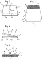
- Figure 1 shows a wiper device 1 according to the invention in side view.
- the mopping device 1 has a mop 2 which is carried by a mop holder 3. In the view shown in FIG. 1, the mop 2 lies on the surface 4 of a floor 5 to be cleaned.
- the mop 2 has a carrier fabric 6 to which a cleaning fabric 7 with tufted loops is applied on one side.
- the mop 2 is essentially divided into three areas. In a cleaning area 8, the cleaning fabric 7 is in contact with the surface 4 of the floor 5.
- a fastening area 9 of the mop 2 is provided, in which the mop 2 is connected to the mop holder 3.
- a contact area 10 of the mop 2 is also provided, in which the mop 2 has a double layer of base fabric 6 with cleaning fabric 7 and therefore also on its side facing away from the surface 4, cleaning fabric 7.
- the mop 2 is also connected to the mop holder 3 in the contact area 10.
- the mop 2 has an essentially trapezoidal outline, the narrower side of the trapezoid being provided on the side of the mop 2 facing away from the fastening region 9.
- the carrier fabric 6 is turned over and connected to the underside by gluing.
- cleaning fabric 7 is also provided in the contact area 10 on the top of the mop 2, which can be seen particularly well in this illustration.
- the fastening area 9 itself lying opposite the contact area 10 has a square outline.
- an edge strip cleaning area 11 which can be seen particularly well in this view, is provided, which also has a square outline.
- the mop holder 3 as can best be seen in FIG. 1 and in FIG. 3, has a wiper plate 12 which is provided with a rib 13 over part of its length.
- the wiper plate 12 is just large enough that the mop 2 protrudes in the operational state beyond the edges of the wiper plate 12.
- a clamping device 14 is provided on the wiper plate 12 with a counter strip 15 on the wiper plate side and a clamping strip 16 which is pivotably attached to the latter.
- the clamping device 14 is designed such that the fastening area 9 of the mop 2 can be firmly received in it.
- a handle holder 18 is pivotally attached via a pivot pin 17, which has a round receptacle 19 on its side facing away from the wiper plate 12 for receiving a handle 20.
- Fastening elements (not shown) for connecting the handle holder 19 and the handle 20 are also provided in this view.
- the clamping strip 16 which is pivotably attached to the counter strip 15 by a pivot pin 21, can be pivoted away from the counter strip 15 after a snap connection 22 has been released, so that the fastening region 9 of the mop 2 between Counter bar 15 and terminal block 16 can be inserted.
- the fastening area 9 of the mop 2 is inserted between the counter bar 15 and the clamping bar 16 until the edge bar cleaning area 11 of the mop 2 rests against the front edge of the clamping device 14, as can best be seen in FIG. 1 and in FIG. 5.
- both the counter bar 15 and the terminal block 16 are W-shaped in cross section.
- Mating bar 15 and clamping bar 16 are further designed so that they form a flat pressing surface 23 in abutting condition on their side facing away from the wiper plate 12, which is perpendicular to the lower surface of the wiper plate 12 facing the mop 2.
- the wiper plate 12 is also designed so that the handle 20 together with the handle holder 18 can be pivoted so far in the direction away from the clamping device 14 that the handle holder 18 rests on the top of the wiper plate 12.
- the wiper 1 is shown in three positions “I", “II” and “III".
- the view “I” shows the mopping device 1 after it has been placed on the floor 5 such that the mop 2 lies almost completely on the surface 4 of the floor while the mop holder 3 is not yet touching the top of the mop 2.
- the position “II” shows an intermediate state of the mop holder 3 on the way from state “I” to state “III”.
- state “III" which is also shown in FIG. 5
- the mop holder 3 is completely placed on the upper surface of the mop 2.
- the special type of fastening of the mop 2 in the clamping device 14 ensures that the edge strip cleaning area 11 of the mop 2 is located in the area of the pressing surface 23.
- this pressing surface 23 is perpendicular to the surface 4 of the base 5, which ensures that the edge strip cleaning area 11 of the mop 3 located above the pressing surface 23 is simple any edge strips of a wall not shown in the figures can be cleaned in the area of the base 5.
- FIG. 6, FIG. 7 and FIG. 8 show an extrusion basket 30 belonging to the wiper device 1, which is placed on a commercially available bucket 31.
- the squeezing basket 30 is made of plastic, and squeezing baskets of metal such as steel or aluminum, not shown in this view, are also provided.
- the squeeze basket 30 has a support surface 32 with hooks 33 on both sides, which include a bucket edge 34.
- the contact surfaces 32 and the hooks 33 are designed in such a way that the squeeze basket 30 can be placed on buckets with different diameters.
- the squeeze basket 30 has a funnel-shaped immersion opening 35 and runs slightly conically from the immersion opening 35 to a basket base 36.
- Side walls 37 are perforated with vertically extending grooves 38, while a plurality of drain holes 39 are made in the basket base 36.
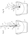
- the squeezing of the mop 2 in the squeeze basket 30 can best be seen in FIGS. 9 and 10.
- the mopping device 1 lifted off the floor with the mop holder 3 folded down and with the mop holder 2 adjoining the mop holder 3 is brought over the squeeze basket 30 and inserted into the immersion opening 35 from above, which is designated in FIG. 9 with the state “IV” .
- the wiping device 1 is pressed further into the squeeze basket 30 using a force F, so that the mop 2 folds like a fold.
- the mop 2 With the flat pressing surface 23, the mop 2 is now pressed together by pressure from above such that a cleaning liquid contained in the mop 2 can run through the grooves 38 in the side walls 37 into the bucket 31, as indicated in FIG. 10 with the state "V” .
- the relatively small pressing surface 23 results in a high pressure under the application of the force F and thus a squeezing result which is comparable to the manual wringing out of the mop 2.
- the squeezing basket 30 is designed such that the mop holder 3 with the mop 2 can be placed in the squeezing basket 30. On the one hand, this can be done in the pressed state "V". On the other hand, there is the possibility of not completely inserting the mop 2 into the squeeze basket 30, but rather hanging it over an edge 40 of the squeeze basket 30. Then the wiper device 1 is securely in the squeeze basket 30 without the wiper device 1 falling over.
Landscapes
- Cleaning Implements For Floors, Carpets, Furniture, Walls, And The Like (AREA)
- Inking, Control Or Cleaning Of Printing Machines (AREA)
- Cleaning Or Drying Semiconductors (AREA)
Applications Claiming Priority (2)
| Application Number | Priority Date | Filing Date | Title |
|---|---|---|---|
| DE19620633A DE19620633C2 (de) | 1996-05-22 | 1996-05-22 | Reinigungsgerät, insbesondere zum Feucht- und Naßwischen |
| DE19620633 | 1996-05-22 |
Publications (3)
| Publication Number | Publication Date |
|---|---|
| EP0808601A2 true EP0808601A2 (fr) | 1997-11-26 |
| EP0808601A3 EP0808601A3 (fr) | 2002-03-20 |
| EP0808601B1 EP0808601B1 (fr) | 2006-09-06 |
Family
ID=7795034
Family Applications (1)
| Application Number | Title | Priority Date | Filing Date |
|---|---|---|---|
| EP97107936A Expired - Lifetime EP0808601B1 (fr) | 1996-05-22 | 1997-05-15 | Ustensile de nettoyage, en particulier pour frotter par voie humide |
Country Status (7)
| Country | Link |
|---|---|
| EP (1) | EP0808601B1 (fr) |
| AT (1) | ATE338504T1 (fr) |
| DE (2) | DE19620633C2 (fr) |
| DK (1) | DK0808601T3 (fr) |
| ES (1) | ES2270447T3 (fr) |
| PL (1) | PL183974B1 (fr) |
| PT (1) | PT808601E (fr) |
Cited By (9)
| Publication number | Priority date | Publication date | Assignee | Title |
|---|---|---|---|---|
| WO2005117680A1 (fr) * | 2004-05-28 | 2005-12-15 | Carl Freudenberg Kg | Systeme d'essuyage, dispositif d'essorage et appareil d'essuyage |
| WO2006002653A1 (fr) * | 2004-06-29 | 2006-01-12 | Ecolab Inc. | Dispositif de lavage du sol pour laver des surfaces a nettoyer, support de balai de lavage du sol et housse de balai de lavage du sol pour dispositif de lavage du sol |
| USD528729S1 (en) | 2005-05-10 | 2006-09-19 | Rubbermaid Commerical Products Llc | Cart |
| USD529294S1 (en) | 2005-01-31 | 2006-10-03 | Rubbermaid Commercial Products Llc | Universal joint |
| USD533356S1 (en) | 2005-01-31 | 2006-12-12 | Rubbermaid Commercial Products Llc | Universal joint |
| USD547017S1 (en) | 2005-05-10 | 2007-07-17 | Rubbermaid Commercial Products Llc | Mop handle |
| USD548913S1 (en) | 2005-05-10 | 2007-08-14 | Rubbermaid Commercial Products Llc | Mop bucket and wringer |
| USD549414S1 (en) | 2005-01-31 | 2007-08-21 | Rubbermaid Commercial Products Llc | Mop frame |
| USD549912S1 (en) | 2007-01-12 | 2007-08-28 | Rubbermaid Commercial Products Llc | Mop |
Families Citing this family (2)
| Publication number | Priority date | Publication date | Assignee | Title |
|---|---|---|---|---|
| DE10210569B4 (de) | 2002-03-09 | 2009-09-24 | Carl Freudenberg Kg | Auswringvorrichtung für einen Flachwischer und Reinigungssystem |
| DE102010016813A1 (de) | 2010-05-05 | 2011-11-10 | Leifheit Ag | Auspresskorb für den Wischbezug eines Bodenwischers sowie Kombination eines Auspresskorbs mit einem Behälter |
Family Cites Families (15)
| Publication number | Priority date | Publication date | Assignee | Title |
|---|---|---|---|---|
| GB284625A (en) * | 1927-02-01 | 1929-03-07 | Adolf Barth | A cleaning device for floors |
| FR1129789A (fr) * | 1954-08-14 | 1957-01-25 | Dispositif pour le lavage des planchers et analogues | |
| US2851710A (en) * | 1954-09-08 | 1958-09-16 | Thomas F Leach | Mop and wringer therefor |
| US3531815A (en) * | 1968-08-02 | 1970-10-06 | Theron V Moss | Buffing device |
| US3924289A (en) * | 1974-11-14 | 1975-12-09 | Deering Milliken Res Corp | Wet mop head construction |
| FR2401645A1 (fr) * | 1977-09-01 | 1979-03-30 | Labernadie Germaine | Dispositif pour le lavage des sols |
| DE8128731U1 (de) * | 1981-10-01 | 1982-02-04 | Raab, Hans, 6602 Dudweiler | "auswechselbare textilbespannung, insbesondere fuer fussboden-feuchtreinigungsgeraete" |
| SE463594B (sv) * | 1989-05-24 | 1990-12-17 | Ulla Antionett Eriksson | Rengoeringsduk |
| FR2663832A1 (fr) * | 1990-07-02 | 1992-01-03 | Amir Guy | Moyens pour la fixation amovible d'un tampon de nettoyage a la tete d'un balai. |
| AT398527B (de) * | 1991-11-14 | 1994-12-27 | Frieb Eduard Gmbh | Reinigungsgerät bestehend aus einer bürste od.dgl. |
| SE500002C2 (sv) * | 1993-04-08 | 1994-03-21 | Gipeco Ab | Moppduk |
| WO1995022277A1 (fr) * | 1994-02-16 | 1995-08-24 | Margarete Burkhardt | Dispositif de nettoyage |
| US5461749A (en) * | 1994-05-31 | 1995-10-31 | Minnesota Mining And Manufacturing Company | Floor mop and cleaning system |
| DE9408885U1 (de) * | 1994-05-31 | 1994-09-01 | Meyer, Ingrid, 93155 Hemau | Wischbezug für Reinigungsgeräte |
| DE9415002U1 (de) * | 1994-09-15 | 1994-11-03 | Vileda GmbH, 69469 Weinheim | Bodenpflegegerät |
-
1996
- 1996-05-22 DE DE19620633A patent/DE19620633C2/de not_active Expired - Fee Related
-
1997
- 1997-05-15 DK DK97107936T patent/DK0808601T3/da active
- 1997-05-15 EP EP97107936A patent/EP0808601B1/fr not_active Expired - Lifetime
- 1997-05-15 DE DE59712722T patent/DE59712722D1/de not_active Expired - Lifetime
- 1997-05-15 ES ES97107936T patent/ES2270447T3/es not_active Expired - Lifetime
- 1997-05-15 AT AT97107936T patent/ATE338504T1/de active
- 1997-05-15 PT PT97107936T patent/PT808601E/pt unknown
- 1997-05-22 PL PL97320127A patent/PL183974B1/pl not_active IP Right Cessation
Cited By (10)
| Publication number | Priority date | Publication date | Assignee | Title |
|---|---|---|---|---|
| WO2005117680A1 (fr) * | 2004-05-28 | 2005-12-15 | Carl Freudenberg Kg | Systeme d'essuyage, dispositif d'essorage et appareil d'essuyage |
| US7917989B2 (en) | 2004-05-28 | 2011-04-05 | Carl Freudenberg Kg | Mop system, wringer device and mop |
| WO2006002653A1 (fr) * | 2004-06-29 | 2006-01-12 | Ecolab Inc. | Dispositif de lavage du sol pour laver des surfaces a nettoyer, support de balai de lavage du sol et housse de balai de lavage du sol pour dispositif de lavage du sol |
| USD529294S1 (en) | 2005-01-31 | 2006-10-03 | Rubbermaid Commercial Products Llc | Universal joint |
| USD533356S1 (en) | 2005-01-31 | 2006-12-12 | Rubbermaid Commercial Products Llc | Universal joint |
| USD549414S1 (en) | 2005-01-31 | 2007-08-21 | Rubbermaid Commercial Products Llc | Mop frame |
| USD528729S1 (en) | 2005-05-10 | 2006-09-19 | Rubbermaid Commerical Products Llc | Cart |
| USD547017S1 (en) | 2005-05-10 | 2007-07-17 | Rubbermaid Commercial Products Llc | Mop handle |
| USD548913S1 (en) | 2005-05-10 | 2007-08-14 | Rubbermaid Commercial Products Llc | Mop bucket and wringer |
| USD549912S1 (en) | 2007-01-12 | 2007-08-28 | Rubbermaid Commercial Products Llc | Mop |
Also Published As
| Publication number | Publication date |
|---|---|
| PL183974B1 (pl) | 2002-08-30 |
| ATE338504T1 (de) | 2006-09-15 |
| ES2270447T3 (es) | 2007-04-01 |
| DK0808601T3 (da) | 2006-11-20 |
| DE19620633C2 (de) | 1998-10-08 |
| PT808601E (pt) | 2006-12-29 |
| EP0808601A3 (fr) | 2002-03-20 |
| DE59712722D1 (de) | 2006-10-19 |
| PL320127A1 (en) | 1997-11-24 |
| EP0808601B1 (fr) | 2006-09-06 |
| DE19620633A1 (de) | 1997-11-27 |
Similar Documents
| Publication | Publication Date | Title |
|---|---|---|
| DE10102078C1 (de) | Auswringvorrichtung | |
| DE19631617C2 (de) | Mopbezug für einen Mophalter | |
| EP1263312B1 (fr) | Dispositif d'essuyage, dispositif d'essorage et systeme d'essuyage | |
| DE69936560T2 (de) | Kombination eines Eimers und einer Auswringvorrichtung | |
| EP0451443A1 (fr) | Instrument de nettoyage | |
| EP0808601B1 (fr) | Ustensile de nettoyage, en particulier pour frotter par voie humide | |
| EP0610838A1 (fr) | Dispositif pour nettoyer le sol | |
| DE4318792C2 (de) | Flächen-Feuchtreinigungseinrichtung | |
| EP1244378B1 (fr) | Structure absorbante destinee au nettoyage de surfaces | |
| DE4427672C2 (de) | Wischbezug für ein Naßreinigungsgerät | |
| DE10019211B4 (de) | Wischvorrichtung, Auspreßvorrichtung und Wischsystem | |
| EP0846438B1 (fr) | Outil pour essuyer un sol humide | |
| EP1210902B1 (fr) | Essoreuse de balai à franges | |
| EP1342445B1 (fr) | Balai de récurage | |
| DE20016042U1 (de) | Wischer | |
| EP1166706A1 (fr) | Tête de balai à frange | |
| EP1208789B1 (fr) | Outil pour essuyer un sol humide | |
| DE202017100484U1 (de) | Wischerplatte und Moppbezughalter mit Wischerplatte | |
| EP0823235A2 (fr) | Appareil extracteur de liquide | |
| DE10235308B4 (de) | Feuchtboden-Wischgerät | |
| EP4463046B1 (fr) | Dispositif de nettoyage | |
| DE19622265A1 (de) | Flächenwischgerät | |
| DE10235307A1 (de) | Feuchtboden-Wischgerät mit Auswringhülse | |
| DE19650868C2 (de) | Feuchtbodenwischgerät | |
| DE4303993C2 (de) | Fußbodenwischer |
Legal Events
| Date | Code | Title | Description |
|---|---|---|---|
| PUAI | Public reference made under article 153(3) epc to a published international application that has entered the european phase |
Free format text: ORIGINAL CODE: 0009012 |
|
| AK | Designated contracting states |
Kind code of ref document: A2 Designated state(s): AT BE CH DE DK ES FI FR GB GR IE IT LI LU MC NL PT SE |
|
| PUAL | Search report despatched |
Free format text: ORIGINAL CODE: 0009013 |
|
| RIC1 | Information provided on ipc code assigned before grant |
Free format text: 7A 47L 13/256 A |
|
| AK | Designated contracting states |
Kind code of ref document: A3 Designated state(s): AT BE CH DE DK ES FI FR GB GR IE IT LI LU MC NL PT SE |
|
| 17P | Request for examination filed |
Effective date: 20020524 |
|
| GRAP | Despatch of communication of intention to grant a patent |
Free format text: ORIGINAL CODE: EPIDOSNIGR1 |
|
| GRAS | Grant fee paid |
Free format text: ORIGINAL CODE: EPIDOSNIGR3 |
|
| GRAA | (expected) grant |
Free format text: ORIGINAL CODE: 0009210 |
|
| AK | Designated contracting states |
Kind code of ref document: B1 Designated state(s): AT BE CH DE DK ES FI FR GB GR IE IT LI LU MC NL PT SE |
|
| PG25 | Lapsed in a contracting state [announced via postgrant information from national office to epo] |
Ref country code: IT Free format text: LAPSE BECAUSE OF FAILURE TO SUBMIT A TRANSLATION OF THE DESCRIPTION OR TO PAY THE FEE WITHIN THE PRESCRIBED TIME-LIMIT;WARNING: LAPSES OF ITALIAN PATENTS WITH EFFECTIVE DATE BEFORE 2007 MAY HAVE OCCURRED AT ANY TIME BEFORE 2007. THE CORRECT EFFECTIVE DATE MAY BE DIFFERENT FROM THE ONE RECORDED. Effective date: 20060906 |
|
| REG | Reference to a national code |
Ref country code: GB Ref legal event code: FG4D Free format text: NOT ENGLISH |
|
| REG | Reference to a national code |
Ref country code: CH Ref legal event code: EP |
|
| GBT | Gb: translation of ep patent filed (gb section 77(6)(a)/1977) |
Effective date: 20060923 |
|
| REG | Reference to a national code |
Ref country code: IE Ref legal event code: FG4D Free format text: LANGUAGE OF EP DOCUMENT: GERMAN |
|
| REF | Corresponds to: |
Ref document number: 59712722 Country of ref document: DE Date of ref document: 20061019 Kind code of ref document: P |
|
| REG | Reference to a national code |
Ref country code: DK Ref legal event code: T3 |
|
| REG | Reference to a national code |
Ref country code: GR Ref legal event code: EP Ref document number: 20060403533 Country of ref document: GR |
|
| REG | Reference to a national code |
Ref country code: SE Ref legal event code: TRGR |
|
| REG | Reference to a national code |
Ref country code: CH Ref legal event code: NV Representative=s name: NOVAGRAAF INTERNATIONAL SA |
|
| REG | Reference to a national code |
Ref country code: PT Ref legal event code: SC4A Free format text: AVAILABILITY OF NATIONAL TRANSLATION Effective date: 20061012 |
|
| ET | Fr: translation filed | ||
| REG | Reference to a national code |
Ref country code: ES Ref legal event code: FG2A Ref document number: 2270447 Country of ref document: ES Kind code of ref document: T3 |
|
| PLBE | No opposition filed within time limit |
Free format text: ORIGINAL CODE: 0009261 |
|
| STAA | Information on the status of an ep patent application or granted ep patent |
Free format text: STATUS: NO OPPOSITION FILED WITHIN TIME LIMIT |
|
| 26N | No opposition filed |
Effective date: 20070607 |
|
| PGFP | Annual fee paid to national office [announced via postgrant information from national office to epo] |
Ref country code: PT Payment date: 20100507 Year of fee payment: 14 Ref country code: MC Payment date: 20100507 Year of fee payment: 14 Ref country code: LU Payment date: 20100518 Year of fee payment: 14 Ref country code: IE Payment date: 20100528 Year of fee payment: 14 Ref country code: FI Payment date: 20100518 Year of fee payment: 14 |
|
| PGFP | Annual fee paid to national office [announced via postgrant information from national office to epo] |
Ref country code: IT Payment date: 20100524 Year of fee payment: 14 |
|
| PGFP | Annual fee paid to national office [announced via postgrant information from national office to epo] |
Ref country code: SE Payment date: 20100518 Year of fee payment: 14 Ref country code: GB Payment date: 20100524 Year of fee payment: 14 |
|
| PGFP | Annual fee paid to national office [announced via postgrant information from national office to epo] |
Ref country code: GR Payment date: 20100526 Year of fee payment: 14 |
|
| REG | Reference to a national code |
Ref country code: CH Ref legal event code: PFA Owner name: VERMOP SALMON GMBH Free format text: VERMOP SALMON GMBH#KIESWEG 4-6#D-97877 WERTHEIM (DE) -TRANSFER TO- VERMOP SALMON GMBH#KIESWEG 4-6#D-97877 WERTHEIM (DE) |
|
| REG | Reference to a national code |
Ref country code: PT Ref legal event code: MM4A Free format text: LAPSE DUE TO NON-PAYMENT OF FEES Effective date: 20111115 |
|
| PG25 | Lapsed in a contracting state [announced via postgrant information from national office to epo] |
Ref country code: MC Free format text: LAPSE BECAUSE OF NON-PAYMENT OF DUE FEES Effective date: 20110531 |
|
| REG | Reference to a national code |
Ref country code: SE Ref legal event code: EUG |
|
| PG25 | Lapsed in a contracting state [announced via postgrant information from national office to epo] |
Ref country code: PT Free format text: LAPSE BECAUSE OF NON-PAYMENT OF DUE FEES Effective date: 20111115 Ref country code: FI Free format text: LAPSE BECAUSE OF NON-PAYMENT OF DUE FEES Effective date: 20110515 |
|
| PGFP | Annual fee paid to national office [announced via postgrant information from national office to epo] |
Ref country code: FR Payment date: 20111213 Year of fee payment: 15 Ref country code: NL Payment date: 20111128 Year of fee payment: 15 Ref country code: ES Payment date: 20111116 Year of fee payment: 15 |
|
| REG | Reference to a national code |
Ref country code: GR Ref legal event code: ML Ref document number: 20060403533 Country of ref document: GR Effective date: 20111202 |
|
| PG25 | Lapsed in a contracting state [announced via postgrant information from national office to epo] |
Ref country code: GR Free format text: LAPSE BECAUSE OF NON-PAYMENT OF DUE FEES Effective date: 20111202 |
|
| REG | Reference to a national code |
Ref country code: IE Ref legal event code: MM4A |
|
| PG25 | Lapsed in a contracting state [announced via postgrant information from national office to epo] |
Ref country code: IE Free format text: LAPSE BECAUSE OF NON-PAYMENT OF DUE FEES Effective date: 20110516 |
|
| PGFP | Annual fee paid to national office [announced via postgrant information from national office to epo] |
Ref country code: DK Payment date: 20120502 Year of fee payment: 16 Ref country code: CH Payment date: 20120426 Year of fee payment: 16 |
|
| PGFP | Annual fee paid to national office [announced via postgrant information from national office to epo] |
Ref country code: BE Payment date: 20120510 Year of fee payment: 16 |
|
| REG | Reference to a national code |
Ref country code: NL Ref legal event code: V1 Effective date: 20121201 |
|
| GBPC | Gb: european patent ceased through non-payment of renewal fee |
Effective date: 20120515 |
|
| PG25 | Lapsed in a contracting state [announced via postgrant information from national office to epo] |
Ref country code: IT Free format text: LAPSE BECAUSE OF NON-PAYMENT OF DUE FEES Effective date: 20120515 |
|
| REG | Reference to a national code |
Ref country code: FR Ref legal event code: ST Effective date: 20130131 |
|
| PG25 | Lapsed in a contracting state [announced via postgrant information from national office to epo] |
Ref country code: NL Free format text: LAPSE BECAUSE OF NON-PAYMENT OF DUE FEES Effective date: 20121201 |
|
| PGFP | Annual fee paid to national office [announced via postgrant information from national office to epo] |
Ref country code: AT Payment date: 20120425 Year of fee payment: 16 |
|
| PG25 | Lapsed in a contracting state [announced via postgrant information from national office to epo] |
Ref country code: FR Free format text: LAPSE BECAUSE OF NON-PAYMENT OF DUE FEES Effective date: 20120531 Ref country code: SE Free format text: LAPSE BECAUSE OF NON-PAYMENT OF DUE FEES Effective date: 20110516 Ref country code: GB Free format text: LAPSE BECAUSE OF NON-PAYMENT OF DUE FEES Effective date: 20120515 |
|
| PG25 | Lapsed in a contracting state [announced via postgrant information from national office to epo] |
Ref country code: LU Free format text: LAPSE BECAUSE OF NON-PAYMENT OF DUE FEES Effective date: 20110515 |
|
| PGFP | Annual fee paid to national office [announced via postgrant information from national office to epo] |
Ref country code: DE Payment date: 20130516 Year of fee payment: 17 |
|
| REG | Reference to a national code |
Ref country code: ES Ref legal event code: FD2A Effective date: 20130820 |
|
| PG25 | Lapsed in a contracting state [announced via postgrant information from national office to epo] |
Ref country code: ES Free format text: LAPSE BECAUSE OF NON-PAYMENT OF DUE FEES Effective date: 20120516 |
|
| BERE | Be: lapsed |
Owner name: *VERMOP SALMON G.M.B.H. Effective date: 20130531 |
|
| REG | Reference to a national code |
Ref country code: CH Ref legal event code: PL |
|
| REG | Reference to a national code |
Ref country code: AT Ref legal event code: MM01 Ref document number: 338504 Country of ref document: AT Kind code of ref document: T Effective date: 20130531 |
|
| PG25 | Lapsed in a contracting state [announced via postgrant information from national office to epo] |
Ref country code: CH Free format text: LAPSE BECAUSE OF NON-PAYMENT OF DUE FEES Effective date: 20130531 Ref country code: AT Free format text: LAPSE BECAUSE OF NON-PAYMENT OF DUE FEES Effective date: 20130531 Ref country code: LI Free format text: LAPSE BECAUSE OF NON-PAYMENT OF DUE FEES Effective date: 20130531 |
|
| REG | Reference to a national code |
Ref country code: DK Ref legal event code: EBP Effective date: 20130531 |
|
| PG25 | Lapsed in a contracting state [announced via postgrant information from national office to epo] |
Ref country code: BE Free format text: LAPSE BECAUSE OF NON-PAYMENT OF DUE FEES Effective date: 20130531 |
|
| PG25 | Lapsed in a contracting state [announced via postgrant information from national office to epo] |
Ref country code: DK Free format text: LAPSE BECAUSE OF NON-PAYMENT OF DUE FEES Effective date: 20130531 |
|
| REG | Reference to a national code |
Ref country code: DE Ref legal event code: R119 Ref document number: 59712722 Country of ref document: DE |
|
| REG | Reference to a national code |
Ref country code: DE Ref legal event code: R119 Ref document number: 59712722 Country of ref document: DE Effective date: 20141202 |
|
| PG25 | Lapsed in a contracting state [announced via postgrant information from national office to epo] |
Ref country code: DE Free format text: LAPSE BECAUSE OF NON-PAYMENT OF DUE FEES Effective date: 20141202 |