EP0808621A2 - Aide de levage - Google Patents
Aide de levage Download PDFInfo
- Publication number
- EP0808621A2 EP0808621A2 EP97108303A EP97108303A EP0808621A2 EP 0808621 A2 EP0808621 A2 EP 0808621A2 EP 97108303 A EP97108303 A EP 97108303A EP 97108303 A EP97108303 A EP 97108303A EP 0808621 A2 EP0808621 A2 EP 0808621A2
- Authority
- EP
- European Patent Office
- Prior art keywords
- frame part
- stand
- section
- lower frame
- sections
- Prior art date
- Legal status (The legal status is an assumption and is not a legal conclusion. Google has not performed a legal analysis and makes no representation as to the accuracy of the status listed.)
- Withdrawn
Links
Images








Classifications
-
- A—HUMAN NECESSITIES
- A61—MEDICAL OR VETERINARY SCIENCE; HYGIENE
- A61G—TRANSPORT, PERSONAL CONVEYANCES, OR ACCOMMODATION SPECIALLY ADAPTED FOR PATIENTS OR DISABLED PERSONS; OPERATING TABLES OR CHAIRS; CHAIRS FOR DENTISTRY; FUNERAL DEVICES
- A61G5/00—Chairs or personal conveyances specially adapted for patients or disabled persons, e.g. wheelchairs
- A61G5/10—Parts, details or accessories
- A61G5/1056—Arrangements for adjusting the seat
- A61G5/1059—Arrangements for adjusting the seat adjusting the height of the seat
-
- A—HUMAN NECESSITIES
- A61—MEDICAL OR VETERINARY SCIENCE; HYGIENE
- A61G—TRANSPORT, PERSONAL CONVEYANCES, OR ACCOMMODATION SPECIALLY ADAPTED FOR PATIENTS OR DISABLED PERSONS; OPERATING TABLES OR CHAIRS; CHAIRS FOR DENTISTRY; FUNERAL DEVICES
- A61G5/00—Chairs or personal conveyances specially adapted for patients or disabled persons, e.g. wheelchairs
- A61G5/10—Parts, details or accessories
- A61G5/14—Standing-up or sitting-down aids
Definitions
- the invention relates to a stand-up aid for the disabled with a lower and an upper frame part and a height-adjustable support section relative to the lower frame part, which is attached to a support section.
- stand-up aids exist, for. B. furniture in the form of stand-up chairs, chairs or lifts.
- a catapult seat as a folding attachment for a series chair
- the seat energy stored when sitting can assist in getting up.
- the angle of inclination of the folding attachment is changed.
- Motorized stand-up chairs enable you to stand up thanks to a seat that lifts and tilts upwards.
- the seat and backrest move together with the armrests as one unit with respect to a lower frame part.
- a platform is raised and lowered mechanically, electromechanically or by water pressure between the pool edge and the tub floor.
- the working times when standing up and sitting are relatively long, and the noise of the motor drive can have a stigmatizing effect.
- the construction is relatively complex and often gives a negative appearance because the mechanics are visible in some positions.
- the object of the invention is to provide a stand-up aid of the type mentioned at the outset which, with a simple construction and simple operation, leaves the appearance essentially unaffected.
- the lower frame part has at least one upward, high section in which a flexible element runs, that the flexible element is connected to a part of the support section and that the flexible element for tensioning the same and lifting the support section is connected to a pulling device accommodated in a box-like carrier.
- the frame itself serves to accommodate essential parts of the adjustment mechanism, so that the structure is simple and does not have a disruptive effect. Additional cover elements are saved.
- the traction device has at least two clamping units connected in parallel, both of which are activated when standing up and when lowering, the lowering and the lifting of the user can proceed relatively quickly.
- a favorable use of energy results from the fact that an electrically operated mechanism or hydraulic system is provided which is designed such that so that one of the clamping units is preloaded in an unloaded state after getting up.
- An advantageous, simple structure consists in that the lower frame part has two parallel upwardly directed hollow sections, onto which two coordinated, downwardly directed sections of the upper frame part are telescopically pushed, that the downwardly directed sections are provided with coupling members which protrude through slots into the interior of the upward sections and that the coupling links are connected to the lower end of an upward leading section of the cable which is pulled upwards when standing up by means of the pulling device, and that the supporting section on the upper frame part is connected to the latter is slidably attached. With the pulling device, the upper frame part, which is displaceable against the lower frame part, is lifted and with it the support section.
- a simple structure with a favorable arrangement of the box-like carrier consists in that the lower frame part has a horizontal high foot part, the cavity of which is connected to the cavity of the upwardly directed sections, that the box-like carrier is attached to the foot part and that the top part leading section of the cable is guided downwards via a deflection element arranged in the respective upwardly directed section of the lower frame part and is connected to the pulling device via further deflection elements.
- a suitable design in this structure is that it is designed as a free-swinging chair, in which the support section is designed as a seat, which is articulated in its front region between the two downward sections of the upper frame part, that the two down form leading sections above the seat on both sides to the rear armrests, on which an actuating element for triggering the pulling device and reaching the stand-up position is arranged and which carry a backrest that another rope is connected to an upper region of the upward section of the lower frame part which is guided through the armrests to the rear area of the seat and connected to it.
- a tilting movement is also achieved with simple means, the entire mechanism being accommodated in a favorable manner.
- the box-like carrier with the pulling device is arranged under the support surface designed as a seat surface, that the rope is arranged laterally on the front section of the seat surface by deflecting elements laterally on the two upward sections of the lower one Slots provided in the frame part is guided therein, runs upward and is guided downward via respective upper deflection elements and is fixed to an anchoring element with an end region in the lower frame part.
- the lower and the upper frame part can merge into one another, the height of the seat surface being adjustable with the box-like carrier.
- the seat can be designed to be tiltable in a simple manner in that the upper frame has armrests, one from the bottom of each Another rope is guided to the rear area of the seat surface pivotably mounted in its front area, and that a further tensioning unit is provided under the seat area, which interacts with the other ropes on both sides in such a way that the rear area of the seat area experiences an upward force.
- a secure stand and good mobility are achieved in that the foot section of the lower frame part has four plate-like, sliding or rolling feet.
- the stand-up aid offers an aesthetically pleasing appearance when the support surface is lowered and raised.
- the drive components are not visible in any of the operating states. This maintains a simple and elegant character.
- the low-noise actuation that is active when lifting and lowering is advantageous as an application advantage for gas springs. Since the prestressing of one or more gas springs always takes place after erection at a point in time when there is no direct contact between the user and the stand-up aid, the lowering process can take place without delay.
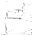
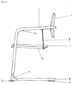
- a stand-up chair is shown in perspective, which has a chair frame with a lower frame part 4 and an upper frame part 3, a support surface in the form of a seat surface 2, a backrest 1 attached to the upper frame part 3, foot pieces 6 and plate-like feet 7.
- the lower frame part 4 has a substantially horizontally rearward foot section, under which the plate-like feet 7 are arranged and in the arcuate rear region a box-like carrier 11 is inserted. In the front area, the lower frame part 4 merges in one piece into two upwardly directed, straight and essentially parallel to each other upwardly directed sections 5.
- the upper frame part 3 has telescopically pushed over the upwardly directed sections 5, downward-pointing sections which run above the seat surface 2 as armrests and carry the backrest 1 in their likewise arcuate rear section.
- An actuating element 12 for triggering is on an armrest a traction device accommodated in the box-like carrier 11.
- a front area of the seat surface 2 is pivotally mounted on a cross strut 10 attached to the downwardly leading sections of the upper frame part 3, while a rear area of the seat surface 2 is mounted by means of lateral cables 9 and a transverse connecting part 8 held on them.
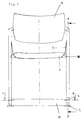
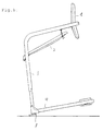
- FIGS. 2 and 3 The structure described can also be seen in FIGS. 2 and 3 in a side view and a front view, in particular from FIG. 2 the mounting of the feet 7 on an intermediate piece 13 can be seen more clearly.
- the structure described results in a stand-up chair in the form of a cantilever chair.
- FIG. 4 shows a partially sectioned section of the stand-up chair shown in FIGS. 1 to 3, a mechanism for a pivoting movement of the seat part 2 being illustrated.
- the rope 9 holding the rear region of the seat surface 2 is guided over a first and a second deflecting roller 14, 15 and is attached to a fastening point 16 in the upper end region of the upward section 5 of the lower frame part 4. If the upper frame part 3 is guided upwards relative to the lower frame part 4, the rear region of the seat part 2 is pivoted upwards as a result of the arrangement of the rope 9.
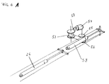
- 5 shows the guidance of a rope 24 in the cavity of the tubular lower frame part 4.
- 5A, 5B and 6 show, the cable 24 is guided out of the box-like carrier 11 via a deflection roller 23 into the foot section of the lower frame 4 and extends over a further roller 18 into the upward section 5 of the lower frame part 4 and is in this is guided downwards via an upper deflection roller 17 and attached to a coupling member 19 which is connected to the tubular, downwardly leading section of the upper frame part 3 by a slot 20 running in the longitudinal direction.
- the pulling device accommodated in the box-like carrier 11 has a storage element in the form of a tensioning unit or gas spring 26, to the lifting rod of which the cable 24 is connected in such a way that when the lifting rod is extended, the cable 24 is in the box-like carrier 11 is drawn in.
- a further cable 25 guided in the opposite tubular foot section and upward section of the lower frame part 4 is drawn into the box-like support 11 when the lifting rod is extended.
- the further cable 25 is guided over a deflection roller 21 arranged in the box-like carrier 11 and its end is attached to the end section of the lifting rod of the gas spring 26 in accordance with the cable 24.
- a further deflection roller 22 is provided for guiding the further rope 25 in the foot section of the lower frame part 4.
- the pulling device has two clamping units connected in parallel in the form of the gas spring 26 and an additional gas spring 58, which forms a further storage element.
- the additional gas spring 58 can be pretensioned by means of an electrically (or hydraulically) operated drive 54.
- a deflection unit for guiding tensioning cables with a type of cable winch is formed, for example, by means of a gear 57 and rollers 55, 56, 53.
- the additional gas spring 58 can be pretensioned at a point in time when the upper position of the support surface 2 is reached and this is relieved, so that the reduced force of the single-acting gas spring 26 is effective during the setting process.
- the additional gas spring 58 is switched on, so that the rising process is supported by both gas springs 26, 58. In this way, units with more than two gas springs can also be operated, wherein more than one additional gas spring can be provided.
- the actuating element 12 is actuated until the stand-up position is reached.
- Fig. 7 shows the stand-up chair described in the raised position, in which the seat 2 is tilted. 8 and 9 also show the stand-up chair in the raised position, the entire stand-up chair being inclined for movement on the feet 7, which, for. B. enable a rolling or sliding movement about a vertical axis.
- Fig. 10 shows another embodiment of the stand-up aid in the form of a stand-up chair, and also a cantilever chair.
- This chair also consists of a lower frame part 4, an upper frame part 3, feet 7, a support surface in the form of a seat surface 2 and a backrest 1.
- the front section of the seat surface 2 is supported on a support section with a first connecting and guide piece 31 a .
- the box-like carrier 30 is arranged under the seat 2, as shown in FIG. 11.
- 12 shows the adjustment mechanism of this exemplary embodiment with individual parts.
- 13 shows the guidance of a first rope 39 in the cavity of the frame formed from the lower and upper frame parts 4, 3 in detail.
- the first rope 39 runs according to a further rope 40 arranged on the other side, from a connection point at the end of a lifting rod of the tensioning unit 45 via a first or second roller 35, 36 via the first connecting and guide piece 31a or a further connecting piece. and guide pieces 32 via a slot 20 'into the cavity of the upward section 5 of the lower frame part 4, the first cable 39 being deflected upwards via a third roller 44 arranged laterally on the seat surface 2.
- An upper deflection element 17 ' is arranged in the cavity of the frame above the slot 20', via which the first cable 39 (and correspondingly also the further cable 40) is guided downwards to an anchoring element 42 and is fixed there by means of a clamp 43.
- 15A to 15D show various further exemplary embodiments for stand-up aids in which the mechanisms described can be used, namely a wheelchair, a height-adjustable standing aid, a stool and one Movement aid in a lowered and raised position in a suitable position.
- the respective force for raising and lowering can be adapted to the weight of the user by means of appropriate, optionally adjustable gas springs.
- the raised position can be set by means of an actuating element in accordance with the actuating element 12 of the exemplary embodiments described above.
- the actuator 12 is via a suitable connection, for. B. a connecting cable connected to the tension units.
- the additional gas spring 58 is preferably released from the drive 54 when the user is lowered. When lifting, it is possible to stop in the desired position using the actuating element.
Landscapes
- Health & Medical Sciences (AREA)
- Life Sciences & Earth Sciences (AREA)
- Animal Behavior & Ethology (AREA)
- General Health & Medical Sciences (AREA)
- Public Health (AREA)
- Veterinary Medicine (AREA)
- Accommodation For Nursing Or Treatment Tables (AREA)
- Invalid Beds And Related Equipment (AREA)
Applications Claiming Priority (2)
| Application Number | Priority Date | Filing Date | Title |
|---|---|---|---|
| DE19620802 | 1996-05-23 | ||
| DE19620802 | 1996-05-23 |
Publications (2)
| Publication Number | Publication Date |
|---|---|
| EP0808621A2 true EP0808621A2 (fr) | 1997-11-26 |
| EP0808621A3 EP0808621A3 (fr) | 1998-01-07 |
Family
ID=7795135
Family Applications (1)
| Application Number | Title | Priority Date | Filing Date |
|---|---|---|---|
| EP97108303A Withdrawn EP0808621A3 (fr) | 1996-05-23 | 1997-05-22 | Aide de levage |
Country Status (1)
| Country | Link |
|---|---|
| EP (1) | EP0808621A3 (fr) |
Cited By (2)
| Publication number | Priority date | Publication date | Assignee | Title |
|---|---|---|---|---|
| WO2019229730A1 (fr) * | 2018-06-01 | 2019-12-05 | Jenkins Joyce J | Plateforme de levage d'un individu depuis une position de chute |
| CN110801370A (zh) * | 2019-11-22 | 2020-02-18 | 张卫中 | 辅助站立机及侧面承重升降立柱 |
Family Cites Families (2)
| Publication number | Priority date | Publication date | Assignee | Title |
|---|---|---|---|---|
| GB531184A (en) * | 1939-06-28 | 1940-12-31 | Robert Alexander Douglas Flemi | Improvements in or relating to invalid chairs and the like |
| US4872223A (en) * | 1985-09-26 | 1989-10-10 | Baird Lincoln F | Orthopedic chair |
-
1997
- 1997-05-22 EP EP97108303A patent/EP0808621A3/fr not_active Withdrawn
Cited By (2)
| Publication number | Priority date | Publication date | Assignee | Title |
|---|---|---|---|---|
| WO2019229730A1 (fr) * | 2018-06-01 | 2019-12-05 | Jenkins Joyce J | Plateforme de levage d'un individu depuis une position de chute |
| CN110801370A (zh) * | 2019-11-22 | 2020-02-18 | 张卫中 | 辅助站立机及侧面承重升降立柱 |
Also Published As
| Publication number | Publication date |
|---|---|
| EP0808621A3 (fr) | 1998-01-07 |
Similar Documents
| Publication | Publication Date | Title |
|---|---|---|
| DE3337536C2 (fr) | ||
| DE2328399C3 (de) | Lehnstuhl | |
| DE7711866U1 (de) | Hubstuhl | |
| DE2618943A1 (de) | Lehnstuhl mit motorisch betriebener kipplehnen- und sitzhebemechanik | |
| DE2910574A1 (de) | Gynaekologischer stuhl | |
| DE3126003A1 (de) | Verstellbarer sessel | |
| EP0902677B1 (fr) | Fauteuil de dentiste avce dispositif de reglage du siege et du dossier a accouplement force | |
| EP0193730A2 (fr) | Accessoire pour baignoire | |
| EP0405542A2 (fr) | Chaise roulante | |
| WO2023161842A1 (fr) | Accessoire fonctionnel motorisé pour sommier de lit à sommier tapissier ou de lit plateforme, ou pour sommier à lattes | |
| EP1280494B1 (fr) | Leve-personne pour baignoire | |
| EP0808621A2 (fr) | Aide de levage | |
| EP2679211B1 (fr) | Siège doté d'un dispositif d'aide pour se lever | |
| DE19732950C2 (de) | Rollstuhlschaukel | |
| DE19702171A1 (de) | Sitz, Sitzauflage, Sitzgestell oder entsprechende Vorrichtung mit Wirbelsäulenentlastung | |
| DE2629475A1 (de) | Kipplehnstuhl | |
| DE19532671C2 (de) | Verstellbare Liege | |
| DE19649576A1 (de) | Regulierbare Abstützvorrichtung | |
| DE4430303A1 (de) | Sitzmöbel mit ausklappbarer Beinstütze | |
| AT408309B (de) | Sitz-liege-möbel | |
| DE9200347U1 (de) | Sessel-Liege | |
| DE10058546A1 (de) | Verwandlungsmöbel | |
| EP0819416A2 (fr) | Dispositif pour abaisser et lever une personne handicapée | |
| EP1118291A2 (fr) | Meuble pour s'asseoir | |
| AT400505B (de) | Möbel mit einer rückenlehne |
Legal Events
| Date | Code | Title | Description |
|---|---|---|---|
| PUAI | Public reference made under article 153(3) epc to a published international application that has entered the european phase |
Free format text: ORIGINAL CODE: 0009012 |
|
| PUAL | Search report despatched |
Free format text: ORIGINAL CODE: 0009013 |
|
| AK | Designated contracting states |
Kind code of ref document: A2 Designated state(s): AT DE ES FR IT |
|
| AK | Designated contracting states |
Kind code of ref document: A3 Designated state(s): AT DE ES FR IT |
|
| 17P | Request for examination filed |
Effective date: 19980424 |
|
| GRAG | Despatch of communication of intention to grant |
Free format text: ORIGINAL CODE: EPIDOS AGRA |
|
| 17Q | First examination report despatched |
Effective date: 20010529 |
|
| GRAG | Despatch of communication of intention to grant |
Free format text: ORIGINAL CODE: EPIDOS AGRA |
|
| GRAH | Despatch of communication of intention to grant a patent |
Free format text: ORIGINAL CODE: EPIDOS IGRA |
|
| GRAH | Despatch of communication of intention to grant a patent |
Free format text: ORIGINAL CODE: EPIDOS IGRA |
|
| STAA | Information on the status of an ep patent application or granted ep patent |
Free format text: STATUS: THE APPLICATION IS DEEMED TO BE WITHDRAWN |
|
| 18D | Application deemed to be withdrawn |
Effective date: 20021203 |