EP0808946B1 - Fixation de rail - Google Patents
Fixation de rail Download PDFInfo
- Publication number
- EP0808946B1 EP0808946B1 EP96108053A EP96108053A EP0808946B1 EP 0808946 B1 EP0808946 B1 EP 0808946B1 EP 96108053 A EP96108053 A EP 96108053A EP 96108053 A EP96108053 A EP 96108053A EP 0808946 B1 EP0808946 B1 EP 0808946B1
- Authority
- EP
- European Patent Office
- Prior art keywords
- fact
- rail
- rail fastening
- anchor element
- fastening according
- Prior art date
- Legal status (The legal status is an assumption and is not a legal conclusion. Google has not performed a legal analysis and makes no representation as to the accuracy of the status listed.)
- Expired - Lifetime
Links
Images


Classifications
-
- E—FIXED CONSTRUCTIONS
- E01—CONSTRUCTION OF ROADS, RAILWAYS, OR BRIDGES
- E01B—PERMANENT WAY; PERMANENT-WAY TOOLS; MACHINES FOR MAKING RAILWAYS OF ALL KINDS
- E01B9/00—Fastening rails on sleepers, or the like
- E01B9/02—Fastening rails, tie-plates, or chairs directly on sleepers or foundations; Means therefor
- E01B9/28—Fastening on wooden or concrete sleepers or on masonry with clamp members
- E01B9/30—Fastening on wooden or concrete sleepers or on masonry with clamp members by resilient steel clips
- E01B9/303—Fastening on wooden or concrete sleepers or on masonry with clamp members by resilient steel clips the clip being a shaped bar
-
- E—FIXED CONSTRUCTIONS
- E01—CONSTRUCTION OF ROADS, RAILWAYS, OR BRIDGES
- E01B—PERMANENT WAY; PERMANENT-WAY TOOLS; MACHINES FOR MAKING RAILWAYS OF ALL KINDS
- E01B9/00—Fastening rails on sleepers, or the like
- E01B9/02—Fastening rails, tie-plates, or chairs directly on sleepers or foundations; Means therefor
- E01B9/04—Fastening on wooden or concrete sleepers or on masonry without clamp members
- E01B9/10—Screws or bolts for sleepers
Definitions
- the present invention relates to a Concrete sleepers or the like pre-assembled Rail fastening, which is on both sides of the rail on the Rail attachment point is arranged and each an elastic clamp spring and an angular one Has guide plate, the guide plate with one side on the rail foot and on that of the rail opposite side with an inclined surface on one corresponding support surface of a recess Concrete sleeper or the like is applied and the Guide plate and the clamping spring by means of a in the Anchored concrete sleeper or the like Fasteners held in their pre-assembly position be and the clamping spring in the final assembly position presses the rail foot.
- Such a rail attachment is from the DE 39 18 091 A1 known.
- the tension clamps from the pre-assembly position as far as Moved towards the rail until it was on the Side facing away from the rail in a in the angle guide plate engage trained guide groove and press their free ends onto the rail foot.
- the position is then dismantled by the Threshold screws using a torque wrench be tightened until a desired clamping force is reached, the middle part of the tension clamp in one comes to a small distance above the rail foot.
- This known rail fastening is characterized by a easy pre-assembly as well as a simple transition from the Pre-assembly in the final assembly position after inserting the Rail off.
- the angle guide plates sure that horizontal forces are directly on the concrete sleepers are transmitted and thus only pure tensile forces on the Threshold screws act so that they do not can solve automatically.
- Screwless rail fastening systems require special Anchoring in the sleepers.
- Systems are known where springs, for example, parallel to the rail or be threaded perpendicular to the rail. Also exist in the prior art systems in which a spring end in one opening is inserted, after which the second Spring end by lever into a second half-open bracket use.
- EP 0 373 099 A1 describes one on concrete sleepers pre-assembled rail fastener known, the one elastic clamping spring and an angular guide plate having.
- the clamping spring is in one piece with it trained fasteners in the form of a Anchor element provided in a concrete sleeper cast sleeve is anchored. For this is the sleeve at one end with a radial extension provided, in the radial at the end of the anchor element protruding paragraph can be screwed.
- the tension the clamping spring takes place in that this with a cooperates on the guide plate arranged ramp.
- the guide plate is relatively flat. Accordingly, it is due to its facing away from the rail Side on a relatively small, essentially vertical support surface of a recess in the concrete sleeper on. This guide plate can therefore only be used relatively Introduce low horizontal forces into the concrete sleeper.
- the present invention is based on the object a rail fastening of the type mentioned above improve that besides the benefits of screwed Rail fastening systems, such as the direct derivation of Horizontal forces in the concrete body, an even faster and easier rail mounting.
- the fastener is an anchor element attached to one within the Threshold mounted cam plate attacks when Twisting the anchor element tensioning the clamping spring causes.
- the solution according to the invention represents a kind Quick release represents an almost foolproof Rail assembly guaranteed. By maintaining the for taken known angular guide plate this in turn ensures that only tensile forces, however, no shear forces act on the anchor element.
- Clamping springs can e.g. Tension clamps, so-called fast clips or the like are used.
- a preferred embodiment of the invention Rail fastening is characterized in that the Cam is stepped and at least has a ramp-shaped section over which the Clamping spring is tensioned when the anchor element is rotated.
- the anchor element is preferably lockable. to The anchor element can be locked in the cam disc one or more rest stages are formed, which different degrees of tension assigned to the clamping spring are.
- the cam disc a first rising has ramp-shaped section, which in a first Resting stage passes, to which an in turn increases second ramp-shaped section that connects into a second rest stage passes, the first rest stage one Pre-assembly position and the second locking step one Final assembly position corresponds.
- the ramped sections can be different Have slopes, preferably the slope of the first section is larger than that of the second Section. In this way, the torque increase be reduced when tensioning the clamping spring, so that turning the anchor element into the final assembly position is relieved accordingly.
- Anchor claws should be formed.
- the anchor element To attach a wrench or another suitable tool, the anchor element have standardized railroad screw head. Alternatively, it can also be useful if the Head of the anchor element is designed so that only a special one, but not a commercially available one Wrench can be attached. In this way unauthorized persons prevent the anchoring from being loosened or at least difficult. For example, that Anchoring element an internal key approach have and / or with an opening or holding part be provided for the attachment of a crossbar.
- the cam in one in the Concrete sleeper arranged housing is held that preferably consists of plastic. That way it is possible to put the cam with the housing directly in to integrate the concrete sleeper in its manufacture.
- the housing serves as a placeholder and the electrical track insulation, provided it is made of plastic or another electrically insulating material is made.
- the anchor element can also be in a sleeve made of plastic or another electrical insulating material.
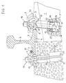
- 1 and 2 is the rail fastening according to the invention on the left half of the picture in the Final assembly position and on the right half of the picture in the Pre-assembled position shown, namely in Fig. 1 in a central longitudinal section through a concrete sleeper 1 and in Fig. 2 in a plan view, but the Concrete sleeper omitted and the rail 2 outside the Epsilon-shaped clamping springs 3 is cut off.
- the left side shows the track exterior and the right side the track interior, with the rail 2 in the track exterior in the assembled state and in the track interior in pre-assembled state is shown.
- the rail 2 the here using the example of the well-known UIC 60 rail profile is shown using a vibration damping Liner 4 on the concrete sleeper 1 between two angular guide plates 5, the Rail axis in a known manner in a fixed Ratio of e.g. 1:40 compared to the vertical to Track interior is inclined.
- the angular ones Guide plates 5 each have a longitudinal rib 6, with which they rest on the rail foot 7.
- the guide plates 5 each have an inclined surface 8 with which they the side facing away from the rail 2 on one corresponding support surface 9 of a recess 10 in the Apply concrete sleeper 1.
- Anchor elements 15, each having a clamping spring 3 holding head 16 and an angled end 17th have, which on a within the concrete sleeper 1st stored cam 18 attacks.
- the cams 18 are each inserted in a plastic housing 19, with which they are used in the manufacture of the concrete sleeper 1 poured into the concrete mass.
- the housing 19 can be aligned obliquely so that the central axis of the anchor element 15 used therein Intersects the rail axis below the rail (see Fig. 1).
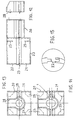
- the housing 19 is composed of two parts 20, 21 together, with a slight press fit through a tongue and groove connection 22 can be positively connected to one another are (see Figs. 14 and 15).
- the housing 19 forms a chamber-like section 23, which has a rectangular cross section.
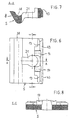
- the Cam 18 is accordingly with an im provided substantially rectangular shaped paragraph 24, such as can be seen particularly well in FIG. 9.
- Paragraph 24 is in the upper area of the chamber-like Housing section 23 by four lying in one plane Support ribs 25 held so that the cam 18 in the axial direction of the anchor element 15 is fixed.
- On the chamber-shaped section 23 closes in the direction a tubular housing section of the threshold top 26 with a keyhole-shaped cross section one round and one essentially rectangular Has partial area 27 or 28.
- the rectangular one Partial area 28 is bevelled on the upper side, so that the Housing 19 in concrete just below each Recess 10 arranged for the angle guide plate 5 can be.
- the housing 19 is on the underside an opening 29 provided with a recess 30 in the underside of the threshold meets (see FIG. 1).
- the anchor element 15 can with its angled End section 17 from the top of the concrete sleeper 1 through an elongated hole-like opening 31 within the Guide plate 5 through the channel-shaped Section 26 in the chamber-like housing section 23 be introduced.
- the Cam 18 on a U-shaped opening 32 with the channel-shaped housing section 26 meets, so that the angled end 17 of the anchor element 15th easily pass cam 18 and on it can attack on the underside.
- the cam disc 18 has a first ramp-shaped Section 33 with a relatively large slope on the passes into a first trough-shaped locking step 34. On this first locking step 34 closes a second ramped section 35, which is a smaller Has slope and into a second trough-shaped Locking step 36 passes (see. Fig. 9 to 11).
- the first Locking step 34 serves to lock the anchor element 15 in the pre-assembly position.
- the epsilon-shaped Clamping springs 3 After the rail 2 between the angle guide plates 5 using the liner 4 on the Concrete sleeper 1 is placed, the epsilon-shaped Clamping springs 3 from the pre-assembly position in Pushed towards the rail 2 so that their free Press leg ends 12 onto the rail foot 7 and the leg 37 facing away from rail 2 in the longitudinal groove 38 engage the guide plate 5.
- the angled end section 17 becomes the final assembly position of the anchor element 15 then from the first latching step 34 via the second ramp-shaped section 35 into the second locking step 36 rotated and finally there again locked.
- the shaft of the anchor element 15 looping middle part 39 of the clamping spring 3 comes at a slight distance above the rail foot 7 lie. In this way, the rail 1 with a certain tension force pressed onto the concrete sleeper 1 (see right and left half of Fig. 1).
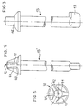
- the rod-shaped anchor element 15 can be released instead a railroad sleeper screw head 16 preferably a specially designed head 40 exhibit.
- 4 and 5 is an example of one such special anchor element 15 'shown.
- the head 40 this anchor element 15 ' has three at about 120 ° offset polygonal attachment surfaces 41 for one appropriately trained special keys.
- At the The top of the head 40 is also a bore 42 arranged in the one on the special key (not shown) provided guide pin can be inserted.
Landscapes
- Engineering & Computer Science (AREA)
- Mechanical Engineering (AREA)
- Architecture (AREA)
- Civil Engineering (AREA)
- Structural Engineering (AREA)
- Railway Tracks (AREA)
- Connection Of Plates (AREA)
- Fuel-Injection Apparatus (AREA)
- Clamps And Clips (AREA)
Claims (18)
- Fixation de rail pouvant être prémontée sur des traverses en béton (1) ou similaires, disposée des deux côtés du rail (2) à l'emplacement de fixation du rail et présentant respectivement un ressort de serrage élastique (3) et une plaque de guidage pliée en angle (5), dans laquelle la plaque de guidage (5) est en appui d'un côté contre le patin du rail (7) et, du côté opposé au rail (2), par l'intermédiaire d'une surface oblique (8), sur une surface d'appui correspondante d'un évidement de la traverse en béton (1) ou similaire, et dans laquelle la plaque de guidage (5) et le ressort de serrage (3) sont maintenus dans leur position de prémontage au moyen d'un élément de fixation ancré dans la traverse en béton (1) ou similaire, et le ressort de serrage (3), dans la position de montage final, appuie sur le patin du rail (7), caractérisée en ce que l'élément de fixation est un élément d'ancrage (15) qui est en prise avec une came (18), noyée dans la traverse (1), qui a pour effet de tendre le ressort de serrage (3) lorsqu'on applique une torsion à l'élément d'ancrage (15).
- Fixation de rail selon la revendication 1, caractérisée en ce que la came (18) a une forme étagée et présente au moins une partie en forme de rampe (33 ; 35).
- Fixation de rail selon la revendication 1 ou la revendication 2, caractérisée en ce que la came (18) présente un ou plusieurs paliers d'arrêt (34 ; 36).
- Fixation de rail selon la revendication 2 ou la revendication 3, caractérisée en ce que la came (18) présente une première partie en forme de rampe montante (33) terminée par un premier palier d'arrêt (34) lui-même suivi d'une deuxième partie en forme de rampe également montante (35) terminée par un deuxième palier d'arrêt (36), le premier palier d'arrêt (34) correspondant à une position de prémontage et le deuxième palier d'arrêt (35) à une position de montage final.
- Fixation de rail selon la revendication 4, caractérisée en ce que les parties en forme de rampe (33 ; 35) présentent des pentes différentes.
- Fixation de rail selon l'une des revendications précédentes, caractérisée en ce que l'élément d'ancrage (15) présente une partie d'extrémité repliée (17) en prise avec la came (18).
- Fixation de rail selon l'une des revendications précédentes, caractérisée en ce que l'élément d'ancrage (15) présente une tête de boulon normalisée (16).
- Fixation de rail selon l'une des revendications 1 à 6, caractérisée en ce que l'élément d'ancrage (15) présente une tête (40) qui peut être entraínée de manière positive par une clé emmanchée spéciale mais pas par une clé disponible dans le commerce, de façon à empêcher un desserrage de l'élément d'ancrage (15) par des personnes non autorisées.
- Fixation de rail selon l'une des revendications précédentes, caractérisée en ce que la came (18) est maintenue dans un boítier (19) agencé dans la traverse en béton (1).
- Fixation de rail selon la revendication 9, caractérisée en ce que le boítier (19) est en matière plastique.
- Fixation de rail selon l'une des revendications précédentes, caractérisée en ce que l'élément d'ancrage (15) est muni d'une enveloppe en matière plastique.
- Fixation de rail selon l'une des revendications précédentes, caractérisée en ce que l'élément d'ancrage (15) est disposé dans un manchon en matière plastique ou un autre matériau électriquement isolant.
- Fixation de rail selon l'une des revendications précédentes, caractérisée en ce que le ressort de serrage (3) peut être déplacé de la position de prémontage à la position de montage final.
- Fixation de rail selon l'une des revendications précédentes, caractérisée en ce que la plaque de guidage (5) présente une gorge de guidage (38) dans laquelle le ressort de serrage (3) vient en prise dans la position de montage final.
- Fixation de rail selon la revendication 14, caractérisée en ce que la plaque de guidage (5) présente une ouverture oblongue (31) à travers laquelle la partie d'extrémité repliée (17) de l'élément d'ancrage (15) peut être introduite.
- Fixation de rail selon la revendication 14 ou la revendication 15, caractérisée en ce que le ressort de serrage (3) est une bride de serrage recourbée ayant une forme telle que ses bras intérieurs (11) sont enroulés autour de l'élément d'ancrage (15) et sont recouverts par l'élément d'ancrage (15).
- Fixation de rail selon la revendication 16, caractérisée en ce que la plaque de guidage (5) est munie de butées (13) contre lesquelles les extrémités libres (12) de la bride de serrage (3) sont en appui dans la position de prémontage.
- Fixation de rail selon la revendication 16, caractérisée en ce que le ressort de serrage (3) est une bride de serrage en forme d'epsilon.
Priority Applications (3)
| Application Number | Priority Date | Filing Date | Title |
|---|---|---|---|
| EP96108053A EP0808946B1 (fr) | 1996-05-21 | 1996-05-21 | Fixation de rail |
| DE59608964T DE59608964D1 (de) | 1996-05-21 | 1996-05-21 | Schienenbefestigung |
| AT96108053T ATE215150T1 (de) | 1996-05-21 | 1996-05-21 | Schienenbefestigung |
Applications Claiming Priority (1)
| Application Number | Priority Date | Filing Date | Title |
|---|---|---|---|
| EP96108053A EP0808946B1 (fr) | 1996-05-21 | 1996-05-21 | Fixation de rail |
Publications (2)
| Publication Number | Publication Date |
|---|---|
| EP0808946A1 EP0808946A1 (fr) | 1997-11-26 |
| EP0808946B1 true EP0808946B1 (fr) | 2002-03-27 |
Family
ID=8222803
Family Applications (1)
| Application Number | Title | Priority Date | Filing Date |
|---|---|---|---|
| EP96108053A Expired - Lifetime EP0808946B1 (fr) | 1996-05-21 | 1996-05-21 | Fixation de rail |
Country Status (3)
| Country | Link |
|---|---|
| EP (1) | EP0808946B1 (fr) |
| AT (1) | ATE215150T1 (fr) |
| DE (1) | DE59608964D1 (fr) |
Families Citing this family (10)
| Publication number | Priority date | Publication date | Assignee | Title |
|---|---|---|---|---|
| DE19807627A1 (de) * | 1998-02-23 | 1999-08-26 | Ortwein | Unterbau für ein aus Schienen gebildetes Gleis für Schienenfahrzeuge |
| RU2300600C2 (ru) * | 2005-01-17 | 2007-06-10 | Общество с ограниченной ответственностью Совместное российско-американское предприятие "Технология XXI века" | Рельсовое скрепление |
| DE102005058465A1 (de) * | 2005-12-07 | 2007-06-28 | Db Netz Ag | Befestigungsmittel zur Befestigung von Bahnschienen auf Gleisschwellen oder Gleisfahrwegen |
| ITTV20060051A1 (it) | 2006-03-30 | 2007-09-30 | Emmetechnic Srl | Elemento elastico |
| ES2283235B1 (es) | 2007-04-04 | 2009-03-01 | Mondragon Soluciones, S.L.U. | Vaina para sujeciones de railes ferroviarios, procedimiento para reemplazar dicha vaina en una traviesa y utiles para ejecutar dicho procedimiento. |
| PT2410090E (pt) * | 2010-07-19 | 2015-07-06 | Schwihag Ag | Sistema de fixação de carris |
| DE102010060745A1 (de) | 2010-11-23 | 2012-05-24 | Vossloh-Werke Gmbh | Führungsplatte zum seitlichen Führen einer Schiene und System zum Befestigen einer Schiene |
| DE102012003989B4 (de) | 2012-02-28 | 2022-06-09 | Elisabeth Ortwein | Unterbau für ein aus Schienen gebildetes Gleis für Schienenfahrzeuge |
| CN109910165A (zh) * | 2019-03-21 | 2019-06-21 | 北京好运达智创科技有限公司 | 用于安装高铁轨枕预埋套管的涨紧式定位轴 |
| CN110359325A (zh) * | 2019-08-02 | 2019-10-22 | 太仓中博铁路紧固件有限公司 | 一种钢轨的扣件组装结构及对应的钢轨安装方法 |
Family Cites Families (3)
| Publication number | Priority date | Publication date | Assignee | Title |
|---|---|---|---|---|
| DE8505959U1 (de) * | 1985-03-01 | 1985-06-27 | Vossloh-Werke Gmbh, 5980 Werdohl | Bausatz zur Befestigung von Schienen |
| FR2639971B1 (fr) * | 1988-12-02 | 1991-02-08 | Vape Sa Ets | Bride de fixation rapide d'un rail de chemin de fer et traverse munie d'une telle bride |
| DE8906790U1 (de) * | 1989-06-02 | 1989-08-31 | Vossloh-Werke GmbH, 58791 Werdohl | Schienenbefestigung auf Betonschwellen od.dgl. mittels elastischer Spannklemmen |
-
1996
- 1996-05-21 EP EP96108053A patent/EP0808946B1/fr not_active Expired - Lifetime
- 1996-05-21 AT AT96108053T patent/ATE215150T1/de not_active IP Right Cessation
- 1996-05-21 DE DE59608964T patent/DE59608964D1/de not_active Expired - Lifetime
Also Published As
| Publication number | Publication date |
|---|---|
| EP0808946A1 (fr) | 1997-11-26 |
| DE59608964D1 (de) | 2002-05-02 |
| ATE215150T1 (de) | 2002-04-15 |
Similar Documents
| Publication | Publication Date | Title |
|---|---|---|
| DE102008003744B3 (de) | Abstützung für ein System zum Befestigen einer Schiene und System zum Befestigen einer Schiene | |
| DE2314168C3 (de) | Einstückiges Ankerelement für Stehbolzen | |
| DD291593A5 (de) | Schienenbefestigung auf betonschwellen od. dgl. mittels elastischer spannklemmen | |
| DE202007018602U1 (de) | System zum Befestigen einer Schiene | |
| EP0808946B1 (fr) | Fixation de rail | |
| EP1899613B1 (fr) | Vis d'ancrage | |
| EP0194550B1 (fr) | Attache de fixation et dispositif de fixation pour rails de chemin de fer | |
| DE102005000129A1 (de) | Befestigungsvorrichtung für die Befestigung von Solarpaneelen an einer Montageschiene | |
| EP1222406B1 (fr) | Element de retenue pour vis a tete | |
| EP0794289A1 (fr) | Fixation élastique de rail | |
| DE19642971C2 (de) | Federnde Schienenbefestigung | |
| DE2916003A1 (de) | Befestigungsvorrichtung, insbesondere fuer die verbindung von zwei bauteilen von bauwerken | |
| EP2609255B1 (fr) | Système de fixation de rail | |
| EP2039834A1 (fr) | Elément de fixation destiné à raccorder des objets urbains, comme des poteaux avec et sans éclairage, du mobilier urbain, des panneaux de signalisation, du mobilier de terrain de jeux pour enfants et analogues, à l'aide d'un manchon d'ancrage installé dans le sol | |
| DE19604174A1 (de) | Verfahren und Vorrichtung zur Befestigung von Geländerpfosten an einer Betonplatte | |
| DE3620573A1 (de) | Vorrichtung zum befestigen eines gegenstandes an einer wand oder dgl. | |
| EP4581210B1 (fr) | Ressort tendeur permettant de retenir un élément de voie ferrée | |
| DE4303731A1 (de) | Montageelement und Verfahren zu seiner Befestigung an Profilträgern | |
| DE3509473C2 (fr) | ||
| EP1860334A1 (fr) | Dispositif de ressorts conique et ensemble de raccordement électrique comprenant un tel dispositif | |
| EP2155998B1 (fr) | Ensemble tige de crémone et procédé de montage d'un ensemble tige de crémone | |
| DE10156222C1 (de) | Vorrichtung zur Verankerung von Hohlprofilelementen | |
| DE4418710C2 (de) | Verbindung für mit Zugankern versehene Hausschornsteinelemente | |
| EP1141486A1 (fr) | Vis d'ancrage pour traverse et analogue | |
| EP1306111A1 (fr) | Fixation pour poteaux dans la terre, spécialement pour piquets de slalom |
Legal Events
| Date | Code | Title | Description |
|---|---|---|---|
| PUAI | Public reference made under article 153(3) epc to a published international application that has entered the european phase |
Free format text: ORIGINAL CODE: 0009012 |
|
| AK | Designated contracting states |
Kind code of ref document: A1 Designated state(s): AT BE CH DE DK ES FI FR GB GR IE IT LI LU MC NL PT SE |
|
| 17P | Request for examination filed |
Effective date: 19980108 |
|
| 17Q | First examination report despatched |
Effective date: 20000217 |
|
| GRAG | Despatch of communication of intention to grant |
Free format text: ORIGINAL CODE: EPIDOS AGRA |
|
| GRAG | Despatch of communication of intention to grant |
Free format text: ORIGINAL CODE: EPIDOS AGRA |
|
| GRAH | Despatch of communication of intention to grant a patent |
Free format text: ORIGINAL CODE: EPIDOS IGRA |
|
| GRAH | Despatch of communication of intention to grant a patent |
Free format text: ORIGINAL CODE: EPIDOS IGRA |
|
| REG | Reference to a national code |
Ref country code: GB Ref legal event code: IF02 |
|
| GRAA | (expected) grant |
Free format text: ORIGINAL CODE: 0009210 |
|
| AK | Designated contracting states |
Kind code of ref document: B1 Designated state(s): AT BE CH DE DK ES FI FR GB GR IE IT LI LU MC NL PT SE |
|
| PG25 | Lapsed in a contracting state [announced via postgrant information from national office to epo] |
Ref country code: NL Free format text: LAPSE BECAUSE OF FAILURE TO SUBMIT A TRANSLATION OF THE DESCRIPTION OR TO PAY THE FEE WITHIN THE PRESCRIBED TIME-LIMIT Effective date: 20020327 Ref country code: IT Free format text: LAPSE BECAUSE OF FAILURE TO SUBMIT A TRANSLATION OF THE DESCRIPTION OR TO PAY THE FEE WITHIN THE PRE;WARNING: LAPSES OF ITALIAN PATENTS WITH EFFECTIVE DATE BEFORE 2007 MAY HAVE OCCURRED AT ANY TIME BEFORE 2007. THE CORRECT EFFECTIVE DATE MAY BE DIFFERENT FROM THE ONE RECORDED.SCRIBED TIME-LIMIT Effective date: 20020327 Ref country code: IE Free format text: LAPSE BECAUSE OF FAILURE TO SUBMIT A TRANSLATION OF THE DESCRIPTION OR TO PAY THE FEE WITHIN THE PRESCRIBED TIME-LIMIT Effective date: 20020327 Ref country code: GR Free format text: LAPSE BECAUSE OF FAILURE TO SUBMIT A TRANSLATION OF THE DESCRIPTION OR TO PAY THE FEE WITHIN THE PRESCRIBED TIME-LIMIT Effective date: 20020327 Ref country code: GB Free format text: LAPSE BECAUSE OF FAILURE TO SUBMIT A TRANSLATION OF THE DESCRIPTION OR TO PAY THE FEE WITHIN THE PRESCRIBED TIME-LIMIT Effective date: 20020327 Ref country code: FR Free format text: LAPSE BECAUSE OF FAILURE TO SUBMIT A TRANSLATION OF THE DESCRIPTION OR TO PAY THE FEE WITHIN THE PRESCRIBED TIME-LIMIT Effective date: 20020327 Ref country code: FI Free format text: LAPSE BECAUSE OF FAILURE TO SUBMIT A TRANSLATION OF THE DESCRIPTION OR TO PAY THE FEE WITHIN THE PRESCRIBED TIME-LIMIT Effective date: 20020327 |
|
| REF | Corresponds to: |
Ref document number: 215150 Country of ref document: AT Date of ref document: 20020415 Kind code of ref document: T |
|
| REG | Reference to a national code |
Ref country code: CH Ref legal event code: EP |
|
| REF | Corresponds to: |
Ref document number: 59608964 Country of ref document: DE Date of ref document: 20020502 |
|
| REG | Reference to a national code |
Ref country code: IE Ref legal event code: FG4D Free format text: GERMAN |
|
| PG25 | Lapsed in a contracting state [announced via postgrant information from national office to epo] |
Ref country code: MC Free format text: LAPSE BECAUSE OF NON-PAYMENT OF DUE FEES Effective date: 20020521 Ref country code: LU Free format text: LAPSE BECAUSE OF NON-PAYMENT OF DUE FEES Effective date: 20020521 Ref country code: AT Free format text: LAPSE BECAUSE OF NON-PAYMENT OF DUE FEES Effective date: 20020521 |
|
| PG25 | Lapsed in a contracting state [announced via postgrant information from national office to epo] |
Ref country code: LI Free format text: LAPSE BECAUSE OF NON-PAYMENT OF DUE FEES Effective date: 20020531 Ref country code: CH Free format text: LAPSE BECAUSE OF NON-PAYMENT OF DUE FEES Effective date: 20020531 Ref country code: BE Free format text: LAPSE BECAUSE OF NON-PAYMENT OF DUE FEES Effective date: 20020531 |
|
| PG25 | Lapsed in a contracting state [announced via postgrant information from national office to epo] |
Ref country code: SE Free format text: LAPSE BECAUSE OF FAILURE TO SUBMIT A TRANSLATION OF THE DESCRIPTION OR TO PAY THE FEE WITHIN THE PRESCRIBED TIME-LIMIT Effective date: 20020627 Ref country code: PT Free format text: LAPSE BECAUSE OF FAILURE TO SUBMIT A TRANSLATION OF THE DESCRIPTION OR TO PAY THE FEE WITHIN THE PRESCRIBED TIME-LIMIT Effective date: 20020627 Ref country code: DK Free format text: LAPSE BECAUSE OF FAILURE TO SUBMIT A TRANSLATION OF THE DESCRIPTION OR TO PAY THE FEE WITHIN THE PRESCRIBED TIME-LIMIT Effective date: 20020627 |
|
| NLV1 | Nl: lapsed or annulled due to failure to fulfill the requirements of art. 29p and 29m of the patents act | ||
| GBV | Gb: ep patent (uk) treated as always having been void in accordance with gb section 77(7)/1977 [no translation filed] |
Effective date: 20020327 |
|
| PG25 | Lapsed in a contracting state [announced via postgrant information from national office to epo] |
Ref country code: ES Free format text: LAPSE BECAUSE OF FAILURE TO SUBMIT A TRANSLATION OF THE DESCRIPTION OR TO PAY THE FEE WITHIN THE PRESCRIBED TIME-LIMIT Effective date: 20020925 |
|
| REG | Reference to a national code |
Ref country code: IE Ref legal event code: FD4D |
|
| EN | Fr: translation not filed | ||
| REG | Reference to a national code |
Ref country code: CH Ref legal event code: PL |
|
| PLBE | No opposition filed within time limit |
Free format text: ORIGINAL CODE: 0009261 |
|
| STAA | Information on the status of an ep patent application or granted ep patent |
Free format text: STATUS: NO OPPOSITION FILED WITHIN TIME LIMIT |
|
| 26N | No opposition filed |
Effective date: 20021230 |
|
| PGFP | Annual fee paid to national office [announced via postgrant information from national office to epo] |
Ref country code: DE Payment date: 20150520 Year of fee payment: 20 |
|
| REG | Reference to a national code |
Ref country code: DE Ref legal event code: R071 Ref document number: 59608964 Country of ref document: DE |