EP0808962A1 - Faux plancher - Google Patents
Faux plancher Download PDFInfo
- Publication number
- EP0808962A1 EP0808962A1 EP97108191A EP97108191A EP0808962A1 EP 0808962 A1 EP0808962 A1 EP 0808962A1 EP 97108191 A EP97108191 A EP 97108191A EP 97108191 A EP97108191 A EP 97108191A EP 0808962 A1 EP0808962 A1 EP 0808962A1
- Authority
- EP
- European Patent Office
- Prior art keywords
- installation floor
- floor according
- support
- installation
- screw
- Prior art date
- Legal status (The legal status is an assumption and is not a legal conclusion. Google has not performed a legal analysis and makes no representation as to the accuracy of the status listed.)
- Withdrawn
Links
- 238000009434 installation Methods 0.000 claims description 70
- 239000000463 material Substances 0.000 claims description 16
- 229910052500 inorganic mineral Inorganic materials 0.000 claims description 13
- 239000011707 mineral Substances 0.000 claims description 13
- 230000000295 complement effect Effects 0.000 claims description 9
- 238000004382 potting Methods 0.000 claims 1
- 230000000284 resting effect Effects 0.000 claims 1
- OSGAYBCDTDRGGQ-UHFFFAOYSA-L calcium sulfate Chemical compound [Ca+2].[O-]S([O-])(=O)=O OSGAYBCDTDRGGQ-UHFFFAOYSA-L 0.000 description 14
- 210000001503 joint Anatomy 0.000 description 7
- 239000004570 mortar (masonry) Substances 0.000 description 7
- 239000004566 building material Substances 0.000 description 4
- 229910052602 gypsum Inorganic materials 0.000 description 3
- 239000010440 gypsum Substances 0.000 description 3
- 239000004033 plastic Substances 0.000 description 3
- 230000001681 protective effect Effects 0.000 description 3
- 239000011230 binding agent Substances 0.000 description 2
- 239000002131 composite material Substances 0.000 description 2
- 230000006378 damage Effects 0.000 description 2
- 238000009415 formwork Methods 0.000 description 2
- 238000003780 insertion Methods 0.000 description 2
- 230000037431 insertion Effects 0.000 description 2
- 238000009413 insulation Methods 0.000 description 2
- 229920001875 Ebonite Polymers 0.000 description 1
- 239000011358 absorbing material Substances 0.000 description 1
- 230000004308 accommodation Effects 0.000 description 1
- 239000000853 adhesive Substances 0.000 description 1
- 238000004026 adhesive bonding Methods 0.000 description 1
- 230000001070 adhesive effect Effects 0.000 description 1
- 230000002411 adverse Effects 0.000 description 1
- 239000011324 bead Substances 0.000 description 1
- 238000005452 bending Methods 0.000 description 1
- JHLNERQLKQQLRZ-UHFFFAOYSA-N calcium silicate Chemical compound [Ca+2].[Ca+2].[O-][Si]([O-])([O-])[O-] JHLNERQLKQQLRZ-UHFFFAOYSA-N 0.000 description 1
- 229910052918 calcium silicate Inorganic materials 0.000 description 1
- 235000012241 calcium silicate Nutrition 0.000 description 1
- 238000005266 casting Methods 0.000 description 1
- 239000004567 concrete Substances 0.000 description 1
- 229920001971 elastomer Polymers 0.000 description 1
- 239000000806 elastomer Substances 0.000 description 1
- 239000011094 fiberboard Substances 0.000 description 1
- 239000007788 liquid Substances 0.000 description 1
- 229910052751 metal Inorganic materials 0.000 description 1
- 239000002184 metal Substances 0.000 description 1
- 238000003801 milling Methods 0.000 description 1
- 230000002093 peripheral effect Effects 0.000 description 1
- 238000005096 rolling process Methods 0.000 description 1
- 230000007704 transition Effects 0.000 description 1
Images



Classifications
-
- E—FIXED CONSTRUCTIONS
- E04—BUILDING
- E04F—FINISHING WORK ON BUILDINGS, e.g. STAIRS, FLOORS
- E04F15/00—Flooring
- E04F15/02—Flooring or floor layers composed of a number of similar elements
- E04F15/024—Sectional false floors, e.g. computer floors
- E04F15/02447—Supporting structures
- E04F15/02464—Height adjustable elements for supporting the panels or a panel-supporting framework
- E04F15/0247—Screw jacks
- E04F15/02482—Screw jacks with a variable angle between panel and support
-
- E—FIXED CONSTRUCTIONS
- E04—BUILDING
- E04F—FINISHING WORK ON BUILDINGS, e.g. STAIRS, FLOORS
- E04F15/00—Flooring
- E04F15/02—Flooring or floor layers composed of a number of similar elements
- E04F15/024—Sectional false floors, e.g. computer floors
- E04F15/02405—Floor panels
-
- E—FIXED CONSTRUCTIONS
- E04—BUILDING
- E04F—FINISHING WORK ON BUILDINGS, e.g. STAIRS, FLOORS
- E04F15/00—Flooring
- E04F15/02—Flooring or floor layers composed of a number of similar elements
- E04F15/024—Sectional false floors, e.g. computer floors
- E04F15/02447—Supporting structures
- E04F15/02464—Height adjustable elements for supporting the panels or a panel-supporting framework
- E04F15/02488—Height adjustable elements for supporting the panels or a panel-supporting framework filled with material hardening after application
Definitions
- the invention relates to an installation floor according to the preamble of claim 1.
- cavity floors which consist of a plurality of substantially rectangular, identical floor slabs, which are arranged in a predetermined grid on a elevation, leaving receiving spaces for installation lines, deflections typically occur under a corresponding load, which causes the butt joints to diverge can lead between the base plates. This will disrupt the appearance.
- an installation floor which comprises floor panels which are provided with a step fold all around and be laid in a chessboard-like manner on supports in such a way that the step fold projecting on all sides is arranged on the underside.
- the spaces present in the chessboard-like arrangement are taken up by base plates which do not have a circumferential fold, but instead have flat side walls and which rest on the projecting step folds of the adjacent folded base plates.
- the object of the invention is to provide an installation floor according to the preamble of claim 1 which, despite the avoidance of continuous joints, manages with only one type of floor slab for a specific laying pattern of non-oversized thickness, with flatness tolerances of the subfloor being easily compensated for.
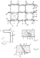
- Fig. 1 shows a detail of a plan view of an installation floor with an embodiment of a laying pattern.
- FIG. 2 shows a corner area of a base plate for the laying pattern of FIG. 1.
- FIG. 3 and 4 show two embodiments of the butt joint area between two floor panels in a section of the installation floor of FIG. 1.
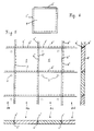
- FIG. 5 shows a section of a top view of an installation floor with a further embodiment of an installation pattern.
- FIG. 6 shows a top view of a base plate for the laying pattern from FIG. 5.
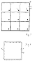
- Fig. 7 shows a detail of a plan view of an installation floor with a third embodiment of an installation pattern.
- FIG. 8 shows a top view of a base plate for the laying pattern of FIG. 7.
- FIG. 11 shows in perspective an embodiment of a support for the installation floor.
- 15 to 17 show a side view of a further embodiment of a support for an installation floor and parts thereof.
- FIG. 21 shows an anti-rotation device for the supports according to the embodiments of FIGS. 18 to 20.
- the installation floor shown in Fig. 1 comprises a layer of a plurality of the same, rectangular or, as shown, in particular square floor panels 1, the grid lines 2 ', 2''in a predetermined grid corresponding to intersecting at right angles an elevation formed from supports 3 are arranged while leaving receiving spaces 4 for installation lines.
- the base plates 1 are provided at the four corners with bevels 5 over 45 ° and also with a circumferential step fold 6. As a result, a surface 7 'of the base plate 1 exceeds the grid dimension by half the fold width on all sides, while the opposite, smaller surface 7' 'of the base plate 1 falls below the grid dimension on all sides by half the fold width.
- the bevels 5 practically cross the grid line cross 2 ', 2' 'at 45 °.
- the bevels 5 thus generally extend over a relatively small corner area such that the centers of the bevels 5 are arranged in accordance with the grid.
- the base plates 1 are arranged in both directions of the grid line cross 2 ', 2' 'alternately with the larger or the smaller surface 7' or 7 '' facing upwards in the joint overlap. This avoids bending under load and the resulting gaping of the butt joints between the floor panels 1, resulting in the overall appearance of a closed surface.
- the base plates 1 are expediently supported with step folds 6 protruding on the underside adjacent to their four corners by a respective support 3, while the base plates 1 which can be directly supported or supported are supported with step folds 6 protruding on the top side only by the base plates 1 with the step folds 6 protruding on the underside .
- every second base plate 1, namely all those with the large surface 7 ', can be picked up like a checkerboard for subsequent installation or revision purposes without further damage and without destruction. If necessary, the remaining base plates 1 can then also be accommodated.
- the installation floor shown in Fig. 5 also comprises a plurality of substantially square floor panels 1, all of which in this embodiment have a step fold 6 'directed to one side on one side edge and a step fold 6' 'directed to the other side on the three remaining side edges Have circumferential design, the width of the step folds 6 ', 6' 'being the same everywhere.
- the floor slabs 1 are laid in a route such that in each route 8a, 8b, 8c, 8d the step fold 6 'located only on one side edge is located on the same side of the floor slabs 1 running transversely to the longitudinal direction of the route.
- the floor slabs 1 are alternately laid with the step fold 6 'upwards and the other downwards, the step fold 6' in the respective route 8a, 8b, 8c, 8d on the step fold 6 'of the next floor plate 1 of this route side facing away.
- the base plates 1 with their step folds 6 ′′ of a route 8b, 8d projecting on the upper side lie in the longitudinal direction on the step folds 6 ′′ of the base plates 1 of neighboring routes 8a, 8c which extend in the longitudinal direction of the route and extend on the upper side.
- the step folds 6 ′′ of the base plates 1 of the respective route projecting on the upper side in the longitudinal direction of the path lie on the step folds 6 ′′ of the base plates 1 of the same route projecting in the longitudinal direction on the underside.
- the base plates 1 are expediently supported with step folds 6 ′′ on the underside on three sides, adjacent to two corners between two adjacent sides with step folds 6 ′′ protruding on the underside, each by a support 3, while the floor plates 1, which can be received in the manner of a path, have cantilevers on three sides Step folds 6 ′′ are supported by the base plates 1 with the step folds 6 ′′ protruding on the underside on three sides.
- the overlying floor slabs 1 of the routes 8b, 8d can be taken up directly in a route.
- a plurality of substantially square base plates 1 are provided, all of which consist of two square plate parts offset diagonally from one another by a predetermined distance, as a result of which a step fold 6 'on two adjacent side edges and on the other two are provided a step fold 6 '' on the underside, as far as all the way round, is formed adjacent side edges, the width of the step folds 6 ', 6' 'being the same everywhere.
- the plate parts are of the same size and usually but not necessarily of the same thickness (which also applies to the two previously described embodiments).
- the base plates 1 are installed flush in such a way that the respective top fold 6 'of a base plate running over two side edges of a base plate 1 on the bottom folds 6' 'of two bottom plates 1 which run adjacent to the side edges with the step fold 6 'are located.
- the step folds 6 ′′ on the underside of a row of base plates 1 laid in this way form a continuous support strip for the latter on the side to be connected in each case for the next row of base plates 1.
- the base plates 1 are expediently supported in each case with a support 3 adjacent to a corner between the two sides on which the step fold 6 ′′ projecting on the underside is located.
- the different laying patterns according to FIGS. 1, 5 and 7 can be used side by side in partial areas according to the respective requirements, for example the embodiment of FIG. 5 in corridors and that of FIGS. 1 and 7 in adjoining rooms. Depending on the requirements, they can also be used together with partial floor areas which are formed by means of a liquid screed (raised or not raised). In particular, areas which can be accommodated in the form of a line according to FIG. 5 are provided within permanently installed areas according to FIG. 7, while areas according to FIG. In the transition areas between different laying patterns or other areas, floor slabs adapted to the circumference should be used.
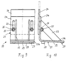
- the edge supports 20 can, for example, be designed in accordance with the embodiment shown in FIGS. 9 and 10.
- an angle 21 is provided, which is stiffened by struts 22 and is provided in its upright leg 21a with two vertical elongated holes 23, which are used for the height-adjustable accommodation of an adjustment plate 24.
- the latter has two welded-on bolts 25 which extend through the elongated holes 23 and are fastened to the leg 21a via nuts 26.
- the substantially horizontal leg 21b of the angle 21 is provided adjacent to its edge facing away from the leg 21a with recessed feet 27 and on the opposite edge adjacent to the leg 21a with one or more, relatively rigid spring elements 28, for example made of hard rubber.
- it has a bore 29 for fastening the angle 21 by means of a screw and a dowel (not shown) in the underbody.
- edge supports 20 or their adjustment plates 24 absorb the horizontal forces from the base plates 1 supported therefrom in the horizontal direction and divert them into the sub-floor, so that neither space-delimiting walls have to do this, nor is there a risk of receiving floor plates 1 that can be received
- Floor plates 1 of the part of the respective laying pattern not recorded move so that their position is not preserved, and all associated floor plates 1 later relocated and not only the recorded ones would simply have to be used again.
- Edge supports 20 are also useful, for example, to define an expansion joint every 15 to 20 m.
- step folds 6, 6 ', 6' ' are each expediently provided with chamfers 9 or curves on the edges of the respective horizontal fold section 6a.
- the step fold 6, 6 ', 6''of the base plate 1 can run obliquely, in particular one of the two inclined surfaces 6b of the step fold 6, 6', 6 '' having a larger angle the horizontal than the other inclined surface 6c, so that, in contrast to the embodiment of FIG. 3, there is only one support in the area of the horizontal folding section 6a.
- a design according to FIG. 3 or 4 serves to ensure an improved flow of force and to avoid point bearings between the load-bearing and base plate 1 carried thereby.
- the base plates 1 are expediently in one piece, in which case they can be manufactured as cuboids, after which the step folds 6, 6 ', 6' 'are attached by milling. However, they can also be produced by gluing two appropriately dimensioned plate parts.
- the base plates 1 consist of mineral material which is bound by a hydraulic binder, in particular by calcium sulfate alpha hemihydrate, and are in particular gypsum fiber boards, but other building materials such as calcium hydrosilicate-bound building materials can also be used.
- the base plates 1 can optionally be glued to one another in the area of the fold composite.
- Installations serving as work place supply, such as electrical outlets, can be used in openings which are provided or fitted in corresponding base plates 1.
- the supports 3 can be leveled in a simple manner despite flatness tolerances, so that even large tolerances of an underbody can be easily accommodated
- the supports 3 comprise a spherical cap 10, either directly or via an associated part provided with a spherical cap 10 part
- Base plate 1 is supported adjacent to a corner thereof, ie at the same time that each support 3 supports only one and not several base plates 1 at the same time, so that base plates 1 or sides not supported by supports 3 are only carried by other base plates 1. At the same time, this results in less assembly effort compared to supports which are arranged at the abutting corners of floor slabs to support several of them.
- the calotte 10 can be located on any part of the support 3, so can its foot, its shaft or a separate support part wear the calotte 10 or be designed as such. If the associated base plate 1 is supported via a part provided with a surface complementary to the spherical cap 10, the latter is preferably movable with respect to the spherical cap 10 in order to be able to align itself automatically with the plane of the base plate 1.
- the support 3 shown in Fig. 11 comprises a foot 11 with a central recess 12 for receiving an insertable shaft shell 13 and the spherical cap 10 with a flat top 14.
- the foot 11 has a top 15 which is conical towards the recess 12 and a large one Footprint at a low height on the outer edge.
- the foot 11 is round in plan view in the illustrated embodiment, it can also be square or hexagonal in plan view, for example. It consists of a mineral, hydraulically set material, in particular based on calcium sulfate alpha hemihydrate.
- the shaft jacket 13 expediently consists of cardboard or a comparable material serving as formwork and is inserted into the recess 12, the insertion depth being selected according to the requirements. For this purpose, it is expedient if there is a frictional engagement between the recess 12 and the shaft jacket 13, so that the shaft jacket 13 remains at the desired height without any further aids.
- a scale 16, for example printed on, can serve as an aid in obtaining the desired insertion depth.
- the dome 10 is placed with its curved part down on the shaft jacket 13 and also consists of a mineral, hydraulically set material, in particular based on calcium sulfate alpha hemihydrate, and can be provided with a central funnel 17.
- the shaft casing 13 can be filled essentially with mortar, after which the calotte 10 is placed on it, so that part of the mortar can penetrate the funnel 17. This can be followed by fine leveling and horizontal leveling before the mortar has hardened.
- the shaft jacket 13 can also be a hollow cylinder made of a mineral, hydraulically set building material, in particular based on it of calcium sulfate alpha hemihydrate, which can also have a sufficient wall thickness to be able to absorb the intended load without being poured with mortar.
- a fully cylindrical shaft can also be used.
- a recess for rotatably and tiltably accommodating the calotte 10 is to be provided at its upper end, this recess optionally receiving a mortar bed for the calotte 10 or also a shell-like insert, for example made of a sound-absorbing material such as a plastic. If desired, mortar filled into the hopper 17 allows the shaft and the cap 10 to be firmly connected to one another.
- a plate made of an impact sound-decoupling material such as a plastic or the like be attached on the flat top 14 of the calotte 10.
- the support 3 shown in FIG. 12 comprises a columnar foot 11, which can consist of a disk-shaped base element 11a and an attachment 11b.
- Base element 11a and attachment 11b are expediently round disks, preferably of the same diameter (however, disks can also be used differently, for example polygonal-shaped disks) and consist of mineral, hydraulically set material, for example based on gypsum and in particular on calcium sulfate alpha hemihydrate, the hardness of which is advantageous here is.
- the base elements 11a can be added up to the planned height.
- the top 11b can carry a plate-shaped impact sound protection 34 made of an elastomer material on the upper side.
- the attachment 11b carries a sleeve 29 which is provided with an external thread and which can be provided on the upper side with a transverse wall which bears against the top of the impact sound insulation 34.
- a spherical cap 10 which is provided with an internal thread in its circumferential part, is screwed onto the sleeve 29 and can be adjusted in height by rotating it relative to the sleeve 29 relative to the attachment 11b.
- the calotte 10 expediently has a circumferential, optionally corrugated bead 35 for better actuation.
- the support 3 shown in FIG. 13 includes a foot 11 a central, threaded recess 12 for receiving a screw-in, hollow cylindrical, correspondingly threaded shaft 13 and a spherical cap 10 with a flat surface 14.
- the spherical surface of the spherical surface 10 rests on the correspondingly chamfered upper edge of the shaft 13 and is thus movable relative to this, so that the flat surface 14 on the top of the calotte 10 can be easily aligned horizontally. Impact sound insulation can be placed on the flat surface 14 or integrated into it.
- Foot 11 is provided on the upper side with a circumferential flange 36, which leads to better handling when leveling.
- Foot 11 and shaft 13 are metal parts, this preferably also applies to the spherical cap 10, although this can also be made of a mineral, hydraulically set building material. In particular, these are castings, if appropriate, apart from the shaft 13, which in particular can also be rolled.
- the spherical surface 10 is directed upwards and inserted into the shaft 13 with a pin-like extension 37.
- the calotte 10 carries a complementary attachment 38, which has a flat upper side 39 and is movable relative to the calotte 10, so that it can be aligned horizontally with the flat upper side 39 by placing a base plate 1.
- the support 3 shown in FIGS. 15 to 17 comprises a columnar shaft 40, which consists of two shaft elements 40a, 40b and carries a calotte 10, which can carry a correspondingly curved part 41 on the underside, movable on the calotte 10.
- These parts all have a circular cross section and consist of mineral, hydraulically set material, for example based on gypsum and, in particular, on calcium sulfate alpha hemihydrate, the hardness of which is advantageous here.
- a connection to a sub-floor can be made using adhesive or mortar.
- the two parts 10 and 41 can be arranged below or above the shaft elements 40a, 40b.
- the calotte 10 can also be made in one piece with the shaft element 40b be trained.
- the shaft element 40a provided with an axially extending, central, cylindrical recess 42 has on the side facing the shaft element 40b three circumferentially arranged one behind the other, extending over 120 °, helically wound gradients 43 with the same pitch and the same initial and final height.
- the shaft element 40b is designed correspondingly with respect to the pitch gears 43, but has a central guide pin 44 which is received by the opening 42, so that there is an internal guide.
- the shaft elements 40a, 40b can thus be adjusted in height by rotating them against one another.
- the gradient gears 43 preferably have a rough surface, which can be designed in particular as a sawtooth-shaped step.
- the shaft elements 40a, 40b can optionally be surrounded by a sheath, for example made of plastic, which was used as formwork.
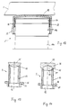
- supports 3 shown in FIGS. 18 to 21 each comprise a foot 11 made of mineral material which is bound by a hydraulic binder, in particular calcium sulfate alpha hemihydrate, which is provided with a central, vertically extending recess 12, and two metallic parts which can be screwed against each other for height adjustment, one part of which is inserted into and supported by the recess 12 of the foot 11, while the other part supports the associated base plate 1, one of the two parts forming the calotte 10.
- a hydraulic binder in particular calcium sulfate alpha hemihydrate
- a screw 19 which is produced in one piece by rolling, is provided with a hat 47 formed in one piece with it, which is in engagement with a nut 18 designed as a support nut.
- the nut 18 has on the upper side a flange 48 which rests on the foot 11, while the recess 12 receives the nut 18.
- the flange 48 can have lugs 49 which are bent in the direction of the foot 11 and are received by recesses 50 which adjoin the recess 12 laterally, in order thus to prevent the nut 18 from rotating form.
- the cap 47 of the screw 19 is slightly curved upwards in order to form the calotte 10 through this curved surface.
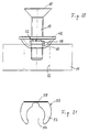
- the screw 19 is expediently secured against rotation by an anti-rotation device 52, as shown in FIG. 21.
- This is an approximately U-shaped clamp with two arms 53 which can be pushed outwards and which delimit a recess 54 corresponding to the inside diameter of the thread of the screw 19.
- the anti-rotation device 52 is inserted into the thread of the screw 19 adjacent to the nut 18, a raised section 55 being helpful.
- the hat 47 can also be made separately and optionally laterally cantilevered to the desired extent relative to the screw 19 and fastened, for example, by being pressed onto the screw 19.
- the screw 19 is provided with the spherical cap 10, which here represents a round head for the screw 19, while a plate 56 with a central section 57, which is curved in accordance with the round head, is supported thereon.
- the plate 56 can be pivoted and moved on all sides on the round head by means of tabs 58 and has a peripheral edge region 59 for supporting an associated base plate 1.
- the flange 48 fastened on the underside to the nut 18 comprises the cap 10, which is inserted into the recess 12, so that the nut 18 can be pivoted on all sides.
- the screw 19 has a flat support surface 60 for an associated base plate 1, the support surface 60 by a countersunk head (as shown) or by a flat hat, plate or the like. can be formed.
- the radius of the curvature of the spherical cap 10, if it directly supports a base plate 1, is preferably chosen such that the spherical cap 10 still lies approximately tangentially on the base plate 1 at the edge at a maximum permissible inclination of the support 3 of, for example, 10%.
- a protective ring 61 made of mineral material, for example of the same material as that of the foot 11, can be arranged around supports 3, which comprise metallic parts, for fire protection reasons. be arranged, the protective ring 61 in the longitudinal direction of the support 3 is divided into two halves, which are placed around the installed support 3 carrying a base plate 1 on the sub-floor, so that a relatively small gap between the top of the protective ring 61 and the base plate 1 remains.
Landscapes
- Engineering & Computer Science (AREA)
- Architecture (AREA)
- General Engineering & Computer Science (AREA)
- Civil Engineering (AREA)
- Structural Engineering (AREA)
- Floor Finish (AREA)
Priority Applications (1)
| Application Number | Priority Date | Filing Date | Title |
|---|---|---|---|
| EP97115070A EP0828038A3 (fr) | 1996-09-04 | 1997-08-30 | Support pour faux plancher |
Applications Claiming Priority (20)
| Application Number | Priority Date | Filing Date | Title |
|---|---|---|---|
| DE19620255 | 1996-05-21 | ||
| DE19620255 | 1996-05-21 | ||
| DE19623985A DE19623985C1 (de) | 1996-06-15 | 1996-06-15 | Hohlraumbodenstütze |
| DE19623985 | 1996-06-15 | ||
| DE19626571 | 1996-07-02 | ||
| DE1996126570 DE19626570C1 (de) | 1996-07-02 | 1996-07-02 | Hohlraumboden |
| DE19626570 | 1996-07-02 | ||
| DE19626571 | 1996-07-02 | ||
| DE1996131231 DE19631231A1 (de) | 1996-08-02 | 1996-08-02 | Hohlraumboden |
| DE19631231 | 1996-08-02 | ||
| DE19631880 | 1996-08-07 | ||
| DE1996131880 DE19631880C2 (de) | 1996-08-07 | 1996-08-07 | Hohlraumbodenstütze |
| DE1996148100 DE19648100C1 (de) | 1996-11-21 | 1996-11-21 | Installationsbodenstütze |
| DE19648101 | 1996-11-21 | ||
| DE19648103 | 1996-11-21 | ||
| DE19648100 | 1996-11-21 | ||
| DE19648101A DE19648101C1 (de) | 1996-11-21 | 1996-11-21 | Installationsbodenstütze |
| DE19648103 | 1996-11-21 | ||
| DE19718061 | 1997-04-29 | ||
| DE1997118061 DE19718061C1 (de) | 1997-04-29 | 1997-04-29 | Installationsbodenstütze |
Publications (1)
| Publication Number | Publication Date |
|---|---|
| EP0808962A1 true EP0808962A1 (fr) | 1997-11-26 |
Family
ID=27579206
Family Applications (1)
| Application Number | Title | Priority Date | Filing Date |
|---|---|---|---|
| EP97108191A Withdrawn EP0808962A1 (fr) | 1996-05-21 | 1997-05-21 | Faux plancher |
Country Status (3)
| Country | Link |
|---|---|
| EP (1) | EP0808962A1 (fr) |
| CA (1) | CA2227406A1 (fr) |
| WO (1) | WO1997044550A1 (fr) |
Families Citing this family (2)
| Publication number | Priority date | Publication date | Assignee | Title |
|---|---|---|---|---|
| US7717395B2 (en) * | 2004-09-16 | 2010-05-18 | Robert L. Rowan & Associates, Inc. | Adjustable support apparatus for machinery |
| CN113846199A (zh) * | 2021-09-30 | 2021-12-28 | 上海宝冶集团有限公司 | 一种多边企口的铸石板及其铺贴方法 |
Citations (11)
| Publication number | Priority date | Publication date | Assignee | Title |
|---|---|---|---|---|
| DD74092A (fr) * | ||||
| DE1659314A1 (de) * | 1967-12-08 | 1971-09-23 | Glischke Reinhold | Halter fuer plattenartige Bauelemente |
| EP0081960A1 (fr) * | 1981-12-12 | 1983-06-22 | David George Godfrey | Cric de support |
| FR2528895A1 (fr) * | 1982-06-21 | 1983-12-23 | Maillet Expositions Sa | Element de plancher modulaire juxtaposable et gerbable |
| DE3709017A1 (de) * | 1987-03-19 | 1988-10-06 | Lindner Ag Decken Boden Trennw | Hoehenverstellbares stuetzelement |
| EP0309399A1 (fr) * | 1987-09-23 | 1989-03-29 | Zurecon Ag | Support pour un faux plancher surélevé |
| DE3926978C1 (en) * | 1989-08-16 | 1990-07-19 | Goldbach Gmbh, Holz-, Kunststoff- Und Metallverarbeitung, 8758 Goldbach, De | Height-adjustable flooring support - comprises two coaxially rotating parts which rest on one another and whose surfaces are held by stop faces |
| DE4001806A1 (de) * | 1990-01-23 | 1991-07-25 | Gerhard Stroer | Stuetzelement fuer lose verlegte bodenplatten |
| DE4001636A1 (de) * | 1990-01-20 | 1991-08-01 | Meissl Geb Goettlert Christine | Hohlraumboden |
| DE4021963A1 (de) * | 1990-07-10 | 1992-01-16 | Lindner Ag | Hohlraumboden |
| EP0641903A1 (fr) * | 1993-09-02 | 1995-03-08 | MERO-Werke Dr.-Ing. Max Mengeringhausen GmbH & Co. | Faux plancher surélevé |
-
1997
- 1997-05-21 EP EP97108191A patent/EP0808962A1/fr not_active Withdrawn
- 1997-05-21 CA CA002227406A patent/CA2227406A1/fr not_active Abandoned
- 1997-05-21 WO PCT/EP1997/002588 patent/WO1997044550A1/fr not_active Ceased
Patent Citations (11)
| Publication number | Priority date | Publication date | Assignee | Title |
|---|---|---|---|---|
| DD74092A (fr) * | ||||
| DE1659314A1 (de) * | 1967-12-08 | 1971-09-23 | Glischke Reinhold | Halter fuer plattenartige Bauelemente |
| EP0081960A1 (fr) * | 1981-12-12 | 1983-06-22 | David George Godfrey | Cric de support |
| FR2528895A1 (fr) * | 1982-06-21 | 1983-12-23 | Maillet Expositions Sa | Element de plancher modulaire juxtaposable et gerbable |
| DE3709017A1 (de) * | 1987-03-19 | 1988-10-06 | Lindner Ag Decken Boden Trennw | Hoehenverstellbares stuetzelement |
| EP0309399A1 (fr) * | 1987-09-23 | 1989-03-29 | Zurecon Ag | Support pour un faux plancher surélevé |
| DE3926978C1 (en) * | 1989-08-16 | 1990-07-19 | Goldbach Gmbh, Holz-, Kunststoff- Und Metallverarbeitung, 8758 Goldbach, De | Height-adjustable flooring support - comprises two coaxially rotating parts which rest on one another and whose surfaces are held by stop faces |
| DE4001636A1 (de) * | 1990-01-20 | 1991-08-01 | Meissl Geb Goettlert Christine | Hohlraumboden |
| DE4001806A1 (de) * | 1990-01-23 | 1991-07-25 | Gerhard Stroer | Stuetzelement fuer lose verlegte bodenplatten |
| DE4021963A1 (de) * | 1990-07-10 | 1992-01-16 | Lindner Ag | Hohlraumboden |
| EP0641903A1 (fr) * | 1993-09-02 | 1995-03-08 | MERO-Werke Dr.-Ing. Max Mengeringhausen GmbH & Co. | Faux plancher surélevé |
Also Published As
| Publication number | Publication date |
|---|---|
| CA2227406A1 (fr) | 1997-11-27 |
| WO1997044550A1 (fr) | 1997-11-27 |
Similar Documents
| Publication | Publication Date | Title |
|---|---|---|
| DE69702681T2 (de) | Modulares Element zur Unterstützung und Lüftung von Decken | |
| DE2243102C3 (de) | Aus Platten zusammengesetzter, auf einem festen Rohboden aufgeständerter Unterboden mit höhenverstellbaren Tragvorrichtungen | |
| DE29615755U1 (de) | Verankerungselement für Stahlbetonbauten | |
| DE1196345B (de) | Verfahren zum Einbau von Stuetzen fuer auf-gestaenderte Plattenfussboeden sowie Kopfplatten und Montagelehren zur Durchfuehrung des Verfahrens | |
| DE3837849A1 (de) | Schalungsplatte zur verwendung als verlorene schalung fuer die herstellung eines hohlraumbodens | |
| DE102012101366B3 (de) | Unterflur-Schacht, Bausatz zum Herstellen und Verfahren zum Einbau dafür | |
| DE10216914C1 (de) | Bausatz zur Herstellung von Tragkonstruktionen für Abdeckroste | |
| DE2107898A1 (de) | Fußboden, der aus einer Vielzahl von auf recht stehenden Stutzgliedern und darauf abge stutzten Fußbodenplatten gebildet ist | |
| DE19549535C2 (de) | Justiervorrichtung zum Setzen eines Wandelements | |
| DE19747080C1 (de) | Installationsbodenstütze | |
| WO1997044550A1 (fr) | Revetement de sol | |
| DE9409626U1 (de) | Balkonkonstruktion | |
| EP1083269A2 (fr) | Aides pour la pose de revêtements en plaques en position surélevée ou ventilée | |
| WO2010075855A1 (fr) | Système de goujon pour construction en béton | |
| EP3430304A1 (fr) | Élément socle pour recevoir avec transfert de charge un module de boîtier d'un distributeur automatique | |
| EP0826851A2 (fr) | Plancher surélevé | |
| DE19629340C2 (de) | Hohlraumbodenstütze | |
| DE10035823A1 (de) | Schalungsträger | |
| DE19808092A1 (de) | Vorrichtung für die Anpflanzung von Bäumen und dgl. | |
| DE19634960A1 (de) | Schacht mit Höhenausgleich | |
| DE2147039A1 (de) | Beton-fertigteile fuer ein estrichunterflur-system | |
| DE19623985C1 (de) | Hohlraumbodenstütze | |
| DE19635820A1 (de) | Feinjustierungseinrichtung für einen Installationsboden | |
| DE19718061C1 (de) | Installationsbodenstütze | |
| DE8913789U1 (de) | Installationsboden |
Legal Events
| Date | Code | Title | Description |
|---|---|---|---|
| PUAI | Public reference made under article 153(3) epc to a published international application that has entered the european phase |
Free format text: ORIGINAL CODE: 0009012 |
|
| AK | Designated contracting states |
Kind code of ref document: A1 Designated state(s): AT BE CH DE DK ES FI FR GB GR IE IT LI LU NL PT SE |
|
| 17P | Request for examination filed |
Effective date: 19980211 |
|
| RAP3 | Party data changed (applicant data changed or rights of an application transferred) |
Owner name: PROMINERAL GESELLSCHAFT ZUR VERWENDUNG VON MINERA Owner name: SICOWA VERFAHRENSTECHNIK FUER BAUSTOFFE GMBH & CO. |
|
| 17Q | First examination report despatched |
Effective date: 20010201 |
|
| STAA | Information on the status of an ep patent application or granted ep patent |
Free format text: STATUS: THE APPLICATION IS DEEMED TO BE WITHDRAWN |
|
| 18D | Application deemed to be withdrawn |
Effective date: 20010612 |