EP0808970A2 - Serrure à cylindre - Google Patents
Serrure à cylindre Download PDFInfo
- Publication number
- EP0808970A2 EP0808970A2 EP96118819A EP96118819A EP0808970A2 EP 0808970 A2 EP0808970 A2 EP 0808970A2 EP 96118819 A EP96118819 A EP 96118819A EP 96118819 A EP96118819 A EP 96118819A EP 0808970 A2 EP0808970 A2 EP 0808970A2
- Authority
- EP
- European Patent Office
- Prior art keywords
- cylinder
- plug
- lock according
- cylinder lock
- cylinder core
- Prior art date
- Legal status (The legal status is an assumption and is not a legal conclusion. Google has not performed a legal analysis and makes no representation as to the accuracy of the status listed.)
- Granted
Links
- 229910000831 Steel Inorganic materials 0.000 claims description 38
- 239000010959 steel Substances 0.000 claims description 38
- 239000007787 solid Substances 0.000 claims description 26
- 230000001681 protective effect Effects 0.000 claims description 23
- 239000000463 material Substances 0.000 claims description 15
- 230000004323 axial length Effects 0.000 claims description 8
- 239000010935 stainless steel Substances 0.000 claims description 5
- 229910001220 stainless steel Inorganic materials 0.000 claims description 5
- KUNSUQLRTQLHQQ-UHFFFAOYSA-N copper tin Chemical class [Cu].[Sn] KUNSUQLRTQLHQQ-UHFFFAOYSA-N 0.000 claims description 4
- 229910052750 molybdenum Inorganic materials 0.000 claims description 4
- 229910052804 chromium Inorganic materials 0.000 claims description 3
- 238000005516 engineering process Methods 0.000 claims description 3
- 230000003313 weakening effect Effects 0.000 claims description 3
- 239000000853 adhesive Substances 0.000 claims description 2
- 230000001070 adhesive effect Effects 0.000 claims description 2
- 238000006243 chemical reaction Methods 0.000 claims description 2
- 239000000203 mixture Substances 0.000 claims 2
- 229910045601 alloy Inorganic materials 0.000 claims 1
- 239000000956 alloy Substances 0.000 claims 1
- 238000010276 construction Methods 0.000 claims 1
- 230000000704 physical effect Effects 0.000 claims 1
- 235000019589 hardness Nutrition 0.000 description 6
- 229910000906 Bronze Inorganic materials 0.000 description 4
- 229910052759 nickel Inorganic materials 0.000 description 4
- 239000010974 bronze Substances 0.000 description 3
- 229910052751 metal Inorganic materials 0.000 description 3
- 239000002184 metal Substances 0.000 description 3
- 229910001369 Brass Inorganic materials 0.000 description 2
- 239000010951 brass Substances 0.000 description 2
- 230000000694 effects Effects 0.000 description 2
- 238000010521 absorption reaction Methods 0.000 description 1
- 230000006835 compression Effects 0.000 description 1
- 238000007906 compression Methods 0.000 description 1
- 238000005553 drilling Methods 0.000 description 1
- 238000002474 experimental method Methods 0.000 description 1
- 239000002360 explosive Substances 0.000 description 1
- 238000009434 installation Methods 0.000 description 1
- 229910000734 martensite Inorganic materials 0.000 description 1
- 150000002739 metals Chemical class 0.000 description 1
- 238000000034 method Methods 0.000 description 1
- 230000009467 reduction Effects 0.000 description 1
- 238000005096 rolling process Methods 0.000 description 1
- 229910052721 tungsten Inorganic materials 0.000 description 1
- 239000010937 tungsten Substances 0.000 description 1
- -1 tungsten carbides Chemical class 0.000 description 1
Images






Classifications
-
- E—FIXED CONSTRUCTIONS
- E05—LOCKS; KEYS; WINDOW OR DOOR FITTINGS; SAFES
- E05B—LOCKS; ACCESSORIES THEREFOR; HANDCUFFS
- E05B17/00—Accessories in connection with locks
- E05B17/20—Means independent of the locking mechanism for preventing unauthorised opening, e.g. for securing the bolt in the fastening position
- E05B17/2084—Means to prevent forced opening by attack, tampering or jimmying
-
- E—FIXED CONSTRUCTIONS
- E05—LOCKS; KEYS; WINDOW OR DOOR FITTINGS; SAFES
- E05B—LOCKS; ACCESSORIES THEREFOR; HANDCUFFS
- E05B27/00—Cylinder locks or other locks with tumbler pins or balls that are set by pushing the key in
-
- E—FIXED CONSTRUCTIONS
- E05—LOCKS; KEYS; WINDOW OR DOOR FITTINGS; SAFES
- E05B—LOCKS; ACCESSORIES THEREFOR; HANDCUFFS
- E05B17/00—Accessories in connection with locks
- E05B17/0054—Fraction or shear lines; Slip-clutches, resilient parts or the like for preventing damage when forced or slammed
- E05B17/0062—Fraction or shear lines; Slip-clutches, resilient parts or the like for preventing damage when forced or slammed with destructive disengagement
Definitions
- the invention relates to a cylinder lock, in particular for use on protective devices and traps for slot machines and vending machines, on lattice rolling gates, on movable protective grilles or the like, with a cylinder housing in which a with a cylinder core with a key channel running in the direction of the axis in one on both ends of the Cylinder housing opening opening is rotatably arranged, which can be rotated by a limited amount in the circumferential direction by a flat key to be inserted into the key channel, with several rows of cased and / or adjacent housing pins and associated core pins that form pin tumblers, and with a slide bolt that can be driven by the cylinder core , wherein the plug cylinder lock is arranged in at least one receiving opening of the object to be secured and locked there.
- Mortise cylinder locks of the required type are known through a variety of designs. These plug-in cylinder locks, however, are relatively easy and quick to break open, despite the arrangement of numerous housing and core pins, for example by screwing a screw into the key channel, by means of which the cylinder core can be pulled out of the cylinder housing. The pin tumblers are sheared off, the slide bolt is bent and torn off and also torn out of the housing.
- the invention has for its object to make a plug-in cylinder lock of the required type much more burglar-proof.
- the outer jacket of the cylinder housing is deformed in the event of a break-in and the walls in the region of the end-face bore are pressed inwards.
- the slide bolt is either sheared off or bent so far that it can be torn out of the opening of the object to be protected relatively easily. The whole lock can then be pulled out of the opening.
- the explosive forces that occur are approximately uniformly transmitted to the wall of the bore and thus to the cylinder jacket, with such large forces that the cylinder is destroyed and the slide bolt torn off and sheared off even under the given conditions with the strongest wall design becomes. It must be taken into account that in the case of protective devices and traps for gaming machines and vending machines or the like, the installation conditions are determined. In particular, the distance fixed between the slide bolt and an inner wall of the object to be protected and cannot be enlarged as desired, so that one is very limited in the area of the inner end section of the plug-in cylinder with regard to constructive measures.
- the result of the invention is that the high deformation forces which occur and which are transmitted to the inner end section of the cylinder housing in the event of a break-in are evenly absorbed by the support disk.
- the support disc prevents deformation of the cylinder housing.
- a tensile force applied to the plug-in cylinder lock in the longitudinal axis direction can deform the slide bolt. Characterized in that a tangential surface is present at the end inner end of the cylinder housing, it is achieved that the slide bolt can lay down and be supported on this surface, so that in the further course of the attempt to break open the slide bolt acts like a wedge in the receiving opening for the plug-in cylinder , that is, the cylinder lock cannot be pulled out of the opening of the object.
- the support disk is supported on its circumference evenly on all sides on a shape-matched inner wall of the cylinder housing.
- the support disk is arranged with a press fit in the opening of the cylinder housing.
- the support disc is screwed into a thread of the receiving opening.
- the support disc is glued in, while it is soldered in the embodiment according to claim 6 and welded in the embodiment according to claim 7 .
- the cylinder housing is provided with a plurality of steps or shoulders into which a form-adapted support body in the form of a disc engages, so that this not only stiffens and supports the cylinder housing radially but also axially in this area - Claim 8 .
- the support disc is arranged in an arranged at the inner end of the cylinder housing, enlarged in diameter of the cylinder housing.
- the support disc consists of armored steel weapon technology, for example as it is used for the casing of battle tanks.
- the support disc can also consist of a very hard, high-tempered special steel, in particular armored steel.
- Such steels can be, for example, martinsite-hardenable steels.
- a martinsite-hardening steel can have the following characteristics: Stretch limit 800 to 1000 N / mm 2 strength 1100 to 1300 N / mm 2 Elongation at break 15% Constriction 7 to 15% hardness 350 HB
- Such a martensitic steel can for example 5.0% Mo 18.0% Ni 10.0% Co 1.0% Ti 4-6% Mon 16-19% Ni 7-11% Co 0.3-1.5% Ti or for example 8 to 13% Cr, preferably 8.7 to 9.3% Cr 7.8 to 11% Ni, preferably 8.3 to 10.2% Ni 4.5 to 1% Mo, preferably 2.9 to 1.9% Mo 1.9 to 3.2% Co, preferably 2.0 to 3.1% Co 0.5 to 1.9% Ti, preferably 0.8% Ti exhibit.
- martinsite-hardenable steels are relatively tough and easy to deform in the solution-annealed condition, they are extremely hard in the heat-hardened condition. Such hardnesses can optionally be used for the support disks.
- sheet metal with extremely high hardness is normally limited due to the lack of weldability, but this does not matter here.
- the support disk is made of bronze.
- Bronze has a high pressure absorption capacity, does not burst as easily under pressure and does not deform as for example certain types of steel - claim 11 .
- CuSn8 is used as the material for the support disk.
- the material has at least a tensile strength of 390 to 750 N / mm 2 , preferably 690 N / mm 2 , a 0.2% proof stress of 290 to 700, preferably 640 N / mm 2 , an elongation at break from 60 to 10, preferably 10, and a Brinell hardness HB from 90 to 250, preferably 220.
- Claim 13 describes an advantageous embodiment.
- the protective cover arranged at the end face and facing outwards has a special shape, by means of which the cylinder core is further secured against being pulled outwards.
- the protective hood radially supports the outward-facing end region of the cylinder core.
- a cylinder core head is connected to the actual cylinder core by a predetermined breaking point, which occurs when an attempt is made to break in predetermined load is separable. In this way it is prevented that only predetermined forces can be transmitted to the storage for the plug-in cylinder lock in the event of a break-in attempt.
- Solid carbide pins prevent a pulling screw from being screwed into the cylinder core, for example. After a short distance, this hits a solid carbide pin and is deflected by it, so that the cutting edges of the drawing screw become blunt and cannot penetrate further into the material of the cylinder core.
- Claim 33 describes a special, inventive solution for the arrangement of solid carbide pins, which also applies to claim 34 .
- Claim 35 describes a further embodiment, in which the cylinder core head is coupled to the actual cylinder core by an adhesive connection, which can be separated when a predetermined load is exceeded.
- the cylinder core head is coupled to the cylinder core via a plurality of pins or screws which also tear off when a defined shear and / or tensile stress is exceeded.
- the predetermined breaking point is formed in the inventive solution according to claim 37 by weakening the cylinder core at a certain point. This weakening is formed by several radially directed recesses, for example bores. At this point, a predetermined breaking point is produced in this way, at which the cylinder core head can be separated from the cylinder core in a defined manner.
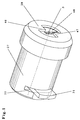
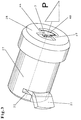
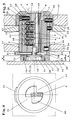
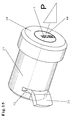
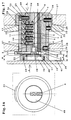
- the cylinder lock shown in the drawing has a cylinder housing 1 and a cylinder core 2 rotatably arranged therein in a bore, which has a longitudinally extending key channel 3, into which a flat key, not shown, can be inserted.
- the flat key can be designed as a longitudinal rib profile flat key and have a plurality of depressions through which it controls core pins 4, 5, 6, 7 and 8, which are arranged in the longitudinal axis direction of the cylinder core 2 and are parallel to one another in the blind bores of the cylinder core 2 and which are longitudinally displaceable Flat key facing ends are tapered (Fig. 5, 7).
- Housing pins 9, 10, 11, 12 and 13 are arranged coaxially to the core pins 4, 5, 6, 7 and 8 and are displaceable in bores of the cylinder housing 1 running parallel to one another.
- the housing pins 9 to 13 are each supported against the restoring force of compression springs, which are only indicated schematically in the drawing and which are each supported against the end face of the relevant housing pin 9 to 13 facing away from the associated core pin 4 to 8, so that the Core pins 4 to 8 are spring-loaded accordingly.
- the core pins 4 to 8 and the housing pins 9 to 13 form the pin tumblers of the cylinder lock.
- the thickness F measured in the axial direction is less than the axial length E of the opening 15 of the cylinder housing section 14.
- the screw 19 connects a slide bolt 21 to the cylinder core 2 in a gearbox manner.
- This slide bolt 21 emerges from a slot-shaped recess 22 of the cylinder housing 1 which extends circumferentially over a circular sector.
- the movement of the cylinder core 2 is limited by a stop pin 23 which, on the one hand, engages in a radial slot 24, which extends approximately by 90 degrees or another angle in the circumferential direction of the cylinder core 2 and, on the other hand, is arranged in a through bore 25 of the cylinder housing 1.
- the head of the stop pin 23 engages in a bore 26 which is arranged in a steel jacket sleeve 27 which encloses the cylinder housing 1 over most of its length.
- the protective hood 28 is connected to the steel jacket sleeve 27 and to the cylinder housing 1 by a plurality of radial pins 30 distributed over the circumference, which end at the outer periphery of the length section 29.
- a locking pin is arranged which engages in a slot 32 of a wall 33.
- the slot 32 extends in the axial longitudinal direction of the cylinder lock. Via this locking pin 31, the reaction forces which are transmitted to the plug-in cylinder lock via the flat key can be absorbed, so that the plug-in cylinder lock cannot twist.
- a further radial pin is arranged, which extends through a through bore 35 of the steel jacket sleeve 27 and engages in a blind bore 36 arranged coaxially thereto, which is arranged in the cylinder housing 1.
- walls of an object to be protected for example a slot machine, are indicated.
- the walls 33, 37 and 38 each have a through hole which are arranged coaxially to one another and into which the cylinder lock is inserted.
- the dimension X is generally fixed in slot machines, so that the distance between the end face 40 and the inside 41 of the wall 39 is generally small. Due to the fact that the dimension X is given constructively, there is normally little possibility of constructive design.
- the cylinder housing section 14 is provided on its diametrically opposite side with the locking position of the slide bolt 21 with a tangentially arranged surface 42 running in the direction of the axis of the cylinder housing 1, against which the slide bolt 21 is supported, placed on and supported during an attempted break-in can wedge if necessary.
- the design of the slide bolt 21 can be seen more clearly. From this it can be seen that the slide bolt 21 has a slot 43 which opens out laterally and into which the screw head 18 acts as an eccentric drive intervenes. The slide bolt 21 is guided through a radial groove. The slide bolt 21 is rounded on its top and bottom in each case according to a circular arc 44 or 45.
- the slide bolt 21 consists of stainless steel, for example X 5 CrNi 18 10, material number 1.4301.
- a steel is an austenitic steel which, when quenched, has the following properties at room temperature:
- the protective cover 28 has, in terms of material, integrally connected to it, radially directed sectors 46 or 47 or radial sectors, which face 48 facing outwards Cylinder core 2 overlap on part of its surface. In this way, the cylinder core 2 is still secured against axial pulling out.
- radial sectors 46 and 47 extend right up to the key channel 3, so that manipulations with intrusion tools are made more difficult.
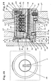
- FIGS. 13 to 25 For the embodiment shown in FIGS. 13 to 25, the same reference numerals have been used for parts with the same function as in the embodiment according to FIGS. 1 to 12.
- the operation of the embodiment according to FIGS. 13 to 25 thus corresponds fundamentally to the embodiment according to FIGS. 1 to 12, so that with regard to the basic structure and the operation of the plug-in cylinder lock, those made in connection with the embodiment according to FIGS. 1 to 12 Executions can be referenced.
- FIGS. 13 to 25 differs from the previously described embodiment as follows:
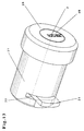
- the protective hood 28 is no longer provided with radial sectors 46, as in the embodiment according to FIGS. 1 to 12. Rather, the cylinder core 2 is provided at its outwardly facing end section with a cylinder core head 49 which is enlarged in diameter in the embodiment shown and which is integrally connected to the cylinder core 2 via a predetermined breaking point 50. If necessary, the cylinder core head 49 can also have the same diameter as the cylinder core 2.
- the predetermined breaking point 50 is formed by strip-shaped material parts present on both sides of the key channel 3, which in the exemplary embodiment shown is delimited outwards by walls 51 and 52 arranged parallel to one another and arranged symmetrically to the axis of rotation of the cylinder core 2.
- these walls 51, 52 are each formed by a radial groove 53 or 54.
- the axial width G can be 0.5 mm for each radial groove 53 or 54 in one embodiment.
- Both grooves 53 and 54 are of the same size and are arranged symmetrically to the longitudinal axis.
- the axial length H of the cylinder core head 49 is 6 mm in this embodiment, while the grooves 53 and 54 are arranged approximately at an axial distance of approximately the groove width G behind the cylinder core head 49.
- the design of the predetermined breaking point 50 can also be different
- predetermined breaking point 50 it is possible to provide more than two grooves.
- grooves 53 and 54 it is also possible to produce the predetermined breaking point 50 differently, for example by means of several bores which run parallel or at an angle to one another or by other cross-sectional reductions in the area of the predetermined breaking point or by using different materials for the cylinder core 2 and the cylinder core head 49.
- the cylinder core head 49 is provided next to the longitudinal center axis (axis of rotation) of the cylinder core 2 with a solid carbide pin 56 which is thus orthogonal to the axis of rotation of the cylinder core 2 and which is on the outer cylindrical surface of the cylinder core head 49 ends.
- the cylinder core 2 in the embodiment shown is provided on each side of its axis of rotation with a further solid carbide pin 57 and 58, respectively.
- these solid carbide pins 57, 58 can have the same dimensions, at least in diameter, as the solid carbide pin 56.
- the solid carbide pins 57 and 58 also each end on the outer cylindrical surface of the cylinder core 2, so that its rotation is not hindered.
- a hard metal not only hardened steels but also tungsten carbides and other well-known hard metals come into consideration.
- a pulling screw 55 is now screwed into the key channel 3, it is first deflected from its longitudinal axis by the solid carbide pin 56 (FIG. 25) and then either meets the solid carbide pin 57 or 58, and can therefore only over a small part of its length Key channel 3 - if at all - are screwed in so that the intended full pulling loads cannot be transferred to the cylinder core 2.
- the screw-in test thus generally ends at the solid carbide pin 57, so that only the cylinder core head 49 can be torn off at the predetermined breaking point 50.
- the cutting tips of the drawing screw 55 become blunt when screwed in by the solid carbide pin 56, so that they can no longer be screwed into the cylinder core head 49, which is usually made of brass, and the cylinder core 2, which is also made of brass. If a new pull screw 55 were used which does not yet have blunt cutting tips, this will hit in any case on the solid carbide pin 57 and can then also no longer be screwed in.
Landscapes
- Control Of Vending Devices And Auxiliary Devices For Vending Devices (AREA)
- Vehicle Body Suspensions (AREA)
- Chairs Characterized By Structure (AREA)
- Valve Device For Special Equipments (AREA)
- Connector Housings Or Holding Contact Members (AREA)
- Filling Or Discharging Of Gas Storage Vessels (AREA)
- Storage Of Web-Like Or Filamentary Materials (AREA)
Applications Claiming Priority (2)
| Application Number | Priority Date | Filing Date | Title |
|---|---|---|---|
| DE29609077U DE29609077U1 (de) | 1996-05-21 | 1996-05-21 | Steckzylinderschloß, insbesondere zur Verwendung an Schutzvorrichtungen und Fallen für Spiel- und Warenautomaten, an Gitterrolltoren, an beweglichen Schutzgittern o.dgl. |
| DE29609077U | 1996-05-21 |
Publications (3)
| Publication Number | Publication Date |
|---|---|
| EP0808970A2 true EP0808970A2 (fr) | 1997-11-26 |
| EP0808970A3 EP0808970A3 (fr) | 1998-05-27 |
| EP0808970B1 EP0808970B1 (fr) | 1999-08-11 |
Family
ID=8024199
Family Applications (1)
| Application Number | Title | Priority Date | Filing Date |
|---|---|---|---|
| EP96118819A Expired - Lifetime EP0808970B1 (fr) | 1996-05-21 | 1996-11-25 | Serrure à cylindre |
Country Status (3)
| Country | Link |
|---|---|
| EP (1) | EP0808970B1 (fr) |
| AT (1) | ATE183277T1 (fr) |
| DE (2) | DE29609077U1 (fr) |
Cited By (2)
| Publication number | Priority date | Publication date | Assignee | Title |
|---|---|---|---|---|
| EP0957219A1 (fr) | 1998-05-09 | 1999-11-17 | August Knapp Schliesstechnik GmbH | Serrure cylindrique encastrée, notamment pour utilisation dans les dispositifs de protection des machines de vente ou de jeu |
| US20220389738A1 (en) * | 2021-06-07 | 2022-12-08 | David Truffet | Lock structure and method of protection |
Families Citing this family (2)
| Publication number | Priority date | Publication date | Assignee | Title |
|---|---|---|---|---|
| DE102007062162B4 (de) | 2007-12-21 | 2014-03-20 | Jul.Niederdrenk Gmbh & Co.Kg | Wegfahrsperre |
| CN102661084A (zh) * | 2012-05-11 | 2012-09-12 | 章景林 | 防盗门锁弹子锁头 |
Family Cites Families (5)
| Publication number | Priority date | Publication date | Assignee | Title |
|---|---|---|---|---|
| JPS5284100A (en) * | 1976-01-06 | 1977-07-13 | Takigen Mfg Co | Lock device |
| FR2589926B1 (fr) * | 1985-11-14 | 1993-12-31 | Neiman Sa | Verrou a pistons a rotor coulissant embrayable avec un organe de commande |
| DE3835816A1 (de) * | 1988-10-21 | 1990-04-26 | Erich Mundhenke | Zylinderschloss |
| US5177466A (en) * | 1991-08-05 | 1993-01-05 | Lai Chung C | Lock structure with a warning device |
| AT405669B (de) * | 1995-03-03 | 1999-10-25 | Evva Werke | Aufbohrsicherung für zylinderschlösser |
-
1996
- 1996-05-21 DE DE29609077U patent/DE29609077U1/de not_active Expired - Lifetime
- 1996-11-25 AT AT96118819T patent/ATE183277T1/de not_active IP Right Cessation
- 1996-11-25 EP EP96118819A patent/EP0808970B1/fr not_active Expired - Lifetime
- 1996-11-25 DE DE59602711T patent/DE59602711D1/de not_active Expired - Lifetime
Non-Patent Citations (1)
| Title |
|---|
| None |
Cited By (2)
| Publication number | Priority date | Publication date | Assignee | Title |
|---|---|---|---|---|
| EP0957219A1 (fr) | 1998-05-09 | 1999-11-17 | August Knapp Schliesstechnik GmbH | Serrure cylindrique encastrée, notamment pour utilisation dans les dispositifs de protection des machines de vente ou de jeu |
| US20220389738A1 (en) * | 2021-06-07 | 2022-12-08 | David Truffet | Lock structure and method of protection |
Also Published As
| Publication number | Publication date |
|---|---|
| EP0808970B1 (fr) | 1999-08-11 |
| ATE183277T1 (de) | 1999-08-15 |
| EP0808970A3 (fr) | 1998-05-27 |
| DE59602711D1 (de) | 1999-09-16 |
| DE29609077U1 (de) | 1996-08-14 |
Similar Documents
| Publication | Publication Date | Title |
|---|---|---|
| DE60219774T2 (de) | Ventilsperrvorrichtung | |
| DE69311229T2 (de) | Geschraubter Sicherungsring für Rollenmeissel und Verfahren zur Herstellung eines solchen Meissels | |
| DE3000227C2 (de) | Hammer zum Zerkleinern von Gestein oder ähnlichen Materialien | |
| EP0957219B1 (fr) | Serrure cylindrique encastrée, notamment pour utilisation dans les dispositifs de protection des machines de vente ou de jeu | |
| DE4317994C1 (de) | Schließzylinder | |
| EP0808970B1 (fr) | Serrure à cylindre | |
| EP2166179A1 (fr) | Serrure cylindrique, notamment pour un verrou de porte | |
| DE29602680U1 (de) | Aufbohrsicherung für Zylinderschlösser | |
| EP0896116B1 (fr) | Serrure cylindrique avec des éléments d'insertion en métal dur | |
| DE2739644A1 (de) | Schraubensicherung | |
| DE4037358C2 (de) | Zylinderschloß | |
| DE102005001355B4 (de) | Riegelwerk für Wertbehältnisse | |
| DE29502983U1 (de) | Sicherheitsschloßantiaufbruchvorrichtung mit Not- oder Zusatzriegel | |
| EP0927801B1 (fr) | Barillet de serrure pour serrure de sécurité | |
| CH667690A5 (de) | Schlossschutzbeschlag. | |
| AT337034B (de) | Zylinderschloss mit einer sicherung gegen unbefugtes offnen | |
| EP2918760B1 (fr) | Ferrure de crémone | |
| EP2499313B1 (fr) | Cylindre de fermeture | |
| EP0843765B1 (fr) | Cylindre de fermeture double pour serrure de surete | |
| EP0330803A2 (fr) | Cylindre pour serrure de sécurité | |
| EP0927289B1 (fr) | Gachette a broches dans un barillet rotatif | |
| DE20016652U1 (de) | Parkuhr mit als Steckzylinderschloß ausgebildetem Sicherheitsschloß | |
| DE19719310C1 (de) | Schlagleiste | |
| DE10127472A1 (de) | Wirtschaftliche Fertigung der Sicherheitsfunktion des Zylinderkerns für Schließzylinder | |
| DE3430516A1 (de) | Zylinderschloss |
Legal Events
| Date | Code | Title | Description |
|---|---|---|---|
| PUAI | Public reference made under article 153(3) epc to a published international application that has entered the european phase |
Free format text: ORIGINAL CODE: 0009012 |
|
| 17P | Request for examination filed |
Effective date: 19961204 |
|
| AK | Designated contracting states |
Kind code of ref document: A2 Designated state(s): AT CH DE LI |
|
| PUAL | Search report despatched |
Free format text: ORIGINAL CODE: 0009013 |
|
| AK | Designated contracting states |
Kind code of ref document: A3 Designated state(s): AT CH DE LI |
|
| 17Q | First examination report despatched |
Effective date: 19980803 |
|
| GRAG | Despatch of communication of intention to grant |
Free format text: ORIGINAL CODE: EPIDOS AGRA |
|
| GRAG | Despatch of communication of intention to grant |
Free format text: ORIGINAL CODE: EPIDOS AGRA |
|
| GRAH | Despatch of communication of intention to grant a patent |
Free format text: ORIGINAL CODE: EPIDOS IGRA |
|
| GRAH | Despatch of communication of intention to grant a patent |
Free format text: ORIGINAL CODE: EPIDOS IGRA |
|
| GRAA | (expected) grant |
Free format text: ORIGINAL CODE: 0009210 |
|
| AK | Designated contracting states |
Kind code of ref document: B1 Designated state(s): AT CH DE LI |
|
| REF | Corresponds to: |
Ref document number: 183277 Country of ref document: AT Date of ref document: 19990815 Kind code of ref document: T |
|
| REG | Reference to a national code |
Ref country code: CH Ref legal event code: NV Representative=s name: ISLER & PEDRAZZINI AG Ref country code: CH Ref legal event code: EP |
|
| REF | Corresponds to: |
Ref document number: 59602711 Country of ref document: DE Date of ref document: 19990916 |
|
| PLBE | No opposition filed within time limit |
Free format text: ORIGINAL CODE: 0009261 |
|
| STAA | Information on the status of an ep patent application or granted ep patent |
Free format text: STATUS: NO OPPOSITION FILED WITHIN TIME LIMIT |
|
| 26N | No opposition filed | ||
| REG | Reference to a national code |
Ref country code: CH Ref legal event code: PUE Owner name: JUL. NIEDERDRENK GMBH & CO. KG Free format text: AUGUST KNAPP SCHLIESSTECHNIK GMBH#BESSEMER STRASSE 5#42551 VELBERT (DE) -TRANSFER TO- JUL. NIEDERDRENK GMBH & CO. KG#ZUM PAPENBRUCH 12#42553 VELBERT (DE) |
|
| REG | Reference to a national code |
Ref country code: CH Ref legal event code: PCAR Free format text: ISLER & PEDRAZZINI AG;POSTFACH 1772;8027 ZUERICH (CH) |
|
| PGFP | Annual fee paid to national office [announced via postgrant information from national office to epo] |
Ref country code: CH Payment date: 20091113 Year of fee payment: 14 Ref country code: AT Payment date: 20091111 Year of fee payment: 14 |
|
| PGFP | Annual fee paid to national office [announced via postgrant information from national office to epo] |
Ref country code: DE Payment date: 20101117 Year of fee payment: 15 |
|
| REG | Reference to a national code |
Ref country code: CH Ref legal event code: PL |
|
| PG25 | Lapsed in a contracting state [announced via postgrant information from national office to epo] |
Ref country code: LI Free format text: LAPSE BECAUSE OF NON-PAYMENT OF DUE FEES Effective date: 20101130 Ref country code: CH Free format text: LAPSE BECAUSE OF NON-PAYMENT OF DUE FEES Effective date: 20101130 |
|
| PG25 | Lapsed in a contracting state [announced via postgrant information from national office to epo] |
Ref country code: AT Free format text: LAPSE BECAUSE OF NON-PAYMENT OF DUE FEES Effective date: 20101125 |
|
| REG | Reference to a national code |
Ref country code: DE Ref legal event code: R119 Ref document number: 59602711 Country of ref document: DE Effective date: 20130601 |
|
| PG25 | Lapsed in a contracting state [announced via postgrant information from national office to epo] |
Ref country code: DE Free format text: LAPSE BECAUSE OF NON-PAYMENT OF DUE FEES Effective date: 20130601 |