EP0808977A1 - Méthode pour le contrÔle d'une serrure pour portière de véhicule automobile actionnée de façon électrique - Google Patents
Méthode pour le contrÔle d'une serrure pour portière de véhicule automobile actionnée de façon électrique Download PDFInfo
- Publication number
- EP0808977A1 EP0808977A1 EP19970107899 EP97107899A EP0808977A1 EP 0808977 A1 EP0808977 A1 EP 0808977A1 EP 19970107899 EP19970107899 EP 19970107899 EP 97107899 A EP97107899 A EP 97107899A EP 0808977 A1 EP0808977 A1 EP 0808977A1
- Authority
- EP
- European Patent Office
- Prior art keywords
- switch
- pawl
- handle
- drive
- actuation
- Prior art date
- Legal status (The legal status is an assumption and is not a legal conclusion. Google has not performed a legal analysis and makes no representation as to the accuracy of the status listed.)
- Granted
Links
- 238000000034 method Methods 0.000 title claims abstract description 27
- 230000000694 effects Effects 0.000 claims 1
- 238000010586 diagram Methods 0.000 description 4
- 238000005516 engineering process Methods 0.000 description 2
- 230000001960 triggered effect Effects 0.000 description 2
- 108010076504 Protein Sorting Signals Proteins 0.000 description 1
- 230000009471 action Effects 0.000 description 1
- 230000004913 activation Effects 0.000 description 1
- 230000008901 benefit Effects 0.000 description 1
- 230000008859 change Effects 0.000 description 1
- 239000004020 conductor Substances 0.000 description 1
- 238000010276 construction Methods 0.000 description 1
- 230000001934 delay Effects 0.000 description 1
- 230000001419 dependent effect Effects 0.000 description 1
- 238000011161 development Methods 0.000 description 1
- 230000018109 developmental process Effects 0.000 description 1
- 238000011156 evaluation Methods 0.000 description 1
- 230000008014 freezing Effects 0.000 description 1
- 238000007710 freezing Methods 0.000 description 1
- 230000010354 integration Effects 0.000 description 1
- 239000000463 material Substances 0.000 description 1
- 230000009467 reduction Effects 0.000 description 1
- 230000000284 resting effect Effects 0.000 description 1
- 238000007789 sealing Methods 0.000 description 1
Images

Classifications
-
- E—FIXED CONSTRUCTIONS
- E05—LOCKS; KEYS; WINDOW OR DOOR FITTINGS; SAFES
- E05B—LOCKS; ACCESSORIES THEREFOR; HANDCUFFS
- E05B81/00—Power-actuated vehicle locks
- E05B81/12—Power-actuated vehicle locks characterised by the function or purpose of the powered actuators
- E05B81/14—Power-actuated vehicle locks characterised by the function or purpose of the powered actuators operating on bolt detents, e.g. for unlatching the bolt
-
- E—FIXED CONSTRUCTIONS
- E05—LOCKS; KEYS; WINDOW OR DOOR FITTINGS; SAFES
- E05B—LOCKS; ACCESSORIES THEREFOR; HANDCUFFS
- E05B81/00—Power-actuated vehicle locks
- E05B81/54—Electrical circuits
-
- E—FIXED CONSTRUCTIONS
- E05—LOCKS; KEYS; WINDOW OR DOOR FITTINGS; SAFES
- E05B—LOCKS; ACCESSORIES THEREFOR; HANDCUFFS
- E05B81/00—Power-actuated vehicle locks
- E05B81/54—Electrical circuits
- E05B81/64—Monitoring or sensing, e.g. by using switches or sensors
- E05B81/66—Monitoring or sensing, e.g. by using switches or sensors the bolt position, i.e. the latching status
- E05B81/68—Monitoring or sensing, e.g. by using switches or sensors the bolt position, i.e. the latching status by sensing the position of the detent
-
- E—FIXED CONSTRUCTIONS
- E05—LOCKS; KEYS; WINDOW OR DOOR FITTINGS; SAFES
- E05B—LOCKS; ACCESSORIES THEREFOR; HANDCUFFS
- E05B81/00—Power-actuated vehicle locks
- E05B81/54—Electrical circuits
- E05B81/64—Monitoring or sensing, e.g. by using switches or sensors
- E05B81/76—Detection of handle operation; Detection of a user approaching a handle; Electrical switching actions performed by door handles
-
- E—FIXED CONSTRUCTIONS
- E05—LOCKS; KEYS; WINDOW OR DOOR FITTINGS; SAFES
- E05B—LOCKS; ACCESSORIES THEREFOR; HANDCUFFS
- E05B81/00—Power-actuated vehicle locks
- E05B81/54—Electrical circuits
- E05B81/80—Electrical circuits characterised by the power supply; Emergency power operation
- E05B81/82—Electrical circuits characterised by the power supply; Emergency power operation using batteries other than the vehicle main battery
-
- G—PHYSICS
- G07—CHECKING-DEVICES
- G07C—TIME OR ATTENDANCE REGISTERS; REGISTERING OR INDICATING THE WORKING OF MACHINES; GENERATING RANDOM NUMBERS; VOTING OR LOTTERY APPARATUS; ARRANGEMENTS, SYSTEMS OR APPARATUS FOR CHECKING NOT PROVIDED FOR ELSEWHERE
- G07C9/00—Individual registration on entry or exit
- G07C9/00174—Electronically operated locks; Circuits therefor; Nonmechanical keys therefor, e.g. passive or active electrical keys or other data carriers without mechanical keys
- G07C9/00182—Electronically operated locks; Circuits therefor; Nonmechanical keys therefor, e.g. passive or active electrical keys or other data carriers without mechanical keys operated with unidirectional data transmission between data carrier and locks
-
- E—FIXED CONSTRUCTIONS
- E05—LOCKS; KEYS; WINDOW OR DOOR FITTINGS; SAFES
- E05B—LOCKS; ACCESSORIES THEREFOR; HANDCUFFS
- E05B15/00—Other details of locks; Parts for engagement by bolts of fastening devices
- E05B15/16—Use of special materials for parts of locks
- E05B15/1635—Use of special materials for parts of locks of plastics materials
- E05B2015/1664—Use of special materials for parts of locks of plastics materials for lock housing
-
- E—FIXED CONSTRUCTIONS
- E05—LOCKS; KEYS; WINDOW OR DOOR FITTINGS; SAFES
- E05B—LOCKS; ACCESSORIES THEREFOR; HANDCUFFS
- E05B47/00—Operating or controlling locks or other fastening devices by electric or magnetic means
- E05B2047/0048—Circuits, feeding, monitoring
- E05B2047/0071—Connecting lockparts by electronic communication means only, e.g. bus systems, time multiplexing
-
- E—FIXED CONSTRUCTIONS
- E05—LOCKS; KEYS; WINDOW OR DOOR FITTINGS; SAFES
- E05B—LOCKS; ACCESSORIES THEREFOR; HANDCUFFS
- E05B77/00—Vehicle locks characterised by special functions or purposes
- E05B77/02—Vehicle locks characterised by special functions or purposes for accident situations
-
- E—FIXED CONSTRUCTIONS
- E05—LOCKS; KEYS; WINDOW OR DOOR FITTINGS; SAFES
- E05B—LOCKS; ACCESSORIES THEREFOR; HANDCUFFS
- E05B81/00—Power-actuated vehicle locks
- E05B81/12—Power-actuated vehicle locks characterised by the function or purpose of the powered actuators
- E05B81/14—Power-actuated vehicle locks characterised by the function or purpose of the powered actuators operating on bolt detents, e.g. for unlatching the bolt
- E05B81/15—Power-actuated vehicle locks characterised by the function or purpose of the powered actuators operating on bolt detents, e.g. for unlatching the bolt with means preventing the detent to return to its latching position before the bolt has moved to the unlatched position
-
- E—FIXED CONSTRUCTIONS
- E05—LOCKS; KEYS; WINDOW OR DOOR FITTINGS; SAFES
- E05B—LOCKS; ACCESSORIES THEREFOR; HANDCUFFS
- E05B83/00—Vehicle locks specially adapted for particular types of wing or vehicle
- E05B83/36—Locks for passenger or like doors
-
- E—FIXED CONSTRUCTIONS
- E05—LOCKS; KEYS; WINDOW OR DOOR FITTINGS; SAFES
- E05B—LOCKS; ACCESSORIES THEREFOR; HANDCUFFS
- E05B85/00—Details of vehicle locks not provided for in groups E05B77/00 - E05B83/00
- E05B85/01—Mechanical arrangements specially adapted for hands-free locking or unlocking
-
- G—PHYSICS
- G07—CHECKING-DEVICES
- G07C—TIME OR ATTENDANCE REGISTERS; REGISTERING OR INDICATING THE WORKING OF MACHINES; GENERATING RANDOM NUMBERS; VOTING OR LOTTERY APPARATUS; ARRANGEMENTS, SYSTEMS OR APPARATUS FOR CHECKING NOT PROVIDED FOR ELSEWHERE
- G07C9/00—Individual registration on entry or exit
- G07C9/00174—Electronically operated locks; Circuits therefor; Nonmechanical keys therefor, e.g. passive or active electrical keys or other data carriers without mechanical keys
- G07C2009/00753—Electronically operated locks; Circuits therefor; Nonmechanical keys therefor, e.g. passive or active electrical keys or other data carriers without mechanical keys operated by active electrical keys
- G07C2009/00769—Electronically operated locks; Circuits therefor; Nonmechanical keys therefor, e.g. passive or active electrical keys or other data carriers without mechanical keys operated by active electrical keys with data transmission performed by wireless means
-
- Y—GENERAL TAGGING OF NEW TECHNOLOGICAL DEVELOPMENTS; GENERAL TAGGING OF CROSS-SECTIONAL TECHNOLOGIES SPANNING OVER SEVERAL SECTIONS OF THE IPC; TECHNICAL SUBJECTS COVERED BY FORMER USPC CROSS-REFERENCE ART COLLECTIONS [XRACs] AND DIGESTS
- Y10—TECHNICAL SUBJECTS COVERED BY FORMER USPC
- Y10S—TECHNICAL SUBJECTS COVERED BY FORMER USPC CROSS-REFERENCE ART COLLECTIONS [XRACs] AND DIGESTS
- Y10S292/00—Closure fasteners
- Y10S292/23—Vehicle door latches
-
- Y—GENERAL TAGGING OF NEW TECHNOLOGICAL DEVELOPMENTS; GENERAL TAGGING OF CROSS-SECTIONAL TECHNOLOGIES SPANNING OVER SEVERAL SECTIONS OF THE IPC; TECHNICAL SUBJECTS COVERED BY FORMER USPC CROSS-REFERENCE ART COLLECTIONS [XRACs] AND DIGESTS
- Y10—TECHNICAL SUBJECTS COVERED BY FORMER USPC
- Y10T—TECHNICAL SUBJECTS COVERED BY FORMER US CLASSIFICATION
- Y10T292/00—Closure fasteners
- Y10T292/08—Bolts
- Y10T292/1043—Swinging
- Y10T292/1044—Multiple head
- Y10T292/1045—Operating means
- Y10T292/1047—Closure
-
- Y—GENERAL TAGGING OF NEW TECHNOLOGICAL DEVELOPMENTS; GENERAL TAGGING OF CROSS-SECTIONAL TECHNOLOGIES SPANNING OVER SEVERAL SECTIONS OF THE IPC; TECHNICAL SUBJECTS COVERED BY FORMER USPC CROSS-REFERENCE ART COLLECTIONS [XRACs] AND DIGESTS
- Y10—TECHNICAL SUBJECTS COVERED BY FORMER USPC
- Y10T—TECHNICAL SUBJECTS COVERED BY FORMER US CLASSIFICATION
- Y10T292/00—Closure fasteners
- Y10T292/08—Bolts
- Y10T292/1043—Swinging
- Y10T292/1075—Operating means
- Y10T292/1082—Motor
-
- Y—GENERAL TAGGING OF NEW TECHNOLOGICAL DEVELOPMENTS; GENERAL TAGGING OF CROSS-SECTIONAL TECHNOLOGIES SPANNING OVER SEVERAL SECTIONS OF THE IPC; TECHNICAL SUBJECTS COVERED BY FORMER USPC CROSS-REFERENCE ART COLLECTIONS [XRACs] AND DIGESTS
- Y10—TECHNICAL SUBJECTS COVERED BY FORMER USPC
- Y10T—TECHNICAL SUBJECTS COVERED BY FORMER US CLASSIFICATION
- Y10T292/00—Closure fasteners
- Y10T292/57—Operators with knobs or handles
Definitions
- the invention relates to a method for controlling an electrically operated motor vehicle door lock or the like. With the features of the preamble of claim 1 and corresponding circuit arrangements.
- the invention is based on a method which is known for a motor vehicle side door lock, but which in principle can also be used for tailgate locks or rear door locks. Accordingly, the teaching of the invention is intended and suitable for all types of door locks, ie not only for side door locks.
- the state of the art (DE - A - 32 42 527) is characterized by an extensive electric motor drive. Both the lock latch and the pawl are driven by an electric motor, the lock latch in the sense of a locking aid, the pawl in the sense of an electromotive release.
- the state of the art specifically shows only a single electric drive motor, which can be coupled in terms of drive technology via a self-locking reduction gear working in two directions of action to both the lock latch (in one direction of rotation) and the pawl (in the other direction of rotation).
- a self-locking reduction gear working in two directions of action to both the lock latch (in one direction of rotation) and the pawl (in the other direction of rotation).
- the lock latch is provided with a double catch, which is customary for side door locks, namely as a fork latch with a preliminary catch on the leading fork latch leg and a main catch on the trailing fork latch leg.
- the lock latch is held both in the pre-locking position and in the main locking position by the pawl loaded with tension with a corresponding locking lug.
- the pawl is mounted on a bearing axis and has two arms, the second arm of the pawl pointing away from the locking lug has an actuating surface.
- the electric motor drive has a drive element designed as a pinion, on which a driver in the form of a cam disk is attached, the leading edge of which thus forms an eccentric driver.
- This drive element can only be rotated in one direction at a time, so it is not reset, but always returns to its starting position in the direction of rotation.
- the driver runs to the actuating surface the pawl and lifts the catch of the pawl out of the main catch on the catch.
- the starting of the electromotive drive from the initial position is triggered by actuating a handle, for example an external door handle, this actuation switches a microswitch.
- a handle for example an external door handle
- the driver runs on another microswitch and first switches off the electric motor drive again.
- the pawl remains in the raised position.
- the catch can reach its open position unhindered by the pawl, so the pawl does not fall into the forward catch of the catch. This state continues until the handle is released. Releasing the handle switches the microswitch again, which switches the electric motor drive on again.
- the cam disk forming the driver is rotated further into its starting position (standby position), in which the pawl falls back again or rests on the forward fork latch leg under resilient spring force.
- the pawl can thus spring back into the latch on the lock latch.
- microswitches for control.
- the use of microswitches and self-locking drives running in one direction has the advantage that energy is only used when it is really needed.
- the electric drive motor does not move into the block in order to be switched off by the then detected increase in the supply current.
- the electric motor drive does not have to work against the force of a return spring. You can work with very low operating voltages, supply voltages of a few volts are sufficient.
- the gears are protected since stops do not have to be approached. For this reason, the use of microswitches to control generic motor vehicle door locks is still in great demand. It is not overlooked that microswitches can sometimes be problematic in terms of their functional reliability.
- the operating characteristics of the motor vehicle door lock which is controlled by this method, is adapted as far as possible to the operating characteristics of mechanical or electromechanical motor vehicle door locks of a conventional type. This facilitates customer acceptance, prevents incorrect operation and is particularly useful in the event of panic because customers are used to it.
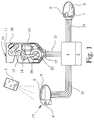
- Fig. 1 shows a largely electronically controlled locking and central locking system for a motor vehicle. This is shown in sections.
- Control signals are transmitted from a portable transmitter module 3 carried by the driver (electronic key / smart card), which strike a receiver 4 on the outer door handle 5 on the motor vehicle body.
- the receiver 4 is connected to the control electronics 1.
- the outer door handle 5 with its recessed grip 6 only transmits an electrical control signal to the control electronics 1. It therefore represents a mechanical or electrical actuation handle. Mechanical connections are no longer provided.
- only electrical signals are generated from the inside door handle 7 via corresponding microswitches and transmitted to the control electronics 1, in the exemplary embodiment shown an opening signal from the recessed grip 8 and possibly also an unlocking signal and a fuse signal from the fuse button 9.
- the actual motor vehicle door lock 10 which can also be a lock on a tailgate or tailgate, has very few mechanical parts.
- the outer housing 11 has an inlet slot for a locking block, not shown.
- a lock latch arranged in the housing 11 and designed as a rotary latch 13 moves in the inlet slot. This is held in the closed position by a pawl 14 arranged in the housing 11.
- a pawl switch 16 which represents the position of the pawl 14, is initially provided as the microswitch.
- a handle switch 17 which represents the position of the actuating handle or its state of influence.
- a further microswitch is provided which, as a rotary latch switch 20, senses the position of the rotary latch 13.
- An electrical connection device 19 for the electrical connections is arranged on the outside of the housing 11. It can be provided that all the conductor tracks to the electrical connection device 19 are cast into the material of the housing 11, which will usually be plastic, as is known per se from the prior art. In any case, the electrical connection device 19 can be connected to the control electronics 1 via a corresponding electrical connecting cable 21 or a corresponding bus system. It is also possible without further ado to assign decentralized control electronics 1 to each of the motor vehicle door locks 10 of the motor vehicle locking system and to superordinate central control electronics again.
- Fig. 1 also makes clear that the pawl switch 16 or the position of a pawl 14 lifting the cam 22 or the like. And not the position of the pawl 14 itself scans. The pawl 14 can thus, for example when the rotary latch is still open, still be lifted by resting on the one rotary latch leg while the cam 22 or the like has already continued to run.
- the position of the cam 22 is determined by the pawl switch 16 in the preferred embodiment, so that the actuation of the pawl switch 16 after the initial lifting of the pawl 14 is independent of the actual position of the pawl 14.
- control takes place within the scope of the method according to the invention such that the drive 15 always returns to its ready position after the initial control and that actuation of the actuation handle 5 does not trigger a switching function below a minimum time t min .
- the minimum time t min is approximately 15 to 40 ms, preferably approximately 25 ms.
- any actuation of the actuation handle 5 below the minimum time t min can not trigger a switching function.
- the illustrated and, to this extent, preferred exemplary embodiment shows, however, that only actuating the actuating handle 5 in a direction below the minimum time t min does not trigger a switching function, in particular only the first actuation. Then the minimum time t min does not occur in places where you no longer need it.
- the pawl switch 16 in the illustrated embodiment does not sense the actual position of the pawl 14 itself, but rather the position of the cam 22, the pawl switch 16 can itself be used for the switching signal when the ready position is reached.
- the illustrated embodiment shows that a rotary latch switch 20 exists. This is not mandatory, the rotary latch switch 20 is optional.
- the illustrated embodiment also shows in broken lines that, under special circumstances, an additional standby switch 18 can be provided, which is switched when the drive 15 is in the standby or idle position. Reference may be made to the above explanations.
- the illustrated embodiment makes it clear, without being restrictive, that when the actuating handle 5 is not actuated, the handle switch 17 connects the connections A5, A6, but when the actuating handle 5 is actuated, the connections A5 and A7.
- connections A1, A2 (and possibly A4) are scanned with the possibilities of the signal “ “ and “ “”, connection A3 is energized with” + “or a rest position with” ".
- Fig. 3 shows the course of the signals at the various connections or switches. Above you can see the curve of the handle switch 17 first with the actuation handle 5 not actuated with the connection A5-A6, then with the actuation handle actuated with the connection A5-A7. Below you can see the course of the Signals at connection A2. This shows the course of the signal at connection A3 for energizing the drive 15.
- Port A3 is set to + after the minimum time t min has elapsed.
- A2 is queried and initially shows the signal .
- the signal at A2 jumps up .
- the control logic 23 A3 switched and the drive 15 thus stopped. If the actuating handle 5 is now released, the handle switch 17 switches from A5-A7 to A5-A6.
- This switching measure triggers a switching function for A3 (possibly also after the minimum time t min has elapsed again ), where from switched to + and the drive 15 is energized again.
- the drive 15 continues to run until the pawl switch 16 switches from on (or the other way around).
- the control logic 23 recognizes this change when the ready position is reached and immediately switches A3 from + to and the drive 15 stops.
- pawl switch 16 Since only the pawl switch 16 is initially provided in the illustrated embodiment, it is imperative that it only scans the position of a cam 22, not the position of the pawl 14 itself. The switching of the pawl switch 16 can thereby be defined as reaching the ready position of the drive 15, regardless of the actual position of the pawl 14.
- pawl switch 16 scans the pawl 14 directly, it would not be actuated if the pawl 14 is held mechanically in the open position. In this case, an additional standby switch 18 is required, as shown in broken lines in FIG. 2, in order to then switch off the drive 15 in the standby position.
- Fig. 4 shows the course of the signals in the circuit arrangement explained above in the event that the actuating handle 5 is actuated only briefly, the handle switch 17 is therefore operated with a time which is greater than t min , but is shorter than that required for opening. It can be seen that the circuit at A2 remains ineffective for the signal at A3, since the signal from the handle switch 17 has previously occurred again.
- the evaluation of the signals at the connection A1 to the rotary latch switch 20 by the control logic 23 makes it possible to determine the actual opening position of the motor vehicle door lock or the like in this circuit arrangement. It can thus be determined whether the motor vehicle door lock has actually opened mechanically when the opening function is run or whether it has not been able to open due to external influences (freezing of the seal, snow load, sticking of the seal or the like).
- the query of the rotary latch switch 20 thus allows the so-called "snow load function" to be integrated into the circuit arrangement.
- control logic 23 is a direct component of the motor vehicle door lock, ie delay times in the control are negligible.
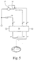
- the exemplary embodiment shown in FIG. 5, takes into account a partially decentralized, automatic control that allows time delays, for example, to be taken into account by a central control logic 23.
- the circuit arrangement from FIG. 5 initially has various connections in common with the circuit arrangement from FIG. 2, so that further explanations are not necessary.
- the circuit arrangement from FIG. 5 differs from the circuit arrangement from FIG. 2 in that the pawl switch 16 is designed as a changeover switch which lies between the " + " connection of the drive 15 and the connections A3 and A4 to the control logic 23.
- the drive 15 is connected to either A3 or A4.
- the pawl switch 16 is not controlled by the control logic 23 in the exemplary embodiment shown, but directly by the drive 15. That these switches are somehow associated with + and must be connected, is obvious, is not shown in Fig. 5.
- the pawl switch 16 is actuated by an actuating element on the drive 15 itself when the cam 22 or the like is firmly coupled to the drive 15 or the like.
- a cam control can also be used in a classic manner separately from the drive 15 to actuate the pawl switch 16.
Landscapes
- Engineering & Computer Science (AREA)
- Computer Networks & Wireless Communication (AREA)
- Physics & Mathematics (AREA)
- General Physics & Mathematics (AREA)
- Lock And Its Accessories (AREA)
Applications Claiming Priority (6)
| Application Number | Priority Date | Filing Date | Title |
|---|---|---|---|
| DE19620256 | 1996-05-21 | ||
| DE19620256 | 1996-05-21 | ||
| DE19623165 | 1996-05-30 | ||
| DE19623165 | 1996-05-30 | ||
| DE19632915 | 1996-08-16 | ||
| DE19632915A DE19632915A1 (de) | 1996-05-21 | 1996-08-16 | Verfahren zur Ansteuerung eines elektrisch betätigten Kraftfahrzeug-Türschlosses o. dgl. |
Publications (2)
| Publication Number | Publication Date |
|---|---|
| EP0808977A1 true EP0808977A1 (fr) | 1997-11-26 |
| EP0808977B1 EP0808977B1 (fr) | 2000-08-16 |
Family
ID=27216251
Family Applications (1)
| Application Number | Title | Priority Date | Filing Date |
|---|---|---|---|
| EP19970107899 Expired - Lifetime EP0808977B1 (fr) | 1996-05-21 | 1997-05-15 | Méthode pour le contrôle d'une serrure pour portière de véhicule automobile actionnée de façon électrique |
Country Status (4)
| Country | Link |
|---|---|
| US (1) | US5901991A (fr) |
| EP (1) | EP0808977B1 (fr) |
| JP (1) | JPH1046893A (fr) |
| BR (1) | BR9703301A (fr) |
Cited By (15)
| Publication number | Priority date | Publication date | Assignee | Title |
|---|---|---|---|---|
| WO1999007968A1 (fr) * | 1997-08-06 | 1999-02-18 | Meritor Light Vehicle Systems (Uk) Ltd. | Mecanisme de porte de vehicule |
| WO1999031339A1 (fr) * | 1997-12-15 | 1999-06-24 | Robert Bosch Gmbh | Dispositif d'actionnement pour une serrure electrique d'une portiere de vehicule a moteur |
| WO1999041474A1 (fr) * | 1998-02-11 | 1999-08-19 | Rover Group Limited | Systeme de fermeture d'une porte de vehicule a moteur |
| FR2775016A1 (fr) * | 1998-02-19 | 1999-08-20 | Valeo Systemes De Fermetures | Perfectionnement aux serrures electriques d'ouvrant de vehic ule automobile avec fonctionnement en deux phases |
| FR2775718A1 (fr) * | 1998-03-06 | 1999-09-10 | Valeo Systemes De Fermetures | Serrure a commande electrique pour portiere de vehicule comportant une pile de secours |
| FR2778940A1 (fr) * | 1998-05-19 | 1999-11-26 | Valeo Securite Habitacle | Serrure de porte de vehicule automobile a decondamnation electrique et ouverture electrique |
| EP0978610A1 (fr) * | 1998-08-05 | 2000-02-09 | Valeo Securite Habitacle | Serrure électrique perfectionnée pour ouvrant de véhicule automobile |
| WO2000019045A1 (fr) * | 1998-09-30 | 2000-04-06 | Robert Bosch Gmbh | Serrure de portiere d'automobile ou similaire munie d'une commande de moteur electronique |
| EP1035281A1 (fr) * | 1999-03-12 | 2000-09-13 | ATOMA ROLTRA S.p.A. | Système de verrouillage pour porte de véhicule automobile |
| EP0979914A3 (fr) * | 1998-08-11 | 2003-01-29 | Siemens Aktiengesellschaft | Dispositif de verrouillage |
| DE10007274B4 (de) * | 1999-03-04 | 2006-07-27 | Ford Global Technologies, Dearborn | Elektrisches Verschluss- und Verriegelungssystem bei einem Kraftfahrzeug |
| WO2013127382A3 (fr) * | 2012-02-28 | 2014-10-23 | Kiekert Aktiengesellschaft | Fermeture de portière de véhicule à moteur |
| WO2015033201A1 (fr) * | 2013-09-04 | 2015-03-12 | Kiekert Ag | Porte de véhicule à moteur dotée d'une poignée et d'une serrure |
| FR3014472A1 (fr) * | 2013-12-10 | 2015-06-12 | Inteva Products Llc | |
| CN109790731A (zh) * | 2016-07-22 | 2019-05-21 | 标致雪铁龙汽车股份有限公司 | 机动车辆的打开件的打开控制系统 |
Families Citing this family (74)
| Publication number | Priority date | Publication date | Assignee | Title |
|---|---|---|---|---|
| US6102454A (en) * | 1997-09-15 | 2000-08-15 | Robert Bosch Gmbh | Motor vehicle door lock arrangement |
| FR2778196B1 (fr) * | 1998-04-30 | 2000-06-23 | Valeo Securite Habitacle | Serrure de porte de vehicule automobile |
| DE19828202A1 (de) * | 1998-06-25 | 1999-12-30 | Mannesmann Vdo Ag | Schließeinrichtung für ein bewegliches Element, insbesondere für eine Tür eines Fahrzeuges |
| GB2340868B (en) * | 1998-08-19 | 2002-04-24 | Meritor Light Vehicle Sys Ltd | Vehicle door latch |
| DE19841729B4 (de) * | 1998-09-12 | 2006-07-06 | Siemens Ag | Griffanordnung für ein bewegliches Karosserieteil |
| US6786070B1 (en) | 1999-03-05 | 2004-09-07 | Sirattec Security Corporation | Latch apparatus and method |
| CA2299921A1 (fr) * | 1999-03-05 | 2000-09-05 | Strattec Security Corporation | Methode et appareil de verrouillage modulaire |
| US6463773B1 (en) * | 1999-03-05 | 2002-10-15 | Strattec Security Corporation | Electronic latch apparatus and method |
| US6256932B1 (en) * | 1999-06-29 | 2001-07-10 | Daimlerchrysler Corporation | Electronically-controlled vehicle door system |
| WO2001040606A1 (fr) * | 1999-11-29 | 2001-06-07 | Robert Bosch Gmbh | Systeme de verrouillage de portes d'automobile |
| FR2801623B1 (fr) * | 1999-11-29 | 2002-01-04 | Valeo Securite Habitacle | Ouvrant de vehicule automobile avec serrure a condamnation/decondamnation electrique apte a s'ouvrir a retardement |
| JP3773731B2 (ja) * | 1999-12-24 | 2006-05-10 | 株式会社大井製作所 | ドアロック装置 |
| GB0011991D0 (en) * | 2000-05-19 | 2000-07-05 | Meritor Light Vehicle Sys Ltd | Latch assembly and vehicle including such a latch assembly |
| JP4358416B2 (ja) * | 2000-08-24 | 2009-11-04 | アスモ株式会社 | 扉体の施解錠装置 |
| US6575505B1 (en) | 2000-10-25 | 2003-06-10 | Strattec Security Corporation | Latch apparatus and method |
| DE10100010B4 (de) * | 2001-01-02 | 2005-05-12 | Brose Schließsysteme GmbH & Co.KG | Kraftfahrzeug-Türschloß, ausgeführt als Elektroschloß, sowie Verfahren zur Montage eines als Elektroschloß ausgeführten Kraftfahrzeug-Türschlosses |
| DE10164829B4 (de) * | 2001-01-02 | 2006-07-13 | Brose Schließsysteme GmbH & Co.KG | Kraftfahrzeug-Türschloss, ausgeführt als Elektroschloss |
| US6776442B2 (en) | 2001-01-09 | 2004-08-17 | Strattec Security Corporation | Latch apparatus and method |
| JP4132723B2 (ja) * | 2001-05-15 | 2008-08-13 | 株式会社大井製作所 | 車両用ドアロック装置 |
| GB0113542D0 (en) * | 2001-06-05 | 2001-07-25 | Meritor Light Vehicle Sys Ltd | A mechanism |
| US8818871B2 (en) * | 2001-06-21 | 2014-08-26 | Thomson Licensing | Method and system for electronic purchases using an intelligent data carrier medium, electronic coupon system, and interactive TV infrastructure |
| FR2826998B1 (fr) * | 2001-07-05 | 2004-01-30 | Philippe Louvel | Poignee de porte equipee d'un portillon retractable automatique |
| GB0122634D0 (en) * | 2001-09-20 | 2001-11-14 | Meritor Light Vehicle Sys Ltd | Door release and engagement mechanism |
| US6779372B2 (en) * | 2001-10-16 | 2004-08-24 | Robert Bosch Gmbh | Motor vehicle door lock with a lock unit and a control unit which are separate from one another |
| JP3975740B2 (ja) * | 2001-12-14 | 2007-09-12 | アイシン精機株式会社 | 車両ドア制御装置 |
| JP4161664B2 (ja) * | 2002-09-27 | 2008-10-08 | アイシン精機株式会社 | 車両用ドアハンドル装置 |
| US6988749B2 (en) * | 2003-06-09 | 2006-01-24 | Shiroki Corporation | Door locking system for motor vehicle |
| DE10326416A1 (de) * | 2003-06-12 | 2004-12-30 | Hella Kgaa Hueck & Co. | Verriegelungsverfahren und Verriegelungsvorrichtung für ein bewegliches Element, insbesondere eine Klappe |
| DE10331080A1 (de) * | 2003-07-09 | 2005-01-27 | Kiekert Ag | Kraftfahrzeugtürverschluss |
| US7364211B2 (en) * | 2003-11-13 | 2008-04-29 | Intier Automotive Closures Inc. | Vehicle lock controlled by a shape memory alloy actuator |
| US7261335B2 (en) * | 2003-11-14 | 2007-08-28 | Intier Automotive Closures Inc. | Power release side door latch with emergency release system |
| DE10360422A1 (de) * | 2003-12-19 | 2005-07-21 | Brose Schließsysteme GmbH & Co.KG | Kraftfahrzeug |
| DE102004042966A1 (de) * | 2004-09-02 | 2006-03-09 | Brose Schließsysteme GmbH & Co.KG | Kraftfahrzeugschloß |
| US20080054649A1 (en) * | 2004-09-02 | 2008-03-06 | Matsushita Electric Industrial Co., Ltd. | Door Opening/Closing Device, Keyless Entry Device with the Door Opening/Closing Device, Vehicle Door or Building Door Carrying the Keyless Entry Device |
| JP4426417B2 (ja) * | 2004-10-08 | 2010-03-03 | 三井金属鉱業株式会社 | ドアラッチ装置 |
| CA2533757A1 (fr) * | 2005-01-24 | 2006-07-24 | Magna Closures Inc. | Mecanisme de verrouillage pour poignees exterieures de portes de vehicule |
| US7501595B2 (en) * | 2005-10-06 | 2009-03-10 | Strattec Security Corporation | Self-compensating motion detector |
| JP4734212B2 (ja) | 2006-10-17 | 2011-07-27 | 三井金属アクト株式会社 | ラッチ装置 |
| US20080224482A1 (en) * | 2007-02-15 | 2008-09-18 | Cumbo Francesco | Electrical Door Latch |
| DE202008010423U1 (de) * | 2008-08-05 | 2009-12-17 | Kiekert Ag | Kraftfahrzeugtürverschluss mit einer Schaltungsanordnung |
| US8573657B2 (en) * | 2009-03-12 | 2013-11-05 | Ford Global Technologies, Llc | Latch mechanism |
| US9260882B2 (en) | 2009-03-12 | 2016-02-16 | Ford Global Technologies, Llc | Universal global latch system |
| JP5554401B2 (ja) | 2009-04-27 | 2014-07-23 | アキュライド インターナショナル,インコーポレイテッド | 引出しスライド及び錠止機構 |
| US9080355B2 (en) * | 2009-12-18 | 2015-07-14 | Brose Schliesssysteme Gmbh & Co. Kg | Circuit and method for preventing inadvertent opening of a vehicle door |
| US8689591B2 (en) * | 2009-12-23 | 2014-04-08 | 9G Products, Inc. | Personal property safe |
| US9777512B2 (en) * | 2011-04-14 | 2017-10-03 | Janus International Group, Llc | Locking apparatus for a rollup door or other movable object |
| USD665244S1 (en) | 2011-09-13 | 2012-08-14 | The Eastern Company | Rotary latch |
| US9551166B2 (en) | 2011-11-02 | 2017-01-24 | Ford Global Technologies, Llc | Electronic interior door release system |
| CA2798465C (fr) * | 2011-12-09 | 2015-06-30 | Messier-Bugatti-Dowty | Boitier d'accrochage a actionneur a came d'encombrement reduit |
| DE102012207441A1 (de) * | 2012-05-04 | 2013-11-07 | Kiekert Ag | Schloss für eine Klappe oder Tür |
| GB2518789B (en) | 2012-07-18 | 2020-05-13 | Accuride Int Inc | Drawer slide and electronically actuated locking mechanism |
| USD712233S1 (en) * | 2013-01-14 | 2014-09-02 | Impact Weapons Components, LLC | Sling latch |
| US9416565B2 (en) | 2013-11-21 | 2016-08-16 | Ford Global Technologies, Llc | Piezo based energy harvesting for e-latch systems |
| JP5972919B2 (ja) * | 2014-02-04 | 2016-08-17 | 本田技研工業株式会社 | 車両のドア装置 |
| US9834964B2 (en) | 2014-05-13 | 2017-12-05 | Ford Global Technologies, Llc | Powered vehicle door latch and exterior handle with sensor |
| US9903142B2 (en) | 2014-05-13 | 2018-02-27 | Ford Global Technologies, Llc | Vehicle door handle and powered latch system |
| US10323442B2 (en) | 2014-05-13 | 2019-06-18 | Ford Global Technologies, Llc | Electronic safe door unlatching operations |
| US10119308B2 (en) | 2014-05-13 | 2018-11-06 | Ford Global Technologies, Llc | Powered latch system for vehicle doors and control system therefor |
| US10273725B2 (en) | 2014-05-13 | 2019-04-30 | Ford Global Technologies, Llc | Customer coaching method for location of E-latch backup handles |
| US9909344B2 (en) | 2014-08-26 | 2018-03-06 | Ford Global Technologies, Llc | Keyless vehicle door latch system with powered backup unlock feature |
| US10563437B2 (en) * | 2014-09-18 | 2020-02-18 | Huf Hülsbeck & Fürst Gmbh & Co. Kg | Flush comfort handle |
| US20160138301A1 (en) * | 2014-11-14 | 2016-05-19 | The Boeing Company | Self-contained electronic stowage bin system |
| US9725069B2 (en) | 2015-10-12 | 2017-08-08 | Ford Global Technologies, Llc | Keyless vehicle systems |
| US10550610B2 (en) | 2016-06-22 | 2020-02-04 | Ford Global Technologies, Llc | Inside override emergency handle for door release |
| US10227810B2 (en) | 2016-08-03 | 2019-03-12 | Ford Global Technologies, Llc | Priority driven power side door open/close operations |
| US10087671B2 (en) | 2016-08-04 | 2018-10-02 | Ford Global Technologies, Llc | Powered driven door presenter for vehicle doors |
| US10329823B2 (en) | 2016-08-24 | 2019-06-25 | Ford Global Technologies, Llc | Anti-pinch control system for powered vehicle doors |
| US10458171B2 (en) | 2016-09-19 | 2019-10-29 | Ford Global Technologies, Llc | Anti-pinch logic for door opening actuator |
| US10604970B2 (en) | 2017-05-04 | 2020-03-31 | Ford Global Technologies, Llc | Method to detect end-of-life in latches |
| US11173968B2 (en) * | 2018-05-17 | 2021-11-16 | Kiekert Ag | Motor vehicle door latch |
| US10907386B2 (en) | 2018-06-07 | 2021-02-02 | Ford Global Technologies, Llc | Side door pushbutton releases |
| KR102815687B1 (ko) * | 2020-07-14 | 2025-06-02 | 현대자동차주식회사 | 차량 및 차량의 테일게이트 잠금 장치 |
| DE102021102766A1 (de) | 2021-02-05 | 2022-08-11 | Brose Schließsysteme GmbH & Co. Kommanditgesellschaft | Kraftfahrzeugschlossanordnung für eine Klappe eines Kraftfahrzeugs |
| DE102022133481A1 (de) * | 2022-12-15 | 2024-06-20 | Brose Fahrzeugteile Se & Co. Kommanditgesellschaft, Bamberg | Kraftfahrzeugschließsystem |
Citations (4)
| Publication number | Priority date | Publication date | Assignee | Title |
|---|---|---|---|---|
| DE3242527A1 (de) * | 1982-11-18 | 1984-05-24 | Neiman GmbH, 5657 Haan | Elektroschloss |
| DE3626441C1 (en) * | 1986-08-05 | 1987-09-24 | Bayerische Motoren Werke Ag | Motor-vehicle door lock |
| US4976477A (en) * | 1988-09-30 | 1990-12-11 | Fuji Jukogyo Kabushiki Kaisha | Device for locking trunk lid of motor vehicle |
| EP0589158A1 (fr) * | 1992-08-25 | 1994-03-30 | Bayerische Motoren Werke Aktiengesellschaft | Serrure commandable à distance, en particulier pour des portières de véhicule automobile |
Family Cites Families (7)
| Publication number | Priority date | Publication date | Assignee | Title |
|---|---|---|---|---|
| FR2542793B1 (fr) * | 1983-03-14 | 1985-07-19 | Mecanismes Comp Ind De | Serrure a ouverture electrique, notamment pour portieres de vehicules automobiles |
| US4667990A (en) * | 1984-07-16 | 1987-05-26 | Quantz Norman G | Electrically actuated lock mechanism |
| GB2206638B (en) * | 1987-05-22 | 1991-03-20 | Pickersgill Kaye Ltd | Electromechanical lock |
| DE3821840C1 (fr) * | 1988-06-29 | 1989-10-19 | Heraeus Sepatech Gmbh, 3360 Osterode, De | |
| US4995651A (en) * | 1989-12-01 | 1991-02-26 | The Cookson Company | Release mechanism and method |
| JP2657877B2 (ja) * | 1992-11-30 | 1997-09-30 | 株式会社大井製作所 | 自動車用ドアロックの制御装置 |
| JP2948491B2 (ja) * | 1994-11-21 | 1999-09-13 | 三井金属鉱業株式会社 | 車両ロック装置のアクチュエータ |
-
1997
- 1997-05-15 EP EP19970107899 patent/EP0808977B1/fr not_active Expired - Lifetime
- 1997-05-21 US US08/861,014 patent/US5901991A/en not_active Expired - Fee Related
- 1997-05-21 BR BR9703301A patent/BR9703301A/pt active Search and Examination
- 1997-05-21 JP JP13019197A patent/JPH1046893A/ja active Pending
Patent Citations (4)
| Publication number | Priority date | Publication date | Assignee | Title |
|---|---|---|---|---|
| DE3242527A1 (de) * | 1982-11-18 | 1984-05-24 | Neiman GmbH, 5657 Haan | Elektroschloss |
| DE3626441C1 (en) * | 1986-08-05 | 1987-09-24 | Bayerische Motoren Werke Ag | Motor-vehicle door lock |
| US4976477A (en) * | 1988-09-30 | 1990-12-11 | Fuji Jukogyo Kabushiki Kaisha | Device for locking trunk lid of motor vehicle |
| EP0589158A1 (fr) * | 1992-08-25 | 1994-03-30 | Bayerische Motoren Werke Aktiengesellschaft | Serrure commandable à distance, en particulier pour des portières de véhicule automobile |
Cited By (18)
| Publication number | Priority date | Publication date | Assignee | Title |
|---|---|---|---|---|
| WO1999007968A1 (fr) * | 1997-08-06 | 1999-02-18 | Meritor Light Vehicle Systems (Uk) Ltd. | Mecanisme de porte de vehicule |
| WO1999031339A1 (fr) * | 1997-12-15 | 1999-06-24 | Robert Bosch Gmbh | Dispositif d'actionnement pour une serrure electrique d'une portiere de vehicule a moteur |
| WO1999041474A1 (fr) * | 1998-02-11 | 1999-08-19 | Rover Group Limited | Systeme de fermeture d'une porte de vehicule a moteur |
| FR2775016A1 (fr) * | 1998-02-19 | 1999-08-20 | Valeo Systemes De Fermetures | Perfectionnement aux serrures electriques d'ouvrant de vehic ule automobile avec fonctionnement en deux phases |
| FR2775718A1 (fr) * | 1998-03-06 | 1999-09-10 | Valeo Systemes De Fermetures | Serrure a commande electrique pour portiere de vehicule comportant une pile de secours |
| FR2778940A1 (fr) * | 1998-05-19 | 1999-11-26 | Valeo Securite Habitacle | Serrure de porte de vehicule automobile a decondamnation electrique et ouverture electrique |
| EP0978610A1 (fr) * | 1998-08-05 | 2000-02-09 | Valeo Securite Habitacle | Serrure électrique perfectionnée pour ouvrant de véhicule automobile |
| FR2782111A1 (fr) * | 1998-08-05 | 2000-02-11 | Valeo Securite Habitacle | Serrure electrique perfectionnee pour ouvrant de vehicule automobile |
| US6109671A (en) * | 1998-08-05 | 2000-08-29 | Valeo Securite Habitacle | Electric lock for a motor vehicle opening leaf |
| EP0979914A3 (fr) * | 1998-08-11 | 2003-01-29 | Siemens Aktiengesellschaft | Dispositif de verrouillage |
| WO2000019045A1 (fr) * | 1998-09-30 | 2000-04-06 | Robert Bosch Gmbh | Serrure de portiere d'automobile ou similaire munie d'une commande de moteur electronique |
| DE10007274B4 (de) * | 1999-03-04 | 2006-07-27 | Ford Global Technologies, Dearborn | Elektrisches Verschluss- und Verriegelungssystem bei einem Kraftfahrzeug |
| EP1035281A1 (fr) * | 1999-03-12 | 2000-09-13 | ATOMA ROLTRA S.p.A. | Système de verrouillage pour porte de véhicule automobile |
| WO2013127382A3 (fr) * | 2012-02-28 | 2014-10-23 | Kiekert Aktiengesellschaft | Fermeture de portière de véhicule à moteur |
| WO2015033201A1 (fr) * | 2013-09-04 | 2015-03-12 | Kiekert Ag | Porte de véhicule à moteur dotée d'une poignée et d'une serrure |
| FR3014472A1 (fr) * | 2013-12-10 | 2015-06-12 | Inteva Products Llc | |
| CN109790731A (zh) * | 2016-07-22 | 2019-05-21 | 标致雪铁龙汽车股份有限公司 | 机动车辆的打开件的打开控制系统 |
| CN109790731B (zh) * | 2016-07-22 | 2021-01-12 | 标致雪铁龙汽车股份有限公司 | 机动车辆的打开件的打开控制系统 |
Also Published As
| Publication number | Publication date |
|---|---|
| BR9703301A (pt) | 1998-07-07 |
| US5901991A (en) | 1999-05-11 |
| JPH1046893A (ja) | 1998-02-17 |
| EP0808977B1 (fr) | 2000-08-16 |
Similar Documents
| Publication | Publication Date | Title |
|---|---|---|
| EP0808977B1 (fr) | Méthode pour le contrôle d'une serrure pour portière de véhicule automobile actionnée de façon électrique | |
| EP1048808B1 (fr) | Serrure de porte de véhicule avec assistance électrique pour l'ouverture et la fermeture | |
| DE19619849C2 (de) | Schloß, insbesondere für Kraftfahrzeugtüren | |
| DE19706393B4 (de) | Kraftfahrzeug mit elektronischer Steuereinrichtung für die Betätigung der Kraftfahrzeugtür mit Kraftfahrzeugtürverschluß | |
| DE19614122B4 (de) | Kraftfahrzeug-Klappenschloß oder -Türschloß | |
| DE3636828C2 (fr) | ||
| EP1304433A1 (fr) | Serrure de la porte d'automobile avec une unité de fermeture et une unité de commande separarée l'un de l'autre | |
| EP1045093B1 (fr) | Serrure pour une porte d'automobile ou similaire | |
| DE69509317T2 (de) | Anordnung bestehend aus einem elektrischen Kraftfahrzeug-Türschloss und aus seinen zugehörigen Steuerungs- und Versorgungsmitteln | |
| DE19711563A1 (de) | Schaltungsanordnung zur Steuerung eines elektrisch betätigten Kraftfahrzeug-Türschlosses o. dgl. | |
| DE19710834C2 (de) | Vorrichtung und Verfahren zum Betätigen eines Sperrelements | |
| EP3303741A1 (fr) | Fermeture de porte d'un véhicule à moteur | |
| EP1083282A2 (fr) | Système de verrouilage de porte de véhicule avec fonction d'accès sans clef et déverrouillage rapide | |
| DE102015108739A1 (de) | Verfahren zur Steuerung eines Kraftfahrzeugtürverschlusses | |
| DE19632915A1 (de) | Verfahren zur Ansteuerung eines elektrisch betätigten Kraftfahrzeug-Türschlosses o. dgl. | |
| EP1283934B1 (fr) | Systeme de fermeture de portes automobile avec deverrouillage rapide | |
| DE19924458B4 (de) | Kraftfahrzeug-Türschließeinrichtung | |
| DE4218798C2 (de) | Schließanlage für Verschlüsse eines Fahrzeuges | |
| DE19924447C2 (de) | Kraftfahrzeug-Türschloß, -Haubenschloß oder -Klappenschloß | |
| DE2735999C2 (de) | Zentralverriegelungseinrichtung, insbesondere für die Türen von Kraftfahrzeugen | |
| DE10151022A1 (de) | Kraftfahrzeug-Türschloß mit voneinander getrennter Schließeinheit und Steuereinheit | |
| DE19754216A1 (de) | Kraftfahrzeug-Türschließeinrichtung | |
| DE10319744A1 (de) | Kraftfahrzeugtürschloß mit elektromotorischem Öffnungsantrieb | |
| DE19847079A1 (de) | Elektrisches Schloß für Kraftfahrzeuge | |
| EP3274530B1 (fr) | Dispositif d'actionnement électrique avec alimentation électrique de secours pour une serrure électrique de véhicule à moteur et procédé associé |
Legal Events
| Date | Code | Title | Description |
|---|---|---|---|
| PUAI | Public reference made under article 153(3) epc to a published international application that has entered the european phase |
Free format text: ORIGINAL CODE: 0009012 |
|
| AK | Designated contracting states |
Kind code of ref document: A1 Designated state(s): DE FR GB IT |
|
| 17P | Request for examination filed |
Effective date: 19980526 |
|
| 17Q | First examination report despatched |
Effective date: 19981124 |
|
| GRAG | Despatch of communication of intention to grant |
Free format text: ORIGINAL CODE: EPIDOS AGRA |
|
| 17Q | First examination report despatched |
Effective date: 19981124 |
|
| GRAG | Despatch of communication of intention to grant |
Free format text: ORIGINAL CODE: EPIDOS AGRA |
|
| GRAH | Despatch of communication of intention to grant a patent |
Free format text: ORIGINAL CODE: EPIDOS IGRA |
|
| GRAH | Despatch of communication of intention to grant a patent |
Free format text: ORIGINAL CODE: EPIDOS IGRA |
|
| GRAA | (expected) grant |
Free format text: ORIGINAL CODE: 0009210 |
|
| AK | Designated contracting states |
Kind code of ref document: B1 Designated state(s): DE FR GB IT |
|
| REF | Corresponds to: |
Ref document number: 59702180 Country of ref document: DE Date of ref document: 20000921 |
|
| ITF | It: translation for a ep patent filed | ||
| GBT | Gb: translation of ep patent filed (gb section 77(6)(a)/1977) |
Effective date: 20001018 |
|
| ET | Fr: translation filed | ||
| PLBE | No opposition filed within time limit |
Free format text: ORIGINAL CODE: 0009261 |
|
| STAA | Information on the status of an ep patent application or granted ep patent |
Free format text: STATUS: NO OPPOSITION FILED WITHIN TIME LIMIT |
|
| 26N | No opposition filed | ||
| REG | Reference to a national code |
Ref country code: GB Ref legal event code: IF02 |
|
| PGFP | Annual fee paid to national office [announced via postgrant information from national office to epo] |
Ref country code: GB Payment date: 20060510 Year of fee payment: 10 |
|
| PGFP | Annual fee paid to national office [announced via postgrant information from national office to epo] |
Ref country code: FR Payment date: 20060515 Year of fee payment: 10 |
|
| PGFP | Annual fee paid to national office [announced via postgrant information from national office to epo] |
Ref country code: DE Payment date: 20070531 Year of fee payment: 11 |
|
| PGFP | Annual fee paid to national office [announced via postgrant information from national office to epo] |
Ref country code: IT Payment date: 20070507 Year of fee payment: 11 |
|
| GBPC | Gb: european patent ceased through non-payment of renewal fee |
Effective date: 20070515 |
|
| REG | Reference to a national code |
Ref country code: FR Ref legal event code: ST Effective date: 20080131 |
|
| PG25 | Lapsed in a contracting state [announced via postgrant information from national office to epo] |
Ref country code: GB Free format text: LAPSE BECAUSE OF NON-PAYMENT OF DUE FEES Effective date: 20070515 |
|
| PG25 | Lapsed in a contracting state [announced via postgrant information from national office to epo] |
Ref country code: FR Free format text: LAPSE BECAUSE OF NON-PAYMENT OF DUE FEES Effective date: 20070531 |
|
| PG25 | Lapsed in a contracting state [announced via postgrant information from national office to epo] |
Ref country code: DE Free format text: LAPSE BECAUSE OF NON-PAYMENT OF DUE FEES Effective date: 20081202 |
|
| PG25 | Lapsed in a contracting state [announced via postgrant information from national office to epo] |
Ref country code: IT Free format text: LAPSE BECAUSE OF NON-PAYMENT OF DUE FEES Effective date: 20080515 |