EP0809021A2 - Méthode et dispositif de commande de préchauffage des bougies de réchauffage d'un moteur diesel - Google Patents
Méthode et dispositif de commande de préchauffage des bougies de réchauffage d'un moteur diesel Download PDFInfo
- Publication number
- EP0809021A2 EP0809021A2 EP97108081A EP97108081A EP0809021A2 EP 0809021 A2 EP0809021 A2 EP 0809021A2 EP 97108081 A EP97108081 A EP 97108081A EP 97108081 A EP97108081 A EP 97108081A EP 0809021 A2 EP0809021 A2 EP 0809021A2
- Authority
- EP
- European Patent Office
- Prior art keywords
- glow plug
- temperature
- glow
- filament
- heating
- Prior art date
- Legal status (The legal status is an assumption and is not a legal conclusion. Google has not performed a legal analysis and makes no representation as to the accuracy of the status listed.)
- Granted
Links
- 238000000034 method Methods 0.000 title claims abstract description 37
- 238000010438 heat treatment Methods 0.000 claims abstract description 91
- 230000001276 controlling effect Effects 0.000 claims description 9
- 230000001105 regulatory effect Effects 0.000 claims description 8
- 230000005540 biological transmission Effects 0.000 claims description 2
- 238000011156 evaluation Methods 0.000 claims 1
- 238000009434 installation Methods 0.000 claims 1
- 238000010586 diagram Methods 0.000 description 10
- 239000000446 fuel Substances 0.000 description 4
- 238000005259 measurement Methods 0.000 description 4
- 230000001681 protective effect Effects 0.000 description 3
- 238000000137 annealing Methods 0.000 description 2
- 238000012360 testing method Methods 0.000 description 2
- 238000013459 approach Methods 0.000 description 1
- 238000002485 combustion reaction Methods 0.000 description 1
- 238000013461 design Methods 0.000 description 1
- 230000002349 favourable effect Effects 0.000 description 1
- 238000012423 maintenance Methods 0.000 description 1
- 238000005457 optimization Methods 0.000 description 1
Images


Classifications
-
- F—MECHANICAL ENGINEERING; LIGHTING; HEATING; WEAPONS; BLASTING
- F02—COMBUSTION ENGINES; HOT-GAS OR COMBUSTION-PRODUCT ENGINE PLANTS
- F02P—IGNITION, OTHER THAN COMPRESSION IGNITION, FOR INTERNAL-COMBUSTION ENGINES; TESTING OF IGNITION TIMING IN COMPRESSION-IGNITION ENGINES
- F02P19/00—Incandescent ignition, e.g. during starting of internal combustion engines; Combination of incandescent and spark ignition
- F02P19/02—Incandescent ignition, e.g. during starting of internal combustion engines; Combination of incandescent and spark ignition electric, e.g. layout of circuits of apparatus having glowing plugs
- F02P19/025—Incandescent ignition, e.g. during starting of internal combustion engines; Combination of incandescent and spark ignition electric, e.g. layout of circuits of apparatus having glowing plugs with means for determining glow plug temperature or glow plug resistance
Definitions
- the present invention relates to a method and a device for controlling the glow process of a glow plug of a diesel engine.
- the temperature of the glow plug must be heated up to a target temperature at which the fuel ignites in a heating phase. A certain preheating time must therefore be waited for when starting the diesel engine.
- the object of the present invention is to provide a generic method and a generic device with which the preheating time of the glow plug can be shortened.
- This object is achieved in a first solution in a method of the type mentioned at the outset by first supplying the glow plug with an electrical heating power during a heating phase, the amount of which is greater than the continuous power that can be supplied to the glow plug in continuous operation without damage, whereby the duration of the heating phase is dimensioned such that the glow plug is not damaged, and that after the heating phase has expired the glow plug is operated with a power which corresponds at most to the continuous power.
- the glow plug is initially operated with a power which it cannot withstand in continuous operation, but instead would burn out.
- This high heating output is, however, only supplied to it over a period of time which is dimensioned such that no damage to the gradually heating glow plug occurs. Rather, the glow plug is only operated with the high heating power until it has reached its target temperature.
- the duration of the heating phase is thus determined by the amount of heating power and can be predefined for each glow plug type used.
- the object of the invention is also achieved in a second solution in a method of the type mentioned in that the heating power of the glow plug is regulated by repeatedly determining the temperature of a filament of the glow plug, comparing it with a target temperature, and the heating power Reaches a target temperature to a value corresponding to the determined temperature difference.
- the power supplied to the filament is regulated as a function of the temperature of the filament of the glow plug. This makes it possible to operate the glow plug for heating with a very high output, which is then throttled when the target temperature is reached.
- the throttling of the heating power can take place in such a way that the amount of the practically continuously supplied heating power is reduced, or by reducing the heating power supplies the glow plug in a clocked manner, ie interrupts them at certain time intervals, the length of the interrupting time intervals being set as a function of the actual temperature of the filament.
- the object on which the invention is based is further achieved in a third solution in a method of the type mentioned at the outset, in that the glow plug is initially operated during a heating phase with a heating power which is higher than the continuous power which can be supplied to the glow plug in continuous operation without damage, until you have determined by determining the temperature of a glow filament of the glow plug that the target temperature has been reached and that you then operate the glow plug with a power that corresponds at most to the power tolerated in continuous operation.
- the glow plug is operated with a very high output in the heating phase, so that the glow plug is heated very quickly, and on the other hand, that the temperature of the glow plug's glow filament is determined and thus it can be determined when the Target temperature was reached.
- the power supplied to the glow plug is throttled and the glow plug is operated at the maximum power that can be supplied to the glow plug in continuous operation without damage.
- the heating power of the glow plug is regulated in continuous operation of the glow plug by repeatedly determining the temperature of the filament of the glow plug, comparing it with the target temperature and heating power to reach the target temperature sets the value corresponding to the determined temperature difference.
- the heating power can be set to reach the target temperature by reducing the value of the heating power in continuous operation or by supplying the heating power in a clocked manner and the length of the clock intervals of the temperature difference between the actual Temperature, ie the actual temperature of the filament and the target temperature.
- the heating power of the glow plug is also regulated in continuous operation, it is possible to carry out additional glow processes even during any operating conditions of the engine. It is advantageous here if one calculates the amounts of energy that have to be supplied to the glow plug at a certain actual temperature in order to achieve the desired temperature and then supplies the heating power to the glow plug until the glow plug has absorbed the predetermined amount of energy. This improves driving properties and exhaust emissions, and reduces fuel consumption and engine wear due to the optimization of combustion.
- the heating power supply of the glow plug is briefly interrupted in order to determine the temperature of the filament.
- the period of time until a temperature equilibrium is established within the glow plug after an interruption in the heating power supply depends on the type of glow plug used.
- the heating power supply for determining the temperature of the filament is interrupted for about 50 to 60 msec. It has been found that, in many cases, a temperature equilibrium is achieved within the filament within such a period of time, so that the temperature of the filament is advantageously determined at the end of this period and used to regulate the heating power.
- a device of the type mentioned at the outset with a glow plug comprising a filament which is electrically connected to a supply unit for providing electrical heating power for the glow plug, the heating power of the supply unit being controllable by means of a control unit.
- the glow plug With the help of the supply unit, the glow plug is supplied with electrical energy, the glow plug can advantageously be designed such that the value of the electrical voltage with which it can be operated in continuous operation without damage, the so-called nominal voltage, is less than the on-board voltage that is present in the motor vehicle, for example. This makes it possible to operate the glow plug during the heating phase with the help of the supply unit with the on-board voltage that is too high for the continuous operation of the glow plug and to reduce the supply voltage of the glow plug to the value suitable for continuous operation of the glow plug after the heating phase has ended .
- the control device comprises a control unit which regulates the heating power of the supply unit as a function of the temperature difference between the actually prevailing temperature of the filament and a predetermined target temperature.
- control device comprises an interrupter unit for determining the temperature of the filament which interrupts the heating power supplied by the supply unit of the filament.
- the temperature of the filament can be determined in that the control unit comprises a measuring unit which determines the electrical resistance of the filament and calculates the temperature of the filament from the resistance value.
- the glow plug is designed as a rapidly heating rod glow plug, which can be heated up quickly by an electrical control device in such a way that it can absorb a certain current for a given time at a given on-board voltage so that it can a heating energy which does not damage the candle can be absorbed in the shortest possible time, it being advantageous to apply the large current to the nominal voltage, ie
- the voltage suitable for continuous operation of the candle, to which it can be connected without causing damage to the glow plug should be selected to be smaller than the nominal voltage of the vehicle, and that once the candle temperature necessary for the ignition process has been reached, the energy supply is advantageously provided by a clocked power supply is throttled to its rated continuous output until the engine is started or the glow process is interrupted.
- the device additionally comprises a computing unit which, depending on the temperature difference between the actual value and the target value of the temperature of the filament, calculates the amount of energy required to achieve the target temperature.
- a smaller voltage than the nominal vehicle voltage is selected as the nominal voltage of the candles, preferably a voltage which corresponds approximately to half the on-board voltage.
- the computing unit of the device according to the invention is designed in such a way that when the start is interrupted and restarted after a short time by checking the candle temperature for the first quick start heating pulse, the amount of energy or the exposure time is recalculated and regulated.
- each glow process in the operation of the engine is characterized in that in each case the current temperature of the glow plug tip is measured and the electrical energy necessary for reaching the target temperature is determined with the aid of the computing unit.
- a data transmission of the glow plug state takes place between an engine control or an engine management system of the diesel engine and the control unit.
- the glow plug in such a way that it can withstand twice the nominal voltage for a short time without causing damage to the glow plug.
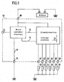
- FIG. 1 a system for controlling the glow process, in particular during the quick start of diesel engines (self-igniters) with controllable glow plugs for preheating during the start process, is shown schematically as a functional diagram.
- This comprises a battery with its negative electrode connected to ground (GND), the positive electrode of which is connected to a connection 29 of a control device 32.
- the control device 32 comprises a central control unit in the form of a micro-controller and a current monitor with power output stages, to which connections G1, G2, G3, G4, G5 and G6 are connected. Both the micro controller control and the current monitor are connected to the connection 29 for the voltage supply.
- the micro controller control is also connected via a line 12 to the current monitor and via a line 14 directly to the power output stages.
- the micro controller controller is connected via a line 16 to a connection 31 to which the common ground (GND) is connected.
- a further connection DL is provided, via which the micro-controller can be connected to an engine control (not shown in the drawing) or to an engine management system.
- Glow plugs 20, 22, 24, 26, 28 and 30 are connected to the connections G1 to G6 of the control device 32 and are also connected to the common ground GND.
- the structure of the micro controller control results from the block diagram of control unit 32 in FIG. 2.
- the micro controller control comprises a power supply unit, a microprocessor and a driver and protection circuit.
- the microprocessor and the driver and protection circuit are supplied with electrical energy by the power supply unit connected to the connection 29 of the control unit 32.
- the connection between micro-controller control and motor control or motor management shown schematically in FIG. 1 as connection DL takes place via a data interface.
- a single-wire connection or a CAN bus can be used.
- a separate power output stage is provided for each glow plug.
- the output stages are each connected to the driver and protective circuit of the microcontroller control and to a current measuring unit which in turn is connected to the driver and protective circuit and to connection 29.
- a separate output stage instead of assigning a separate output stage to each glow plug, provision can also be made to combine 2 or more glow plugs in a parallel connection and to connect a glow plug group formed in this way to an output stage.
- the connecting lines between the power output stages and the glow plugs 20 to 30 serve on the one hand to supply the glow plugs with electrical energy.
- the individual resistances and thus the temperature of the glow plugs are determined via these lines.
- their energy supply is briefly interrupted, and instead a test voltage is applied to the glow plugs and the current flowing through the filament is measured by the current measuring unit. This is done by controlling the output stages using the driver and protection circuit, which in turn is coupled to the microprocessor.
- the electrical resistance of the incandescent filament can be determined from the measured current, which in turn can be assigned a specific temperature value.
- the actual temperature determined in this way is compared with the target temperature of the glow plug, and the microprocessor uses the temperature difference to calculate the heating power required to reach the target temperature, which is then supplied to the glow plugs via the output stages.
- the heating power supply is interrupted for a period of about 55 ms, so that a temperature equilibrium is established within the glow plug.
- the current measurement for determining the resistance and thus also the temperature of the glow plug takes place at the end of the interruption interval, the measurement time being approximately 20 ⁇ s and the smallest measurable resolution of approximately 1 amp being achieved in a current measurement range of up to 200 amps.
- the glow plugs can be controlled by means of the control device 32 described above in such a way that the heating current supplied corresponds to the respective temperature difference between the actual and the target temperature.
- the resulting temperature and heating current curve is shown in Figure 3.
- FIG. 3 shows the course of the glow plug temperature T as a function of the time t, the glow plug temperature T changing due to the heating current I supplied to the glow plug, the course thereof, also as a function of the time t, in FIG. 3 in one lower diagram is shown.
- a high heating current I is first fed to the glow plug assigned in the respective power output stage, so that the glow plug heats up considerably.
- the heating current supply is reduced as the actual temperature increases. As a result, the actual temperature gradually approaches the target temperature of the glow plug.
- the actual temperature is determined in that the heating power supply, ie in the present case the supply of the corresponding heating current, briefly interrupted and the resistance of the filament is determined.
- the interruption of the heating current supply which takes place at regular intervals is shown enlarged in FIG. 4, which likewise shows the course of the heating current I as a function of the time t.
- FIG. 4 shows an enlarged illustration of the detail A drawn in broken lines in FIG. 3. The measurement of the resistance and thus also of the glow plug temperature takes place at the end of the interruption interval and is symbolized in FIG. 4 by the arrows 50.
- FIG. 5 shows in an upper diagram the course of the glow plug temperature T as a function of the time t, which results when the glow plug is activated in accordance with the control shown in a lower diagram in FIG. 5.
- the lower diagram shows the glow plug control, ie the course of the glow plug current as a function of time t.
- a heating current with maximum amplitude is constantly supplied to the glow plug assigned to the respective output stage during a heating phase indicated by the double arrow 55, so that the glow plug heats up very quickly, as can be seen from the upper diagram in FIG.
- the temperature of the glow plug during the subsequent holding phase which is indicated by the double arrow 60, kept constant.
- the glow plug is driven in a clocked manner, that is to say the heating current is interrupted regularly, so that, overall, a lower heating power is supplied to the glow plug over time.
- the glow plug can be supplied with a very high heating power during the heating phase, which it would not be able to withstand in continuous operation, but the supply of which, however, results in a very rapid heating to the desired temperature.
- the supplied heating power is reduced to a value which is sufficient to keep the temperature of the glow plug at the target temperature, so that there is no fear of the glow plug being destroyed.
- the heating-up phase and the subsequent maintenance of the temperature are not limited to the starting process of the diesel engine or to a maximum glow plug temperature, but can also be used for so-called intermediate annealing while the engine is running and at an annealing temperature determined by the diesel engine control.
- the heating current supply can also be interrupted regularly for a period of approximately 55 ms in the embodiment of the control shown in FIG. 5 and a temperature determination can be carried out at the end of the interruption interval, as described under Reference to Figures 3 and 4 has already been explained.
- a corresponding temperature determination can take place both during the heating phase 55 and during the holding phase 60.
- the corresponding output stage becomes Controlled by the microprocessor via the driver and protective circuit in such a way that the glow plug is constantly supplied with a heating current of maximum amplitude.
- the heating current is only clocked, that is, supplied with interruptions, as is clear from the lower diagram in FIG. 5.
- the duration of the interruption times ie the ratio of the on / off times of the output stages, can be calculated by the microprocessor by comparing the actual temperature with the target temperature of the respective glow plug.
Landscapes
- Engineering & Computer Science (AREA)
- Chemical & Material Sciences (AREA)
- Combustion & Propulsion (AREA)
- Mechanical Engineering (AREA)
- General Engineering & Computer Science (AREA)
- Combined Controls Of Internal Combustion Engines (AREA)
- Ignition Installations For Internal Combustion Engines (AREA)
Applications Claiming Priority (4)
| Application Number | Priority Date | Filing Date | Title |
|---|---|---|---|
| DE19620258 | 1996-05-21 | ||
| DE19620258 | 1996-05-21 | ||
| DE19708430A DE19708430A1 (de) | 1996-05-21 | 1997-03-01 | Verfahren und Vorrichtung zur Steuerung des Glühvorgangs einer Glühkerze eines Dieselmotors |
| DE19708430 | 1997-03-01 |
Publications (3)
| Publication Number | Publication Date |
|---|---|
| EP0809021A2 true EP0809021A2 (fr) | 1997-11-26 |
| EP0809021A3 EP0809021A3 (fr) | 1999-08-04 |
| EP0809021B1 EP0809021B1 (fr) | 2005-01-19 |
Family
ID=26025854
Family Applications (1)
| Application Number | Title | Priority Date | Filing Date |
|---|---|---|---|
| EP97108081A Expired - Lifetime EP0809021B1 (fr) | 1996-05-21 | 1997-05-17 | Méthode et dispositif de commande de préchauffage des bougies de réchauffage d'un moteur diesel |
Country Status (2)
| Country | Link |
|---|---|
| EP (1) | EP0809021B1 (fr) |
| ES (1) | ES2237782T3 (fr) |
Cited By (2)
| Publication number | Priority date | Publication date | Assignee | Title |
|---|---|---|---|---|
| DE10162253A1 (de) * | 2001-12-18 | 2003-07-10 | Daimler Chrysler Ag | Glüh- und Ionenstrommeßvorrichtung für einen Dieselmotor |
| US8017888B2 (en) | 2007-06-23 | 2011-09-13 | Bern Autiengesellschaft | Glow plug system, controlling device and method for controlling the power of a glow plug |
Families Citing this family (2)
| Publication number | Priority date | Publication date | Assignee | Title |
|---|---|---|---|---|
| DE102006042643A1 (de) | 2006-09-12 | 2008-03-27 | Beru Ag | Verfahren zum Verfolgen von Fehlfunktionen im Betrieb von Automobilen |
| DE102008052309A1 (de) | 2008-10-18 | 2010-04-22 | Man Nutzfahrzeuge Aktiengesellschaft | Flammstartanlage und Verfahren zu deren Steuerung |
Family Cites Families (8)
| Publication number | Priority date | Publication date | Assignee | Title |
|---|---|---|---|---|
| US4137885A (en) * | 1977-10-11 | 1979-02-06 | General Motors Corporation | Diesel engine glow plug energization control circuit |
| US4444160A (en) * | 1982-09-09 | 1984-04-24 | General Motors Corporation | Energization indication control for diesel glow plug |
| JP2547757B2 (ja) * | 1987-02-27 | 1996-10-23 | 日産自動車株式会社 | デイ−ゼル機関のグロ−制御装置 |
| JPS63266172A (ja) * | 1987-04-22 | 1988-11-02 | Mitsubishi Electric Corp | デイ−ゼルエンジンのグロ−プラグ制御装置 |
| EP0315934B1 (fr) * | 1987-11-09 | 1994-01-19 | Siemens Aktiengesellschaft | Méthode pour le réglage de la température des bougies dans un moteur diesel et circuit pour la réalisation de la méthode |
| JP2580296B2 (ja) * | 1988-11-30 | 1997-02-12 | 株式会社ゼクセル | 燃焼式ヒータのグロープラグ印加電圧制御装置 |
| US5144922A (en) * | 1990-11-01 | 1992-09-08 | Southwest Research Institute | Fuel ignition system for compression ignition engines |
| FR2689569B1 (fr) * | 1992-04-07 | 1996-06-14 | Renault | Perfectionnements aux moteurs diesel. |
-
1997
- 1997-05-17 ES ES97108081T patent/ES2237782T3/es not_active Expired - Lifetime
- 1997-05-17 EP EP97108081A patent/EP0809021B1/fr not_active Expired - Lifetime
Cited By (3)
| Publication number | Priority date | Publication date | Assignee | Title |
|---|---|---|---|---|
| DE10162253A1 (de) * | 2001-12-18 | 2003-07-10 | Daimler Chrysler Ag | Glüh- und Ionenstrommeßvorrichtung für einen Dieselmotor |
| EP1329630A3 (fr) * | 2001-12-18 | 2006-03-01 | Beru AG | Dispositif de préchauffage et de mesure de courant ionique pour un moteur Diesel |
| US8017888B2 (en) | 2007-06-23 | 2011-09-13 | Bern Autiengesellschaft | Glow plug system, controlling device and method for controlling the power of a glow plug |
Also Published As
| Publication number | Publication date |
|---|---|
| ES2237782T3 (es) | 2005-08-01 |
| EP0809021A3 (fr) | 1999-08-04 |
| EP0809021B1 (fr) | 2005-01-19 |
Similar Documents
| Publication | Publication Date | Title |
|---|---|---|
| EP2024634B1 (fr) | Procédé de commande d'une bougie de préchauffage dans un moteur diesel | |
| DE102007014677B4 (de) | Einrichtung und Verfahren zum Steuern der Stromversorgung einer Glühkerze | |
| DE2925351C2 (de) | Steuervorrichtung für die Glühkerzen einer Diesel-Brennkraftmaschine | |
| EP2122157A1 (fr) | Procédé et dispositif de commande d'excitation de bougie de préchauffage | |
| DE2906731C2 (de) | Vorrichtung zur Steuerung der Glühkerzen einer Diesel-Brennkraftmaschine | |
| DE19605216C2 (de) | Verfahren zum Betreiben eines Fahrzeugzusatzheizgerätes und Glüheinrichtung | |
| DE102006000119B4 (de) | Glühkerzenspeisungssteuerung zur Vermeidung einer Überhitzung | |
| EP2572099B1 (fr) | Procédé et dispositif de réduction de la tolérance à la température de bougies-crayons de préchauffage | |
| DE10025953C2 (de) | Verfahren zum Ansteuern eines Glühstifts zum Zünden eines Fahrzeugheizgeräts | |
| DE19936729C1 (de) | Verfahren zum Ansteuern eines Glühstifts für das Zünden eines Fahrzeugheizgeräts | |
| EP2678552B1 (fr) | Procédé et appareil de commande pour régler une température d'une bougie-crayon de préchauffage | |
| DE4041630C2 (fr) | ||
| EP0991537B1 (fr) | Chauffage electrique d'appoint pour vehicules | |
| EP0809021B1 (fr) | Méthode et dispositif de commande de préchauffage des bougies de réchauffage d'un moteur diesel | |
| DE102006010083A1 (de) | Verfahren zum Ansteuern einer Gruppe von Glühkerzen in einem Dieselmotor | |
| DE10135880A1 (de) | Verfahren und Vorrichtung zum Steuern der Aufheizung der Glühkerzen eines Dieselmotors | |
| EP3054216B1 (fr) | Procede de commande pour le processus d'allumage d'un appareil de chauffage a combustible | |
| EP2596233B1 (fr) | Procédé et dispositif de commande du comportement d'incandescence d'une bougie-crayon incandescente d'un moteur à combustion interne | |
| DE19708430A1 (de) | Verfahren und Vorrichtung zur Steuerung des Glühvorgangs einer Glühkerze eines Dieselmotors | |
| DE19940802A1 (de) | Anordnung zum elektrischen Beheizen eines Katalysators | |
| DE102018122678B4 (de) | Ladevorrichtung für ein Fahrzeug | |
| EP0305736B1 (fr) | Procédé de commande des bougies à incandescence d'un moteur à combustion à allumage par compression | |
| DE102005052879A1 (de) | Verfahren zum Betreiben einer Brennkraftmaschine und Brennkraftmaschine | |
| DE2840640C2 (de) | Flammstartanlage | |
| DE3402992A1 (de) | Regelung einer brennkraftmaschine mittels einer heissen stelle |
Legal Events
| Date | Code | Title | Description |
|---|---|---|---|
| PUAI | Public reference made under article 153(3) epc to a published international application that has entered the european phase |
Free format text: ORIGINAL CODE: 0009012 |
|
| AK | Designated contracting states |
Kind code of ref document: A2 Designated state(s): DE ES FR GB IT |
|
| PUAL | Search report despatched |
Free format text: ORIGINAL CODE: 0009013 |
|
| AK | Designated contracting states |
Kind code of ref document: A3 Designated state(s): DE ES FR GB IT |
|
| 17P | Request for examination filed |
Effective date: 20000121 |
|
| 17Q | First examination report despatched |
Effective date: 20020422 |
|
| GRAP | Despatch of communication of intention to grant a patent |
Free format text: ORIGINAL CODE: EPIDOSNIGR1 |
|
| GRAS | Grant fee paid |
Free format text: ORIGINAL CODE: EPIDOSNIGR3 |
|
| GRAA | (expected) grant |
Free format text: ORIGINAL CODE: 0009210 |
|
| RAP1 | Party data changed (applicant data changed or rights of an application transferred) |
Owner name: BERU AKTIENGESELLSCHAFT Owner name: ALCOA FUJIKURA GESELLSCHAFT MIT BESCHRAENKTER HAFT |
|
| AK | Designated contracting states |
Kind code of ref document: B1 Designated state(s): DE ES FR GB IT |
|
| REG | Reference to a national code |
Ref country code: GB Ref legal event code: FG4D Free format text: NOT ENGLISH |
|
| REF | Corresponds to: |
Ref document number: 59712164 Country of ref document: DE Date of ref document: 20050224 Kind code of ref document: P |
|
| GBT | Gb: translation of ep patent filed (gb section 77(6)(a)/1977) |
Effective date: 20050412 |
|
| REG | Reference to a national code |
Ref country code: ES Ref legal event code: FG2A Ref document number: 2237782 Country of ref document: ES Kind code of ref document: T3 |
|
| PLBE | No opposition filed within time limit |
Free format text: ORIGINAL CODE: 0009261 |
|
| STAA | Information on the status of an ep patent application or granted ep patent |
Free format text: STATUS: NO OPPOSITION FILED WITHIN TIME LIMIT |
|
| ET | Fr: translation filed | ||
| 26N | No opposition filed |
Effective date: 20051020 |
|
| REG | Reference to a national code |
Ref country code: GB Ref legal event code: 732E Free format text: REGISTERED BETWEEN 20100107 AND 20100113 |
|
| REG | Reference to a national code |
Ref country code: FR Ref legal event code: TQ Ref country code: FR Ref legal event code: CD Ref country code: FR Ref legal event code: CA |
|
| REG | Reference to a national code |
Ref country code: FR Ref legal event code: PLFP Year of fee payment: 20 |
|
| PGFP | Annual fee paid to national office [announced via postgrant information from national office to epo] |
Ref country code: ES Payment date: 20160527 Year of fee payment: 20 Ref country code: DE Payment date: 20160518 Year of fee payment: 20 Ref country code: GB Payment date: 20160518 Year of fee payment: 20 |
|
| PGFP | Annual fee paid to national office [announced via postgrant information from national office to epo] |
Ref country code: FR Payment date: 20160526 Year of fee payment: 20 Ref country code: IT Payment date: 20160524 Year of fee payment: 20 |
|
| REG | Reference to a national code |
Ref country code: DE Ref legal event code: R071 Ref document number: 59712164 Country of ref document: DE |
|
| REG | Reference to a national code |
Ref country code: GB Ref legal event code: PE20 Expiry date: 20170516 |
|
| PG25 | Lapsed in a contracting state [announced via postgrant information from national office to epo] |
Ref country code: GB Free format text: LAPSE BECAUSE OF EXPIRATION OF PROTECTION Effective date: 20170516 |
|
| REG | Reference to a national code |
Ref country code: ES Ref legal event code: FD2A Effective date: 20170825 |
|
| PG25 | Lapsed in a contracting state [announced via postgrant information from national office to epo] |
Ref country code: ES Free format text: LAPSE BECAUSE OF EXPIRATION OF PROTECTION Effective date: 20170518 |