EP0809038A2 - Support hydraulique - Google Patents
Support hydraulique Download PDFInfo
- Publication number
- EP0809038A2 EP0809038A2 EP96118800A EP96118800A EP0809038A2 EP 0809038 A2 EP0809038 A2 EP 0809038A2 EP 96118800 A EP96118800 A EP 96118800A EP 96118800 A EP96118800 A EP 96118800A EP 0809038 A2 EP0809038 A2 EP 0809038A2
- Authority
- EP
- European Patent Office
- Prior art keywords
- bearing
- axial
- radial
- spring body
- support bearing
- Prior art date
- Legal status (The legal status is an assumption and is not a legal conclusion. Google has not performed a legal analysis and makes no representation as to the accuracy of the status listed.)
- Granted
Links
- 230000006835 compression Effects 0.000 claims abstract description 34
- 238000007906 compression Methods 0.000 claims abstract description 34
- 238000005192 partition Methods 0.000 claims description 9
- 238000013016 damping Methods 0.000 claims description 8
- 239000000463 material Substances 0.000 claims description 5
- 239000013536 elastomeric material Substances 0.000 claims description 4
- 239000007788 liquid Substances 0.000 claims description 4
- 239000012528 membrane Substances 0.000 description 5
- 238000004073 vulcanization Methods 0.000 description 4
- 238000000926 separation method Methods 0.000 description 3
- 238000002485 combustion reaction Methods 0.000 description 2
- 238000005096 rolling process Methods 0.000 description 2
- 238000010521 absorption reaction Methods 0.000 description 1
- 238000010276 construction Methods 0.000 description 1
- 230000000694 effects Effects 0.000 description 1
- 239000007769 metal material Substances 0.000 description 1
- 238000007789 sealing Methods 0.000 description 1
- 239000007787 solid Substances 0.000 description 1
Images

Classifications
-
- F—MECHANICAL ENGINEERING; LIGHTING; HEATING; WEAPONS; BLASTING
- F16—ENGINEERING ELEMENTS AND UNITS; GENERAL MEASURES FOR PRODUCING AND MAINTAINING EFFECTIVE FUNCTIONING OF MACHINES OR INSTALLATIONS; THERMAL INSULATION IN GENERAL
- F16F—SPRINGS; SHOCK-ABSORBERS; MEANS FOR DAMPING VIBRATION
- F16F13/00—Units comprising springs of the non-fluid type as well as vibration-dampers, shock-absorbers, or fluid springs
- F16F13/04—Units comprising springs of the non-fluid type as well as vibration-dampers, shock-absorbers, or fluid springs comprising both a plastics spring and a damper, e.g. a friction damper
- F16F13/06—Units comprising springs of the non-fluid type as well as vibration-dampers, shock-absorbers, or fluid springs comprising both a plastics spring and a damper, e.g. a friction damper the damper being a fluid damper, e.g. the plastics spring not forming a part of the wall of the fluid chamber of the damper
- F16F13/08—Units comprising springs of the non-fluid type as well as vibration-dampers, shock-absorbers, or fluid springs comprising both a plastics spring and a damper, e.g. a friction damper the damper being a fluid damper, e.g. the plastics spring not forming a part of the wall of the fluid chamber of the damper the plastics spring forming at least a part of the wall of the fluid chamber of the damper
- F16F13/10—Units comprising springs of the non-fluid type as well as vibration-dampers, shock-absorbers, or fluid springs comprising both a plastics spring and a damper, e.g. a friction damper the damper being a fluid damper, e.g. the plastics spring not forming a part of the wall of the fluid chamber of the damper the plastics spring forming at least a part of the wall of the fluid chamber of the damper the wall being at least in part formed by a flexible membrane or the like
- F16F13/108—Units comprising springs of the non-fluid type as well as vibration-dampers, shock-absorbers, or fluid springs comprising both a plastics spring and a damper, e.g. a friction damper the damper being a fluid damper, e.g. the plastics spring not forming a part of the wall of the fluid chamber of the damper the plastics spring forming at least a part of the wall of the fluid chamber of the damper the wall being at least in part formed by a flexible membrane or the like characterised by features of plastics springs, e.g. attachment arrangements
Definitions
- the invention relates to a hydraulic bearing, comprising a support bearing and a support, which are supported on one another by a substantially frustoconical spring body made of elastomeric material and delimit a working and compensation space filled with damping liquid, which are separated from one another by a partition and connected in a liquid-conducting manner by a damping channel are, the spring body having two radially opposite compression spring sections and in the circumferential direction between the compression spring sections two radially opposite thrust spring sections.
- Such a hydraulic bearing is known from DE 37 07 445 A1.
- the spring body is connected by vulcanization to the rotationally symmetrical support bearing and the support, wherein the spring body has kidney-shaped areas with a small material thickness, which are opposite to each other and symmetrical to a transverse axis, and the areas consist of thin-walled, curved rolling bellows.
- the spring body is divided by an intermediate ring.
- a disadvantage of the known hydraulic bearing is that the heat conduction on the support bearing during vulcanization is not very satisfactory due to the intermediate ring within the spring body.
- the invention has for its object to develop a hydraulic bearing of the known type such that the radial spring rates of the compression spring sections and thrust spring sections deviate more from each other and that the vulcanization of the spring body with the support bearing and the support - regardless of the material of the support bearing - is improved.
- the support bearing overlaps the spring body in the compression spring sections in the radial direction and the spring body and the support bearing are connected to one another by a radial surface and that the support bearing and the spring body in the thrust spring sections by themselves axial surface extending essentially parallel to the axis of the hydraulic bearing are connected to one another. It is advantageous here that the radial spring rates of the compression and thrust spring sections differ greatly from one another due to the asymmetrical shape of the support bearing, without the need for a spring body in the intermediate ring.
- the compression spring sections comprise cross-soft compression springs, the support bearing in these sections preferably being produced by turning.
- the thrust spring is - based on the compression spring - more solid and has a very large connection height on the axial surface of the bearing.
- the compression spring sections and the shear spring sections can each be connected by imaginary planes, the planes preferably being arranged at right angles to one another.
- the support bearing preferably has a combined radial and axial stop extending radially on the inside in the compression spring sections, the radial and axial stop and the spring body being spaced apart from one another in the radial direction by a pocket.
- the pockets within the compression spring sections bring about a further reduction in the spring stiffness of the soft transverse spring, which is of advantage in many cases.
- the pockets preferably have a larger one Extent in the circumferential direction as the support bearing.
- the difference in the width of the pockets and the bearing has an influence on the radial spring ratio between the compression spring sections and the thrust spring sections. The greater the width of the pocket in relation to the width of the core, the softer the compression spring sections.
- the support bearing can have an axial extension in the thrust spring sections, which corresponds to the axial extension of the radial and axial stop in the compression spring sections, the support bearing being integrally formed in the thrust spring sections and merging with one another with an axial stop, and wherein the support bearing and the axial stop together on the outer circumference from the Axial area are limited.
- the combined radial and axial stop of the compression spring sections and the axial stop of the thrust spring sections are designed as spring-in stops to limit extreme deflection movements of the support bearing in relation to the support in the axial direction.
- the stops come into contact, for example, to limit extreme deflection movements with the partition wall, which separates the work space and the compensation space from one another. Due to the one-piece design of the stops with the support bearing, the entire hydraulic bearing has a low-parts, simple and inexpensive construction.
- the performance characteristics of the hydraulic bearing according to the invention are particularly advantageous when the ratio of the connection surface of the spring body on the axial surface to the connection surface of the spring body on the radial surface is at least two.
- the compression spring in the compression spring section is therefore cross-soft, the shear spring in the shear spring section is comparatively significantly harder due to the large connection surface of the spring body on the support bearing.
- the axial surface can be concavely curved and avoid sudden changes in direction.
- the curvature of the support bearing on the one hand increases the connection surface on the axial surface, which is advantageous with regard to a further improved durability and the resultant consistently good usage properties during the entire service life.
- the curvature further reduces the cross spring rate of the compression spring sections.
- the support bearing can be formed by a core which consists of polymeric material, the core having at least one recess on the side facing away from the support for receiving a vulcanizing tool and the wall thicknesses of the core being of essentially the same size.
- Support bearings made of a plastic are preferably used when the machine part supported on the support bearing radiates considerable heat in the direction of the hydraulic bearing, as is the case, for example, when the hydraulic bearing is used as a bearing for an internal combustion engine.
- a plastic core By using a plastic core, the transfer of the heat radiated from the internal combustion engine into the spring body is greatly reduced. However, this effect, which is desirable per se during operation of the hydraulic bearing, in principle makes it more difficult to vulcanize the plastic core with the spring body.
- the vulcanizing tool can be immersed in the recesses and support the core to vulcanize the spring body with the support bearing.
- the remaining, relatively thinner wall thickness makes vulcanization of the core with the spring body much easier.
- Fig. 2 shows a section through the hydraulic bearing of Fig. 1 along the line BC.
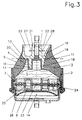
- Fig. 3 shows a second embodiment of a hydraulic bearing, similar to the embodiment of Fig. 1, wherein the support bearing is formed by a plastic core.
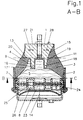
- Fig. 1 an embodiment of a hydraulic bearing according to the invention is shown, in which a support bearing 1 and a support 2 are connected by the spring body 3.
- the working space 5 is delimited by the support bearing 1, the spring body 3 and a partition 7 and filled with a damping liquid 4.
- the partition 7 comprises a damping channel 8, which connects the working chamber 5 and the compensation chamber 6 in a liquid-conducting manner.
- the damping channel 8 consists of two sub-channels 8.1, 8.2, which are arranged in a functional series connection, the sub-channels 8.1, 8.2 being arranged in the axial direction on both sides of an oscillatable membrane 23 made of elastomeric material, which forms part of the partition 7, wherein the membrane 23 is provided with a channel separation 24 and has at least one recess 25 within the channel separation 24 for the liquid-conducting connection of the subchannels 8.1, 8.2.
- the subchannels 8.1, 8.2 each have a groove-shaped cross section that is open axially in the direction of the membrane 23, the end faces of the subchannels 8.1, 8.2 and the channel separation 24 of the membrane 23 being supported against one another in a sealing manner under axial prestress.
- the damping channel has a long length, but the membrane 23 nevertheless has a large area for isolating higher-frequency vibrations.
- the compensation chamber 6 is delimited on the side facing away from the partition 7 by a rolling bellows 26 made of elastomeric material and is suitable for largely pressureless absorption of liquid components from the working chamber 5.
- the right-angled cut A-B in FIG. 2 shows both a compression spring section 9 and a thrust spring section 11 in FIG. 1.
- the support bearing 1 is formed asymmetrically in the compression spring section 9 with respect to the thrust spring section 11, as is the spring body 3. In the compression spring section 9, the support bearing 1 overlaps the spring body 3 in the radial direction, the spring body being vulcanized onto a radial surface 13 of the support bearing 1.
- the support bearing 1 is provided in the compression spring sections 9, 10 with a one-piece combined radial and axial stop 16, the radial and axial stop 16 being spaced apart in the radial direction from the spring body 3 by a pocket 17.
- the cross-soft direction is symbolized by the arrow with the reference numeral 27, the cross-hard direction by the arrow, which is designated 28.
- the spring body 3 is vulcanized in the thrust spring sections 11, 12 to the axial surface 15 of the support bearing 1, the axial surface 15 extending essentially parallel to the axis 14 of the hydraulic bearing.
- the thrust spring sections 11, 12 of the support bearing 1 comprise an axial stop 18 which is formed in one piece with the support bearing 1 and forms part of the axial surface 15.
- the radial and axial stop 16 and the axial stop 18 extend equally far into the working space 5 in the axial direction.
- the stops 16, 18 strike the partition 7.
- FIG. 2 shows a section through the hydraulic bearing from FIG. 1 along the line BC. It can be seen that the compression spring sections 9, 10 and the thrust spring sections 11, 12 are arranged uniformly distributed in the circumferential direction, an imaginary first plane connecting the two compression spring sections 9, 109 to an imaginary second plane, which connects the two thrust spring sections 11, 12 connects to each other, is arranged vertically.
- the pockets 17, which are arranged within the spring body 3 in the compression spring sections 9, 10, have a greater width than the support bearing 1, the width difference 29 influencing the radial spring rate ratio between compression spring sections 9, 10 and thrust spring sections 11, 12 takes. In order to achieve a spring rate of the first compression spring sections 9, 10 that is as soft as possible 27, the width of the pockets 17 is greater than the width of the support bearing 1.
- the supporting bearing 1 consists of a core 21 made of polymeric material. Recesses 22 are provided within the core 21 for receiving a vulcanizing tool.
- the wall thicknesses of the core 21 are essentially of the same size.
- connection surface 19 of the thrust spring sections 11, 12 to the axial surface 15 is significantly larger than the connection surface 20 of the compression spring sections 9, 10 to the radial surface 13.
Landscapes
- Engineering & Computer Science (AREA)
- General Engineering & Computer Science (AREA)
- Mechanical Engineering (AREA)
- Combined Devices Of Dampers And Springs (AREA)
- Support Of The Bearing (AREA)
- Springs (AREA)
Applications Claiming Priority (2)
| Application Number | Priority Date | Filing Date | Title |
|---|---|---|---|
| DE19620976 | 1996-05-24 | ||
| DE19620976A DE19620976C2 (de) | 1996-05-24 | 1996-05-24 | Hydrolager |
Publications (3)
| Publication Number | Publication Date |
|---|---|
| EP0809038A2 true EP0809038A2 (fr) | 1997-11-26 |
| EP0809038A3 EP0809038A3 (fr) | 1997-12-29 |
| EP0809038B1 EP0809038B1 (fr) | 2001-10-10 |
Family
ID=7795233
Family Applications (1)
| Application Number | Title | Priority Date | Filing Date |
|---|---|---|---|
| EP96118800A Expired - Lifetime EP0809038B1 (fr) | 1996-05-24 | 1996-11-23 | Support hydraulique |
Country Status (5)
| Country | Link |
|---|---|
| US (1) | US5895032A (fr) |
| EP (1) | EP0809038B1 (fr) |
| JP (1) | JP3010029B2 (fr) |
| BR (1) | BR9703835A (fr) |
| DE (2) | DE19620976C2 (fr) |
Families Citing this family (10)
| Publication number | Priority date | Publication date | Assignee | Title |
|---|---|---|---|---|
| DE10064330A1 (de) * | 2000-12-21 | 2002-07-11 | Freudenberg Carl Kg | Hydrolager |
| JP3963346B2 (ja) * | 2001-07-17 | 2007-08-22 | 北辰工業株式会社 | エンジンマウント |
| ES2293963T3 (es) * | 2001-12-07 | 2008-04-01 | Synthes Gmbh | Elemento amortiguador para la columna vertebral. |
| JP4803605B2 (ja) * | 2007-03-22 | 2011-10-26 | 本田技研工業株式会社 | 液封防振装置 |
| US20090289472A1 (en) * | 2008-04-02 | 2009-11-26 | Catanzarite David M | Construction vehicle cab suspension mount |
| US20110169204A1 (en) * | 2008-04-02 | 2011-07-14 | Lord Corporation | construction vehicle cab suspension surface effect liquid mount |
| JP6300406B2 (ja) * | 2014-04-24 | 2018-03-28 | 株式会社ブリヂストン | 防振装置 |
| JP6886286B2 (ja) * | 2016-12-21 | 2021-06-16 | Toyo Tire株式会社 | 防振装置 |
| JP6886287B2 (ja) | 2016-12-21 | 2021-06-16 | Toyo Tire株式会社 | 防振装置 |
| US12104670B2 (en) * | 2019-11-13 | 2024-10-01 | Prospira Corporation | Vibration-damping device |
Citations (1)
| Publication number | Priority date | Publication date | Assignee | Title |
|---|---|---|---|---|
| DE3707445A1 (de) | 1987-03-07 | 1988-09-15 | Diehl Gmbh & Co | Hydrolager mit einem gummielastischen, konischen stuetzkoerper |
Family Cites Families (13)
| Publication number | Priority date | Publication date | Assignee | Title |
|---|---|---|---|---|
| FR346227A (fr) * | 1904-09-14 | 1905-01-07 | Benjamin Howard Thwaite | Perfectionnements apportés dans les moteurs verticaux à combustion interne |
| FR596787A (fr) * | 1924-07-24 | 1925-10-31 | Coussin auxiliaire pour voitures | |
| DE1455607A1 (de) * | 1964-03-10 | 1969-06-19 | Metzeler Ag | Elastisches Motorlager |
| DE3225701C2 (de) * | 1982-07-09 | 1986-03-20 | Fa. Carl Freudenberg, 6940 Weinheim | Elastisches Gummilager |
| DE3225700C1 (de) * | 1982-07-09 | 1983-11-17 | Fa. Carl Freudenberg, 6940 Weinheim | Elastisches Gummilager |
| FR2560326B1 (fr) * | 1984-02-27 | 1988-07-29 | Hutchinson | Perfectionnements aux supports antivibratoires hydrauliques |
| US4903951A (en) * | 1987-05-12 | 1990-02-27 | Honda Giken Kogyo Kabushiki Kaisha | Fluid-filled vibroisolating device |
| DE3937232A1 (de) * | 1989-11-09 | 1991-05-16 | Freudenberg Carl Fa | Gummilager mit hydraulischer daempfung |
| US5029824A (en) * | 1989-12-26 | 1991-07-09 | General Motors Corporation | Hydraulic engine mount with pressure relief valve |
| DE4036517A1 (de) * | 1990-11-16 | 1992-05-21 | Phoenix Ag | Elastisches lager |
| DE4216185C2 (de) * | 1992-05-15 | 1994-12-08 | Boge Gmbh | Elastisches Gummilager |
| JPH06235437A (ja) * | 1993-02-04 | 1994-08-23 | Toyoda Gosei Co Ltd | 防振ゴム |
| DE19515838C2 (de) * | 1995-04-29 | 1998-04-16 | Freudenberg Carl Fa | Hydraulisch dämpfendes Gummilager |
-
1996
- 1996-05-24 DE DE19620976A patent/DE19620976C2/de not_active Expired - Lifetime
- 1996-11-23 EP EP96118800A patent/EP0809038B1/fr not_active Expired - Lifetime
- 1996-11-23 DE DE59607880T patent/DE59607880D1/de not_active Expired - Lifetime
-
1997
- 1997-04-15 US US08/839,609 patent/US5895032A/en not_active Expired - Fee Related
- 1997-05-26 BR BR9703835A patent/BR9703835A/pt not_active Application Discontinuation
- 1997-05-26 JP JP9135242A patent/JP3010029B2/ja not_active Expired - Fee Related
Patent Citations (1)
| Publication number | Priority date | Publication date | Assignee | Title |
|---|---|---|---|---|
| DE3707445A1 (de) | 1987-03-07 | 1988-09-15 | Diehl Gmbh & Co | Hydrolager mit einem gummielastischen, konischen stuetzkoerper |
Also Published As
| Publication number | Publication date |
|---|---|
| JPH1047421A (ja) | 1998-02-20 |
| BR9703835A (pt) | 1998-08-11 |
| DE19620976C2 (de) | 1998-11-19 |
| US5895032A (en) | 1999-04-20 |
| DE59607880D1 (de) | 2001-11-15 |
| EP0809038A3 (fr) | 1997-12-29 |
| EP0809038B1 (fr) | 2001-10-10 |
| JP3010029B2 (ja) | 2000-02-14 |
| DE19620976A1 (de) | 1997-11-27 |
Similar Documents
| Publication | Publication Date | Title |
|---|---|---|
| DE4305173C2 (de) | Hydraulisch dämpfende Lagerbuchse | |
| DE19624886C2 (de) | Flüssigkeitsdämpfungsvorrichtung mit unterschiedlich großen Federsteifigkeitswerten in zwei zueinander senkrechten Richtungen | |
| DE3431460C2 (de) | Fluidgefüllte federnde Buchsenkonstruktion | |
| DE3927715C2 (de) | Elastische Aufhängung mit einer Fluidfüllung | |
| DE112013004246B4 (de) | Zylindrische Schwingungsdämpfungsvorrichtung | |
| DE3617787A1 (de) | Schwingungsdaempfer | |
| EP0332901B1 (fr) | Manchon élastique à amortissement hydraulique | |
| DE10036740A1 (de) | Schwingungsdämpfungseinrichtung, deren elastischer Körper eine gute Haltbarkeit aufweist | |
| DE3342300C2 (fr) | ||
| WO2002084143A1 (fr) | Palier a coussinet-douille a amortissement hydraulique | |
| EP0809038B1 (fr) | Support hydraulique | |
| EP0300093A1 (fr) | Ressort du type à manchon en caoutchouc | |
| EP1181465B1 (fr) | Support elastique a comportement d'amortissement graduel | |
| EP0810386A2 (fr) | Support hydraulique | |
| DE4117128A1 (de) | Hydraulisch daempfendes lager | |
| EP1770303A1 (fr) | Support en élastomère à amortissement hydraulique | |
| DE112019003332T5 (de) | Fluidgefüllte vibrationsdämpfungsvorrichtung | |
| EP0331951A2 (fr) | Membrane de découplage pour support de moteur à plusieurs chambres et à amortissement hydraulique | |
| EP1580451B1 (fr) | Manchon à amortissement hydraulique | |
| DE4426588C2 (de) | Querweiche Tragfeder für ein Hydrolager | |
| DE3512555C2 (de) | Schallisolierendes Lager | |
| EP1035349B1 (fr) | Support élastomérique avec butées axiales et méthode de fabrication d'un tel support | |
| DE19620835B4 (de) | Hydraulikaufbau | |
| EP1235989A1 (fr) | Palier pour levier pivotant | |
| DE4438931C2 (de) | Hydrolager |
Legal Events
| Date | Code | Title | Description |
|---|---|---|---|
| PUAI | Public reference made under article 153(3) epc to a published international application that has entered the european phase |
Free format text: ORIGINAL CODE: 0009012 |
|
| PUAL | Search report despatched |
Free format text: ORIGINAL CODE: 0009013 |
|
| AK | Designated contracting states |
Kind code of ref document: A2 Designated state(s): DE FR GB IT |
|
| AK | Designated contracting states |
Kind code of ref document: A3 Designated state(s): DE FR GB IT |
|
| 17P | Request for examination filed |
Effective date: 19971121 |
|
| GRAG | Despatch of communication of intention to grant |
Free format text: ORIGINAL CODE: EPIDOS AGRA |
|
| GRAG | Despatch of communication of intention to grant |
Free format text: ORIGINAL CODE: EPIDOS AGRA |
|
| GRAH | Despatch of communication of intention to grant a patent |
Free format text: ORIGINAL CODE: EPIDOS IGRA |
|
| 17Q | First examination report despatched |
Effective date: 20010322 |
|
| GRAH | Despatch of communication of intention to grant a patent |
Free format text: ORIGINAL CODE: EPIDOS IGRA |
|
| GRAA | (expected) grant |
Free format text: ORIGINAL CODE: 0009210 |
|
| AK | Designated contracting states |
Kind code of ref document: B1 Designated state(s): DE FR GB IT |
|
| REF | Corresponds to: |
Ref document number: 59607880 Country of ref document: DE Date of ref document: 20011115 |
|
| REG | Reference to a national code |
Ref country code: GB Ref legal event code: IF02 |
|
| GBT | Gb: translation of ep patent filed (gb section 77(6)(a)/1977) |
Effective date: 20011220 |
|
| RAP2 | Party data changed (patent owner data changed or rights of a patent transferred) |
Owner name: CARL FREUDENBERG KG |
|
| ET | Fr: translation filed | ||
| PLBE | No opposition filed within time limit |
Free format text: ORIGINAL CODE: 0009261 |
|
| STAA | Information on the status of an ep patent application or granted ep patent |
Free format text: STATUS: NO OPPOSITION FILED WITHIN TIME LIMIT |
|
| 26N | No opposition filed | ||
| PG25 | Lapsed in a contracting state [announced via postgrant information from national office to epo] |
Ref country code: IT Free format text: LAPSE BECAUSE OF NON-PAYMENT OF DUE FEES;WARNING: LAPSES OF ITALIAN PATENTS WITH EFFECTIVE DATE BEFORE 2007 MAY HAVE OCCURRED AT ANY TIME BEFORE 2007. THE CORRECT EFFECTIVE DATE MAY BE DIFFERENT FROM THE ONE RECORDED. Effective date: 20051123 |
|
| REG | Reference to a national code |
Ref country code: FR Ref legal event code: PLFP Year of fee payment: 20 |
|
| PGFP | Annual fee paid to national office [announced via postgrant information from national office to epo] |
Ref country code: GB Payment date: 20151123 Year of fee payment: 20 Ref country code: DE Payment date: 20151125 Year of fee payment: 20 |
|
| PGFP | Annual fee paid to national office [announced via postgrant information from national office to epo] |
Ref country code: FR Payment date: 20151123 Year of fee payment: 20 |
|
| REG | Reference to a national code |
Ref country code: DE Ref legal event code: R071 Ref document number: 59607880 Country of ref document: DE |
|
| REG | Reference to a national code |
Ref country code: GB Ref legal event code: PE20 Expiry date: 20161122 |
|
| PG25 | Lapsed in a contracting state [announced via postgrant information from national office to epo] |
Ref country code: GB Free format text: LAPSE BECAUSE OF EXPIRATION OF PROTECTION Effective date: 20161122 |