EP0809060A2 - Raccord articulé pour un collier de serrage - Google Patents
Raccord articulé pour un collier de serrage Download PDFInfo
- Publication number
- EP0809060A2 EP0809060A2 EP97108278A EP97108278A EP0809060A2 EP 0809060 A2 EP0809060 A2 EP 0809060A2 EP 97108278 A EP97108278 A EP 97108278A EP 97108278 A EP97108278 A EP 97108278A EP 0809060 A2 EP0809060 A2 EP 0809060A2
- Authority
- EP
- European Patent Office
- Prior art keywords
- articulated
- joint
- clamp
- opening
- connection according
- Prior art date
- Legal status (The legal status is an assumption and is not a legal conclusion. Google has not performed a legal analysis and makes no representation as to the accuracy of the status listed.)
- Withdrawn
Links
Images

Classifications
-
- F—MECHANICAL ENGINEERING; LIGHTING; HEATING; WEAPONS; BLASTING
- F16—ENGINEERING ELEMENTS AND UNITS; GENERAL MEASURES FOR PRODUCING AND MAINTAINING EFFECTIVE FUNCTIONING OF MACHINES OR INSTALLATIONS; THERMAL INSULATION IN GENERAL
- F16L—PIPES; JOINTS OR FITTINGS FOR PIPES; SUPPORTS FOR PIPES, CABLES OR PROTECTIVE TUBING; MEANS FOR THERMAL INSULATION IN GENERAL
- F16L3/00—Supports for pipes, cables or protective tubing, e.g. hangers, holders, clamps, cleats, clips, brackets
- F16L3/08—Supports for pipes, cables or protective tubing, e.g. hangers, holders, clamps, cleats, clips, brackets substantially surrounding the pipe, cable or protective tubing
- F16L3/10—Supports for pipes, cables or protective tubing, e.g. hangers, holders, clamps, cleats, clips, brackets substantially surrounding the pipe, cable or protective tubing divided, i.e. with two members engaging the pipe, cable or protective tubing
- F16L3/11—Supports for pipes, cables or protective tubing, e.g. hangers, holders, clamps, cleats, clips, brackets substantially surrounding the pipe, cable or protective tubing divided, i.e. with two members engaging the pipe, cable or protective tubing and hanging from a pendant
-
- F—MECHANICAL ENGINEERING; LIGHTING; HEATING; WEAPONS; BLASTING
- F16—ENGINEERING ELEMENTS AND UNITS; GENERAL MEASURES FOR PRODUCING AND MAINTAINING EFFECTIVE FUNCTIONING OF MACHINES OR INSTALLATIONS; THERMAL INSULATION IN GENERAL
- F16L—PIPES; JOINTS OR FITTINGS FOR PIPES; SUPPORTS FOR PIPES, CABLES OR PROTECTIVE TUBING; MEANS FOR THERMAL INSULATION IN GENERAL
- F16L3/00—Supports for pipes, cables or protective tubing, e.g. hangers, holders, clamps, cleats, clips, brackets
- F16L3/08—Supports for pipes, cables or protective tubing, e.g. hangers, holders, clamps, cleats, clips, brackets substantially surrounding the pipe, cable or protective tubing
- F16L3/10—Supports for pipes, cables or protective tubing, e.g. hangers, holders, clamps, cleats, clips, brackets substantially surrounding the pipe, cable or protective tubing divided, i.e. with two members engaging the pipe, cable or protective tubing
- F16L3/1008—Supports for pipes, cables or protective tubing, e.g. hangers, holders, clamps, cleats, clips, brackets substantially surrounding the pipe, cable or protective tubing divided, i.e. with two members engaging the pipe, cable or protective tubing with two members engaging the pipe, cable or tubing, both being made of thin band material completely surrounding the pipe
-
- F—MECHANICAL ENGINEERING; LIGHTING; HEATING; WEAPONS; BLASTING
- F16—ENGINEERING ELEMENTS AND UNITS; GENERAL MEASURES FOR PRODUCING AND MAINTAINING EFFECTIVE FUNCTIONING OF MACHINES OR INSTALLATIONS; THERMAL INSULATION IN GENERAL
- F16L—PIPES; JOINTS OR FITTINGS FOR PIPES; SUPPORTS FOR PIPES, CABLES OR PROTECTIVE TUBING; MEANS FOR THERMAL INSULATION IN GENERAL
- F16L55/00—Devices or appurtenances for use in, or in connection with, pipes or pipe systems
- F16L55/02—Energy absorbers; Noise absorbers
- F16L55/033—Noise absorbers
- F16L55/035—Noise absorbers in the form of specially adapted hangers or supports
Definitions
- a joint of the type mentioned which articulates two edge clamps which are adjacent to one another and which are designed as workpieces or components of an articulated screw pipe clamp.
- a clamp bracket to be designated as the first workpiece has a first joint part, which is designed as an approximately T-shaped joint opening
- a cross bolt is provided as the second joint part on the other clamp bracket serving as the second workpiece.
- This second joint part which can be inserted into the joint opening until it engages behind the opening edges in a form-fitting manner, is also connected to the second clamp bracket in a T-shape by means of a web-shaped cross-sectional constriction.
- the second joint part has a web-shaped area or partial area that can be inserted into the first joint part.
- this preferred embodiment Since a load acting on the workpieces, the load of which presses the crossbar of the second joint part behind the bend (s) or the like, recess (s) in the direction of the other workpiece, or the recess (s) of the second joint part in the joint opening of the first joint part presses, the form fit of this joint connection increases, this preferred embodiment has an almost self-locking effect.
- the offsets or similar recesses simultaneously serve as mutual supports or guides for the articulated parts, by forming a type of rotation or swiveling axis in which the articulated parts slide past one another.
- the bending process can be carried out particularly easily if the free web ends of the U-shaped or V-shaped transverse bar for insertion are each angled outwards.
- the crossbar for securing the second joint part can be deformed into an approximately straight cross section. Since the joint opening in this embodiment has a transverse axis that deviates from a straight line, the transverse bar, which is, in contrast, just deformed, is in the joint opening or kept particularly stable and permanent on the bend.
- At least one material or securing tab is provided on the first workpiece in the region of the joint opening, which is deformable from an angled open position in the direction of the joint opening into a securing position for securing the second joint part in the joint opening.
- the latter Before the second joint part is inserted into the joint opening, the latter has a particularly large opening cross-section if the material or securing tab delimited by the joint opening is angled. After the second joint part has been inserted, this securing tab can be bent in the direction of the joint opening, as a result of which the opening cross section changes in such a way that the joint part serving as a cross bolt is held captively therein.
- the second joint part has a cross bar which is connected to the second workpiece via a plurality of webs; This second joint part can also be inserted into the first joint part. What has been said so far also applies analogously to this embodiment.
- joint-side ends of the workpieces are arranged on the same side of these workpieces in the position of use of the joint and in this position lie against one another in an overlapping manner.
- An aesthetically particularly appealing embodiment according to the invention provides that the articulated ends of the workpieces are arranged on the side of the workpieces facing away from the visible side.
- the joint can be arranged virtually invisibly behind the workpieces on the side facing away from the visible side.
- the joint parts also no longer protrude outwardly. A risk of injury is practically excluded. This applies in particular to the case where the joint is used for pipe clamps, which are installed in kindergartens or living rooms, for example, where people can come into contact with pipes and pipe clamps. Another advantage of this pipe clamp can also be seen in terms of the heat and / or sound insulation of a pipeline: since it has no joint parts projecting outwards, the insulation work is not made more difficult and the insulation effect is not reduced in the area of the joint.
- the adjoining clamp ends are held against one another with practically no play and additionally guided into one another when the joint is pivoted.
- the clamp ends at least in their joint-side end region, preferably have a clamp edge that is angled radially inwards on both sides.
- the clamp insert is designed in the form and / or material as a sound insulation insert.
- a further embodiment according to the invention provides that the articulated ends of the workpieces protrude outward on the visible side of the workpieces and that in particular the articulated clamp ends of a pipe clamp protrude radially outward.
- a pipe clamp that consists of two clamp halves, which have a radially outwardly projecting fastening flange on their clamp ends facing away from the joint for screwing these clamp ends
- an essentially symmetrical configuration of the pipe clamp can also be achieved by means of the joint-sided clamp ends that also protrude outwards, which also high aesthetic standards are sufficient.
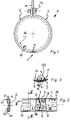
- a joint 1 is shown in different designs in FIGS. 1 to 19, which serves for the articulated connection of two workpieces 2, 3 adjoining one another on the edge.
- These workpieces 2, 3 are configured here as clamp brackets 2, 3, which each form a pipe clamp 4 as clamp halves.
- a first workpiece 2 (first clamp bracket 2) has a first joint part designed as a joint opening 5, while the clamp bracket 3 designated as a second workpiece is connected to the crossbar 16 of a second joint part 7 via a web-shaped cross-sectional constriction 6.
- the second joint part 7 can be inserted into the joint opening 5 up to regions with the cross-sectional constriction 6, so that in the use position of the joint 1 the opening edges 8 of the joint opening 5 engage behind the cross bar 16 of the second joint part 7.
- the first joint part 5 has two offsets or similar recesses 20 (cf. FIGS. 3 and 6). These offsets or recesses 20 are positively engaged behind by the cross bar 16 of the second joint part 7 in the functional position of the articulation.
- the second joint part 7 also has an offset or similar recess 17 on its web-shaped cross-sectional constriction 6, which connects the cross bar 16 to the clamp bracket 3. In the position of use shown in FIG. 3, this recess 17 engages positively behind the edge region of the clamp bracket 2 which delimits the joint opening 5 and is oriented towards the free end of the first joint part 5.
- recesses 17, 20 ensure a secure and positive connection of the joint parts 5, 7. Since, when the pipe clamp 4 is loaded, for example by clamping a pipe, the cross bar 16 is pressed behind the recesses 20 in the direction of the other clamp bracket, or the recess 17 is additionally pressed into the joint opening 5, and the positive engagement of this joint connection increases, the joint 1 has an almost self-locking effect.
- the recesses 17, 20 can serve as supports / guide surfaces for their joint partner pieces if the workpieces 2, 3 connected via the joint connection are pivoted.
- the joint opening 5 has an opening center line which deviates from a straight line.
- the joint opening 5 provided in the extension of the first clamp bracket 2 has a V-shaped or preferably U-shaped clear outline.
- the cross bar 16 of the second joint part 7 is adapted to the shape of the articulated cross section of the joint opening 5 for insertion.
- the cross bar 16 of the second joint part 7 can be deformed in its position of use into a cross-sectional shape that is preferably flattened compared to the joint opening 5, for which purpose - as shown in FIG. 2 - the free web or bar ends of the likewise V or preferably U-shaped cross bar 16 are bent.
- these free bar ends of the transverse bar 16 are each angled outwards, for example an angle ⁇ of approximately 20 ° (cf. FIG. 10) can be chosen between these still undeformed bar ends.
- edges 8 of the first clamp bracket 2 which delimit the joint opening 5 and are angled to insert the transverse bolt 16 in the use position of the second joint part 7 are deformable in the direction of the joint opening 5 such that these edges 8 then engage behind the second joint part 7 in the area of the cross bar 16 in a form-fitting manner.
- the securing tab 9 of the first workpiece 2, delimited by the U-shaped or V-shaped joint opening 5, can initially be angled for inserting the second joint part 7, as a result of which the joint opening 5 has an outline through which even a crossbar 16 can be inserted, which is a Compared to the opening cross-section of the joint opening 5, the cross-sectional shape differs, for example its elongated or straight cross-sectional shape according to FIG. 2. However, an initially U- or V-shaped cross bar 16 is easiest to insert before it is bent into its straight cross-sectional shape, the securing tab is deformed to the joint opening and the captive connection of these joint parts 2, 3 is established.
- the clamp brackets 2, 3 on the joint side and integrally connected to the joint parts 5, 7 are arranged in the position of use of the joint 1 on the same side of these workpieces 2, 3.
- these articulated ends are arranged on the side of the workpieces 2, 3 facing away from the visible side.
- the joint 1 is therefore practically not visible in the pipe clamp 4 according to FIGS. 1 to 10, but rather is covered by the outside of the clamp brackets 2, 3 adjoining one another on the edge.
- the shape of the hinge parts in the final assembly state is adapted to the circular shape of the clamp bracket.
- the pipe clamp 4 shown in Figures 1 to 10 therefore also comes meet high aesthetic requirements, the articulated connection of their clamp brackets 2, 3 also withstand high loads.
- the distance between the joint parts 5, 7 can be dimensioned such that in the connection area the clamp bracket 2, 3 practically no significant gap is visible.
- the U-transverse web of the U-shaped joint opening 5 on the one hand and the cross-sectional constriction 6 of the second joint part 7 on the other hand are adapted in such a way that the joint parts 5, 7 are guided into one another essentially without lateral play.
- the clamp brackets 2, 3 each have a radially inwardly angled clamp edge 10, 11 on both sides. Since the cross bar 16 in the extended or straight position of use is adapted approximately to the inner spacing of the clamp edges 10, 11 of the first clamp bracket 2, and since the joint opening 5 having the extension of the first clamp bracket 2 to the inner distance of the clamp edges 10, 11 of the second clamp bracket 3 is adapted, the joint 1 has practically no lateral play. In addition, in particular by means of the cross bar 16 guided between the clamp edges 10, 11, pivoting of the joint parts 5, 7 is achieved during a pivoting movement of the clamp brackets 2, 3. As a result, screwing together the two clamp halves on the side opposite the joint can be made considerably easier.
- the form with the Clamp bracket 3 integrally connected cross-sectional constriction 6 and the cross bar 16 provided at the end of the clamp practically a T-shape in plan view.
- the V-shaped or preferably U-shaped joint opening 5 points with the free web ends of its U-shape towards the clamp end, as can be seen from FIG.
- a rubber-elastic clamp insert 12 is provided, which is attached to the inside of the clamp brackets 2, 3 at a distance from the joint 1.
- the clamp insert 12 acts inter alia on the end areas of the two clamps 2, 3, i.e. the cross bar 16 of the second hinge part 7 and the hinge part of the hinge opening 5, such that the hinge 1 is moved in an intermediate joint position practically by the restoring force of the rubber-elastic clamp insert 12 into the closed use position of the pipe clamp 4 shown in FIG.
- the clamp insert 12, which is preferably arranged between the inwardly angled clamp edges 10, 11 of the clamp brackets 2, 3, is at the same time designed as a sound insulation insert.
- the thickness of the clamp insert 12 is chosen so that there is sufficient distance between the pipe surface on the one hand and the inwardly directed clamp edges 10, 11 of the pipe clamp 4 on the other hand, so that no sound bridge is created.
- the joint insert 12 also covers the joint practically invisibly on the inside.
- the clamp insert 12 also protects the pipe surface against being scratched by the joint parts.
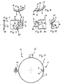
- FIGS. 1 to 10 it is shown that the clamp ends facing away from the joint 1 and angled radially outwards of the clamp brackets 2, 3 are each designed as a mounting flange which can be connected by means of a screw connection 13 for clamping the pipe.
- a connecting element 14 also engages the screw connection 13, with which the pipe clamp 4 according to FIGS. 1 to 10 on the structure can be attached.
- a nut 15 is welded to the clamp bracket 3 and is arranged at a distance from the clamp ends of the clamp bracket 2, 3.
- the pipe clamp 4 shown in FIG. 11 has no sound insulation insert and also no radially inwardly bent clamp edges 10, 11, it is otherwise designed like the pipe clamp 4 according to FIGS. 1 to 10.
- the pipe clamp 4 shown in FIGS. 12 to 19 has a joint 1, the joint parts 5, 7 of which are angled radially outwards.
- the joint parts are either designed as an approximately V-shaped or preferably U-shaped joint opening 5 or have a cross bar 16. Since in the opened state of the clamp brackets 2, 3 the joint parts 5, 7 do not protrude inwards to the inside of the clamp and thus cannot hit the pipe, damage to the pipe encompassed by the pipe clamp 4 as a result of the joint parts 5, 7 is avoided with certainty.
- the clamp brackets 2, 3 can also be very easily connected to one another at their joint parts 5, 7.
- the joint parts 5, 7 are inserted into one another in a simple translational movement in order to subsequently bend the bolt ends of the cross bolt 16 and / or the securing tab 9 delimited by the joint opening 5 such that the second joint part 7 in the region of the cross-sectional constriction 6 cannot be lost in the joint opening 5 is held.
- the outwardly projecting joint parts 5, 7 in the pipe clamp according to FIGS. 12 to 19 can of course also be made considerably shorter, as was shown in FIG. 12, for example. It is also possible to make the joint parts 5, 7 somewhat narrower in comparison to the adjoining partial areas of the clamp brackets 2, 3, so that the C-shaped clamp insert 12 has an undisturbed course along the clamp brackets 2, 3. Instead, however, the clamp insert 12 could also have corresponding incisions in the region of the joint 1 at the free ends of its C-shape, which receive the interlocking joint parts 5, 7.
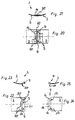
- a joint 1 is shown in FIGS. 20 to 25, the joint parts 5, 7 of which are also each provided on one of the clamp halves 2, 3 of a pipe clamp not shown here. While one clamp half 2 has a first joint part 5 designed as a joint opening, a second joint part 7 is provided at the adjacent clamp end of the other clamp half 3, which has a web-shaped section 6 that introduces into the first joint part. This web-shaped section 6 which can be inserted into the first joint part 2 consists of two webs which connect the second clamp half 3 to a cross bar 16.
- the first joint part 5, for example shown in FIGS. 21 and 23, has offsets or recesses 20 on the visible side in its partial area engaging the clamp bracket 2.
- the middle of the three offsets or recesses 20 on the visible side is engaged by the cross bar 16 of the second hinge part 7.
- offsets or recesses 17 on the visible side of the second joint part in the use position of the joint connection can engage behind the edge region of the clamp bracket 2 which delimits the joint opening 5 and is oriented toward the free end of the first joint part 5.
- the elbows or visible recesses 17, 20 in connection with their counterparts result in a positive connection of these joint parts 5, 7, which causes an increase in the positive locking and thus a practically self-locking connection of these joint parts 5, 7 when the pipe clamp is loaded.
- FIGS. 22 and 23 it is indicated that at the opening edge of the opening 5 at least one, preferably material or securing tabs 9 is (are) provided which can be deformed in the use position of the joint 1 in the direction of the joint opening 5 (cf. dash-dotted lines in Fig. 22).
- the joint opening 5 has a C-shaped shape.
- the cross bar 16 and the webs 6 of the second joint part 7 are adapted to the shape of the cross section of the joint opening 5 for insertion.
- the material or securing tabs 9 are initially angled. After insertion, the material or securing tabs 9 are bent in the direction of the joint opening 5, whereby the two counterparts are captively connected to one another.
- the opening edge, in particular the free webs of the C-shape of the articulated opening 5, are on the one hand and the webs 6 of the second articulated part 7, on the other hand, so adapted in shape that the joint parts 5, 7 are guided into one another essentially without lateral play.
- the edge of the joint opening 5 can also be open. This is to be shown using the example of a further development of the exemplary embodiment according to FIGS. 20 to 25. For this purpose, one can imagine part or all of the edge 21 in FIG. 22 which delimits the workpiece 2 at its end. Although this part 21 no longer exists, the articulated connection can be made captive.
- the material or securing tabs 9 can be attached to the lateral extensions 22 for this purpose, or the extensions 22 are attached alone, i.e. without material or guide tabs 9, so deformed in the direction of the joint opening that the webs 6 of the second joint part are held in a form-fitting manner in the first joint part 5.
- the clamp brackets 2, 3 shown in FIG. 21, for example, also overlap one another in the region of their joint parts 5, 7. This practically eliminates the risk of injury in this area of the pipe clamps according to FIGS. 1 to 11 and FIGS. 20 to 25. This makes these pipe clamps particularly predestined for use in kindergartens, living rooms, etc., where people can come into contact with exposed pipes and pipe clamps.
- the pipe clamp shown in FIGS. 20 to 25 also meets high aesthetic requirements due to its external appearance.
- the pipe clamps shown in Figures 1 to 11 and 20 to 25 in the region of their joint 1 have the advantage that a pipe insulation serving as heat and / or sound insulation can be attached to the clamp brackets 2, 3 without that in the area of Joint 1 notches or similar incisions would be necessary.
Landscapes
- Engineering & Computer Science (AREA)
- General Engineering & Computer Science (AREA)
- Mechanical Engineering (AREA)
- Clamps And Clips (AREA)
- Mutual Connection Of Rods And Tubes (AREA)
Applications Claiming Priority (2)
| Application Number | Priority Date | Filing Date | Title |
|---|---|---|---|
| DE19621098 | 1996-05-24 | ||
| DE1996121098 DE19621098C2 (de) | 1996-05-24 | 1996-05-24 | Gelenkverbindung |
Publications (2)
| Publication Number | Publication Date |
|---|---|
| EP0809060A2 true EP0809060A2 (fr) | 1997-11-26 |
| EP0809060A3 EP0809060A3 (fr) | 1998-04-15 |
Family
ID=7795309
Family Applications (1)
| Application Number | Title | Priority Date | Filing Date |
|---|---|---|---|
| EP97108278A Withdrawn EP0809060A3 (fr) | 1996-05-24 | 1997-05-22 | Raccord articulé pour un collier de serrage |
Country Status (2)
| Country | Link |
|---|---|
| EP (1) | EP0809060A3 (fr) |
| DE (1) | DE19621098C2 (fr) |
Cited By (2)
| Publication number | Priority date | Publication date | Assignee | Title |
|---|---|---|---|---|
| EP0897079A1 (fr) * | 1997-08-11 | 1999-02-17 | Fischerwerke Arthur Fischer GmbH & Co. KG | Collier de serrage pour tuyaux |
| GB2367871A (en) * | 2000-09-15 | 2002-04-17 | Andre Smith | Clamp |
Families Citing this family (1)
| Publication number | Priority date | Publication date | Assignee | Title |
|---|---|---|---|---|
| DE20002579U1 (de) | 2000-02-14 | 2000-06-08 | Rummel, Uwe, 34454 Bad Arolsen | Gelenkverbindung |
Family Cites Families (6)
| Publication number | Priority date | Publication date | Assignee | Title |
|---|---|---|---|---|
| US1473290A (en) * | 1921-07-27 | 1923-11-06 | United Metal Box Co Inc | Hinge structure |
| DE2914080A1 (de) * | 1979-04-07 | 1980-10-16 | Kratzer F Mefa Duebel Gmbh | Rohrschelle |
| DE8902336U1 (de) * | 1989-02-28 | 1989-04-06 | Schulte, Helmut, 5880 Lüdenscheid | Gelenkschraubrohrschelle |
| DE8910177U1 (de) * | 1989-08-25 | 1989-12-28 | Poppe & Co Gießener Gummiwarenfabrik GmbH & Co KG, 6300 Gießen | Einlage für eine Rohrschelle |
| DE4015404C2 (de) * | 1990-03-26 | 1994-01-05 | Maechtle Woehler Margot | Rohrschelle |
| NL9401910A (nl) * | 1994-11-16 | 1996-07-01 | Flamco Bv | Bevestigingsbeugel voor buizen en werkwijze voor het vervaardigen ervan. |
-
1996
- 1996-05-24 DE DE1996121098 patent/DE19621098C2/de not_active Expired - Fee Related
-
1997
- 1997-05-22 EP EP97108278A patent/EP0809060A3/fr not_active Withdrawn
Cited By (3)
| Publication number | Priority date | Publication date | Assignee | Title |
|---|---|---|---|---|
| EP0897079A1 (fr) * | 1997-08-11 | 1999-02-17 | Fischerwerke Arthur Fischer GmbH & Co. KG | Collier de serrage pour tuyaux |
| GB2367871A (en) * | 2000-09-15 | 2002-04-17 | Andre Smith | Clamp |
| GB2367871B (en) * | 2000-09-15 | 2004-06-23 | Andre Smith | Clamp |
Also Published As
| Publication number | Publication date |
|---|---|
| DE19621098A1 (de) | 1997-11-27 |
| EP0809060A3 (fr) | 1998-04-15 |
| DE19621098C2 (de) | 1998-07-02 |
Similar Documents
| Publication | Publication Date | Title |
|---|---|---|
| DE4401746C2 (de) | T Mutter | |
| EP0523518B1 (fr) | Anneau de bride | |
| EP2443352B1 (fr) | Système de liaison de barres profilées | |
| DE29909715U1 (de) | Wellschlauch mit einer Halterung | |
| EP3839275B1 (fr) | Pince de maintien d'une fermeture rapide, fermeture rapide ainsi que raccord de composant doté d'une telle fermeture rapide | |
| WO2015117763A1 (fr) | Bride de fixation | |
| DE3742737A1 (de) | Schutzzylinder fuer ein ummantelungsmaterial fuer ein rohr | |
| DE69418657T2 (de) | Bauelement | |
| DE19621098C2 (de) | Gelenkverbindung | |
| DE69326483T2 (de) | Konstruktionsverbindung | |
| DE69506887T2 (de) | Befestigungsring | |
| DE19900154A1 (de) | Klammer | |
| DE29619144U1 (de) | Trägerklammer | |
| DE19835320B4 (de) | Rohrschelle | |
| DE202008008250U1 (de) | Eckverbinder | |
| DE8701832U1 (de) | Scharnierelement | |
| EP0438046B1 (fr) | Pièce d'assemblage d'angle pour dormants | |
| DE69509275T2 (de) | Rohraufhängevorrichtung | |
| DE29720907U1 (de) | Verbindung von Bauelementen mittels Dreh-/Spannverschlüssen | |
| DE69925404T2 (de) | Metallische Verbindungsvorrichtung und Beschlagteile dafür | |
| DE19853988C1 (de) | Befestigungsvorrichtung | |
| CH652188A5 (en) | Composite profile | |
| EP1024303B1 (fr) | Elément de fixation pour tige filetée | |
| DE9205320U1 (de) | Befestigungskonstruktion | |
| DE3309965A1 (de) | Spannbuegel |
Legal Events
| Date | Code | Title | Description |
|---|---|---|---|
| PUAI | Public reference made under article 153(3) epc to a published international application that has entered the european phase |
Free format text: ORIGINAL CODE: 0009012 |
|
| AK | Designated contracting states |
Kind code of ref document: A2 Designated state(s): AT CH DE LI NL |
|
| DAX | Request for extension of the european patent (deleted) | ||
| PUAL | Search report despatched |
Free format text: ORIGINAL CODE: 0009013 |
|
| AK | Designated contracting states |
Kind code of ref document: A3 Designated state(s): AT CH DE LI NL |
|
| STAA | Information on the status of an ep patent application or granted ep patent |
Free format text: STATUS: THE APPLICATION IS DEEMED TO BE WITHDRAWN |
|
| 18D | Application deemed to be withdrawn |
Effective date: 19981016 |