EP0809061B1 - Dispositif de traversée d'un élément allongée au travers d'une ouverture dans une paroi - Google Patents
Dispositif de traversée d'un élément allongée au travers d'une ouverture dans une paroi Download PDFInfo
- Publication number
- EP0809061B1 EP0809061B1 EP97400976A EP97400976A EP0809061B1 EP 0809061 B1 EP0809061 B1 EP 0809061B1 EP 97400976 A EP97400976 A EP 97400976A EP 97400976 A EP97400976 A EP 97400976A EP 0809061 B1 EP0809061 B1 EP 0809061B1
- Authority
- EP
- European Patent Office
- Prior art keywords
- rubber sleeve
- wall
- opening
- cable
- plate
- Prior art date
- Legal status (The legal status is an assumption and is not a legal conclusion. Google has not performed a legal analysis and makes no representation as to the accuracy of the status listed.)
- Expired - Lifetime
Links
- 238000007789 sealing Methods 0.000 claims description 11
- 239000013013 elastic material Substances 0.000 claims description 4
- 239000000463 material Substances 0.000 claims description 3
- 230000002093 peripheral effect Effects 0.000 claims 4
- 230000035515 penetration Effects 0.000 claims 2
- 238000000926 separation method Methods 0.000 description 3
- 125000000484 butyl group Chemical group [H]C([*])([H])C([H])([H])C([H])([H])C([H])([H])[H] 0.000 description 2
- 150000001875 compounds Chemical class 0.000 description 2
- 238000010276 construction Methods 0.000 description 2
- 230000001681 protective effect Effects 0.000 description 2
- 229910000831 Steel Inorganic materials 0.000 description 1
- 230000000694 effects Effects 0.000 description 1
- 230000037431 insertion Effects 0.000 description 1
- 238000003780 insertion Methods 0.000 description 1
- 239000004033 plastic Substances 0.000 description 1
- 239000010959 steel Substances 0.000 description 1
Images


Classifications
-
- H—ELECTRICITY
- H02—GENERATION; CONVERSION OR DISTRIBUTION OF ELECTRIC POWER
- H02G—INSTALLATION OF ELECTRIC CABLES OR LINES, OR OF COMBINED OPTICAL AND ELECTRIC CABLES OR LINES
- H02G3/00—Installations of electric cables or lines or protective tubing therefor in or on buildings, equivalent structures or vehicles
- H02G3/22—Installations of cables or lines through walls, floors or ceilings, e.g. into buildings
-
- F—MECHANICAL ENGINEERING; LIGHTING; HEATING; WEAPONS; BLASTING
- F16—ENGINEERING ELEMENTS AND UNITS; GENERAL MEASURES FOR PRODUCING AND MAINTAINING EFFECTIVE FUNCTIONING OF MACHINES OR INSTALLATIONS; THERMAL INSULATION IN GENERAL
- F16L—PIPES; JOINTS OR FITTINGS FOR PIPES; SUPPORTS FOR PIPES, CABLES OR PROTECTIVE TUBING; MEANS FOR THERMAL INSULATION IN GENERAL
- F16L5/00—Devices for use where pipes, cables or protective tubing pass through walls or partitions
- F16L5/02—Sealing
- F16L5/10—Sealing by using sealing rings or sleeves only
Definitions
- the invention relates to a device for performing an elongated Object through an opening in a wall, with a flat plate attached to the wall stable material that corresponds to the opening and is flush with it Breakthrough, and with one attached around the elongated object Sealing serving arrangement, which is in mounting position with the plate is connected (assembly instructions HTT 54.003-02 from RFS Hannover, edition 8/95).
- “Elongated object” in the sense of the invention can be pipes and electrical cables be, especially high frequency cables.
- the following is for all possible items the short term “cable” is used as a representative.
- the cables usually have one outer protective jacket made of plastic. Your soul is therefore protected against moisture, as long as the protective jacket is not damaged.
- the demand for effective protection against moisture also exists for the area where the cable is passed through Wall when it is led into a building. The opening in the wall has to Assembly of the cable must be so tightly closed that no moisture enters it through it Building can enter.
- the invention is based on the object, the device described in construction and Simplify handling.
- the rubber sleeve is made in one piece. For sealing the entry point of a Therefore, only a part of the cable in a building needs to be installed, if the ring-shaped insert is pre-assembled in the rubber sleeve has been. This is the construction of the whole for sealing the entry point used device significantly simplified. Also the assembly of the rubber sleeve itself is easy. It only needs after laying around the cable with one end in it Perforation of the plate to be pressed until its edge area all the way into the Recess engages. The rubber sleeve is then closed, for example screwed. It is moisture-proof connected to the plate and the cable is through the Inlay enclosed moisture-proof.
- Fig. 1 shows a schematic representation of a wall bushing with a device according to the Invention.
- Fig. 2 shows a section through Fig. 1 along the line II - II.
- Fig. 3 is an end view of a rubber sleeve usable in the device.
- Fig. 4 shows a section through Fig. 3 along the line IV - IV.
- Fig. 5 is a view of an insert usable in the rubber sleeve.
- Fig. 6 shows a section through Fig. 5 along the line VI - VI.
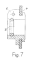
- Fig. 7 is a view of an assembled rubber sleeve without a cable.
- the wall of a building is designated, into which a cable 2 protrudes.
- This is in the Wall 1 has an opening 3 attached.
- a wall 1 on the outside mechanically stable, for example made of steel plate 4 mounted one with the Opening 3 has aligned opening 5.
- cable 2 is from a rubber sleeve 6 enclosed, the moisture-proof on the cable 2 on the one hand and on the Plate 4 on the other hand.
- FIGS. 3 to 7. The more precise structure of the rubber sleeve 6 and its assembly at the point of insertion of the cable 2 into the wall 1 are shown in FIGS. 3 to 7.
- the rubber sleeve 6 is made in one piece. It is at a separation point 7 in the longitudinal direction divided so that it can be placed around the cable 2. The area of the separation point 7 also serves to close the rubber sleeve 6. It is expanded accordingly so that for example, at least one screw 8 can be attached therein. The Rubber sleeve 6 can then be closed by means of a screw connection. But it can also be locked in another way. For example, by a snap connection.
- the rubber sleeve 6 In its inner surface, the rubber sleeve 6 has a circumferential groove 9, in which an evident from FIGS. 5 and 6, annular insert 10 made of elastic material can be used.
- the rubber sleeve 6 with the insert 10 located therein can be seen in FIG. 7.
- the interior of the rubber sleeve 6 is shown in FIG. 4 at one end to the outside flared. The oblique trailing edge thus formed ensures that in this Area of the rubber sleeve 6 no moisture can accumulate.
- the rubber collar 6 is on the outside a circumferential recess 11 is attached. It serves to seal the edge of the Plate 4 when the rubber sleeve 6 is inserted into the opening 5. This The mounting position of the rubber sleeve 6 is shown in FIG. 7.
- the rubber sleeve 6 lies sealing on both sides of the plate 4.
- an additional sealing element in the recess 11 before assembly of the rubber sleeve 6 be attached, for example a ring made of a butyl sealing compound.
- the insert 10 is made of an elastic material, for example a rubber. She must be relatively easy to compress to optimally function as a sealing body correspond.
- the insert 10 has a separation point 12 in a preferred embodiment, so that it as well as the rubber sleeve 6 and preferably with the same in the radial direction the cable 2 can be put on.
- the Insert 10 at one axial end of a reduced symmetrical to the central axis light To be wide. This can be seen from FIGS. 6 and 7.
- rubber sleeve 6 and insert 10 enclose one circular interior.
- This interior can also have a different clear cross section to have. It can be elliptical, for example. This is an advantage if cable 2 is on is elliptical electromagnetic waveguide.
- the device according to the invention is handled, for example, as follows:
- the plate 4 After completion of the opening 3 in the wall 1, the plate 4 is mounted on the same. Then the cable 2 is pulled so far that a sufficient length of the same in the building bounded by wall 1 protrudes.
- the rubber sleeve 6 is opened sideways the cable 2 placed and moved in the axial direction to the plate 4. By simultaneous The end of the rubber sleeve 6 will rotate and press in the opening 5 of the plate 4 brought into a position shown in FIG. 7. Then the insert 10 is also sideways placed on the cable 2 and pushed axially into the rubber sleeve 6 until it is in accordance with Fig. 7 lies in the groove 9. Finally, the rubber sleeve 6 by tightening the Screw 8 closed. The insert 10 is pressed firmly against the cable 2.
Landscapes
- Engineering & Computer Science (AREA)
- General Engineering & Computer Science (AREA)
- Architecture (AREA)
- Civil Engineering (AREA)
- Structural Engineering (AREA)
- Mechanical Engineering (AREA)
- Installation Of Indoor Wiring (AREA)
- Control And Other Processes For Unpacking Of Materials (AREA)
Claims (6)
- Dispositif de passage d'un objet très allongé (2) à travers un orifice ménagé dans un mur (1) grâce à une plaque plane (4) en matériau solide fixée au mur et possédant un orifice (5) parfaitement aligné sur l'orifice du mur (1) et dotée d'une structure (6) disposée sur tout le pourtour de l'objet très allongé (2), servant à l'étanchéité et reliée à la plaque (4) en position de montage, selon lequelle dispositif d'étanchéité est conçu sous la forme d'un manchon en caoutchouc (6) d'un seul tenant et présentant une fente séparatrice (7) dans le sens longitudinal au niveau de laquelle il peut être fermé,un insert annulaire (10) en matériau élastique est introduit dans la rainure périphérique (9) aménagée sur la face intérieure spécifique du manchon en caoutchouc (6) destiné à s'adapter sur l'objet très allongé (2) etle manchon en caoutchouc (6) présente au niveau d'une extrémité axiale externe un renfoncement (11) périphérique orienté vers l'extérieur pour application étroite sur le bord séparateur de la plaque (4) en contact avec l'orifice de passage (5).
- Dispositif selon l'exigence 1 caractérisé par le fait que le diamètre interne de l'insert (10) est réduit à son extrémité axiale de manière symétrique à l'axe médian.
- Dispositif selon exigence 1 ou 2, caractérisé par le fait que le manchon en caoutchouc (6) peut être fermé par raccord vissé.
- Dispositif selon exigence 1 ou 2 caractérisé par le fait que le manchon en caoutchouc (6) peut être fermé au moyen d'un assemblage à enclenchement.
- Dispositif selon l'une des exigences 1 à 4 caractérisé par le fait qu'un élément d'étanchéité est placé à l'intérieur du renfoncement (11) périphérique.
- Dispositif selon l'une des exigences 1 à 5, caractérisé par le fait que l'espace interne du manchon en caoutchouc (6) est élargi vers l'extérieur de manière conique au niveau de l'extrémité tournée vers le renfoncement périphérique (11)
Applications Claiming Priority (2)
| Application Number | Priority Date | Filing Date | Title |
|---|---|---|---|
| DE29609416U | 1996-05-25 | ||
| DE29609416U DE29609416U1 (de) | 1996-05-25 | 1996-05-25 | Vorrichtung zur Durchführung eines langgestreckten Gegenstandes durch eine Öffnung einer Wand |
Publications (2)
| Publication Number | Publication Date |
|---|---|
| EP0809061A1 EP0809061A1 (fr) | 1997-11-26 |
| EP0809061B1 true EP0809061B1 (fr) | 2001-01-10 |
Family
ID=8024442
Family Applications (1)
| Application Number | Title | Priority Date | Filing Date |
|---|---|---|---|
| EP97400976A Expired - Lifetime EP0809061B1 (fr) | 1996-05-25 | 1997-04-30 | Dispositif de traversée d'un élément allongée au travers d'une ouverture dans une paroi |
Country Status (4)
| Country | Link |
|---|---|
| US (1) | US5950381A (fr) |
| EP (1) | EP0809061B1 (fr) |
| BR (1) | BR9703317A (fr) |
| DE (2) | DE29609416U1 (fr) |
Families Citing this family (19)
| Publication number | Priority date | Publication date | Assignee | Title |
|---|---|---|---|---|
| CH693151A5 (de) * | 1998-10-29 | 2003-03-14 | Pma Ag | Verbindungs- und Anschlussstück für Wellrohre. |
| US6305425B1 (en) * | 1999-08-02 | 2001-10-23 | Doris Korn | Pipe leadthrough |
| US7407165B1 (en) * | 2000-04-04 | 2008-08-05 | Hutchinson Fts, Inc. | Composite sleeve for sealing a tubular coupling |
| US7024824B1 (en) | 2003-09-04 | 2006-04-11 | Felix Widlacki | Entry port |
| US7244085B2 (en) * | 2004-04-26 | 2007-07-17 | Illinois Tool Works, Inc | Fastener assembly |
| DE102006025704B3 (de) * | 2006-06-01 | 2007-12-20 | Siemens Ag | Verfahren und Vorrichtung zum Betätigen einer Parkbremse |
| DE102006026222A1 (de) * | 2006-06-06 | 2007-12-13 | Siemens Ag | Fahrtschreiber für ein Kraftfahrzeug |
| US7770742B1 (en) * | 2007-10-18 | 2010-08-10 | George Wagner | Shower caddy |
| DE102010018677A1 (de) * | 2010-04-28 | 2011-11-03 | Watermann Polyworks Gmbh | Dichtungsmanschette |
| US8944718B2 (en) | 2010-09-23 | 2015-02-03 | C-Flex Bearing Co., Inc. | Clamping bushing |
| US8973216B1 (en) * | 2011-09-01 | 2015-03-10 | Ralph M. Ramirez | Grommet |
| US10488074B2 (en) | 2011-09-09 | 2019-11-26 | Capital Hardware Supply, Inc. | Airtight bushing for ductwork damper and the like and ductwork damper unit incorporating same |
| CN102829182B (zh) * | 2012-08-09 | 2015-01-21 | 北京七星华创电子股份有限公司 | 用于运动管件和固定平板连接处的密封装置 |
| EP3464975A1 (fr) | 2016-06-06 | 2019-04-10 | Spider Clip L.L.C. | Dispositif de retenue destiné à un tuyau d'eau |
| DE202018002655U1 (de) * | 2018-06-05 | 2019-09-06 | Hauff-Technik Gmbh & Co. Kg | Flansch zum Montieren auf einer Leitung |
| US11053687B1 (en) * | 2018-10-25 | 2021-07-06 | Justin Oser | Fascia saver device and system |
| US11199286B1 (en) * | 2019-10-04 | 2021-12-14 | Evergreen Tool Company, Inc. | Bushing shield for fire detection |
| IL301465B1 (en) * | 2022-02-01 | 2026-04-01 | Inan Makina Sanayi Ve Ticaret Anonim Sirketi | Vibration reduction device |
| EP4244023A4 (fr) * | 2022-02-01 | 2024-11-20 | Inan Makina Sanayi Ve Ticaret Anonim Sirketi | Appareil amortisseur de vibrations |
Family Cites Families (16)
| Publication number | Priority date | Publication date | Assignee | Title |
|---|---|---|---|---|
| US1243748A (en) * | 1914-07-03 | 1917-10-23 | Adnah Mcmurtrie | Connector for electrical conduits. |
| US2311427A (en) * | 1941-07-18 | 1943-02-16 | Gen Motors Corp | Grommet |
| US2897533A (en) * | 1956-02-16 | 1959-08-04 | Gen Motors Corp | Grommets, bushings and the like |
| US4033535A (en) * | 1973-05-18 | 1977-07-05 | Eaton Corporation | Strain-relief bushing |
| FR2406903A1 (fr) * | 1977-10-18 | 1979-05-18 | Morel Atel Electromec | Procede pour realiser une liaison etanche entre un cable telephonique ou analogue et une canalisation et manchon s'y rapportant |
| US4640479A (en) * | 1983-01-31 | 1987-02-03 | All States Inc. | Strain relief grommet |
| DE3430902A1 (de) * | 1984-08-22 | 1986-03-06 | Bosch-Siemens Hausgeräte GmbH, 7000 Stuttgart | Durchfuehrungen durch wandungen von druckbehaeltern |
| ES2000411A4 (es) * | 1986-03-21 | 1988-03-01 | Agintec Ag | Junta de obturacion. |
| DE9006915U1 (de) * | 1990-06-20 | 1990-08-23 | Peter Lancier Maschinenbau-Hafenhütte GmbH & Co KG, 48167 Münster | Abdichtring |
| JPH0722993Y2 (ja) * | 1990-09-27 | 1995-05-24 | 誠新産業株式会社 | 地中ケーブルの配線構造 |
| US5442140A (en) * | 1993-10-05 | 1995-08-15 | Homac Mfg. Company | Conduit and cable sealer |
| JPH0741881U (ja) * | 1993-12-27 | 1995-07-21 | 住友電装株式会社 | ワイヤハーネス用グロメット |
| US5739475A (en) * | 1994-04-21 | 1998-04-14 | Inoac Corporation | Grommet for protecting a wire harness with structure for ensuring flush seating |
| US5575487A (en) * | 1995-01-17 | 1996-11-19 | Bal Seal Engineering Company, Inc. | Circular tapered ring for static sealing under conditions of high pressure |
| JP2946296B2 (ja) * | 1995-12-06 | 1999-09-06 | 矢崎総業株式会社 | サイレンサー付グロメット及びその取付構造 |
| EP0823763B1 (fr) * | 1996-08-09 | 1999-11-03 | Sumitomo Wiring Systems, Ltd. | Douille de traversée |
-
1996
- 1996-05-25 DE DE29609416U patent/DE29609416U1/de not_active Expired - Lifetime
-
1997
- 1997-04-17 US US08/840,889 patent/US5950381A/en not_active Expired - Fee Related
- 1997-04-30 DE DE59702876T patent/DE59702876D1/de not_active Expired - Fee Related
- 1997-04-30 EP EP97400976A patent/EP0809061B1/fr not_active Expired - Lifetime
- 1997-05-26 BR BR9703317A patent/BR9703317A/pt active Search and Examination
Also Published As
| Publication number | Publication date |
|---|---|
| US5950381A (en) | 1999-09-14 |
| BR9703317A (pt) | 1998-09-15 |
| DE29609416U1 (de) | 1996-08-14 |
| EP0809061A1 (fr) | 1997-11-26 |
| DE59702876D1 (de) | 2001-02-15 |
Similar Documents
| Publication | Publication Date | Title |
|---|---|---|
| EP0809061B1 (fr) | Dispositif de traversée d'un élément allongée au travers d'une ouverture dans une paroi | |
| EP2382693B1 (fr) | Dispositif de fixation pour fixer un câble sur un passage de boîtier | |
| EP2323228B1 (fr) | Boîtier de connecteur doté d'un élément coudé de reprise des contraintes | |
| DE69111103T2 (de) | Elektrischer Verbinder für flüssigkeitsdichte Röhre. | |
| DE3218677C2 (de) | Elektrische Steckverbinderanordnung | |
| DE19738733C1 (de) | Steckverbinder für Koaxialkabel mit ringgewelltem Außenleiter | |
| AT519366B1 (de) | Anschlussgehäuse und anschlusssystem | |
| DE3141966A1 (de) | "anschlussvorrichtung fuer koaxialkabel" | |
| DE9110007U1 (de) | Kabeldurchführungsvorrichtung | |
| EP0392089B1 (fr) | Dispositif de fermeture d'une extrémité de câble | |
| DE4129293C1 (en) | Coaxial antenna socket for wall or flush mounting - accepts cables for radio, TV and satellite set in internal lead running parallel with axis of housing so that support wall does not require place for connections | |
| DE19857340C2 (de) | Kabelverschraubung für Kabel mit Abschirmummantelung | |
| DE102008046658B4 (de) | Kabeldurchführung | |
| DE4403571C1 (de) | Verbindungsmuffe für kunststoffisolierte Hochspannungsenergieversorgungskabel | |
| WO2006069786A1 (fr) | Dispositif mesureur de distance parcourue | |
| EP1740903A2 (fr) | Dispositif de mesure de deplacement | |
| EP0640786B1 (fr) | Raccord à vis combiné pour câble et tuyau souple | |
| DE3433631C2 (fr) | ||
| DE2851864C2 (de) | Anschlußeinrichtung für Koaxialkabel | |
| DE2330320B2 (de) | HF-Koaxialkabelarmatur | |
| DE102021200861A1 (de) | Vorrichtung zum abgedichteten Durchführen eines länglichen Strangs | |
| DE20113219U1 (de) | Einrichtung zum elektrisch leitenden Kontaktieren eines abschnittsweise abisolierten Außenleiters eines Koaxialkabels | |
| DE3300809A1 (de) | Kabelendverschraubung | |
| DE29909414U1 (de) | Lüftungseinheit | |
| DE20017583U1 (de) | Durchführungsarmatur für ein Kabel oder Rohr |
Legal Events
| Date | Code | Title | Description |
|---|---|---|---|
| PUAI | Public reference made under article 153(3) epc to a published international application that has entered the european phase |
Free format text: ORIGINAL CODE: 0009012 |
|
| 17P | Request for examination filed |
Effective date: 19970906 |
|
| AK | Designated contracting states |
Kind code of ref document: A1 Designated state(s): BE DE FI FR GB IT |
|
| RAP1 | Party data changed (applicant data changed or rights of an application transferred) |
Owner name: ALCATEL |
|
| GRAG | Despatch of communication of intention to grant |
Free format text: ORIGINAL CODE: EPIDOS AGRA |
|
| 17Q | First examination report despatched |
Effective date: 20000316 |
|
| GRAG | Despatch of communication of intention to grant |
Free format text: ORIGINAL CODE: EPIDOS AGRA |
|
| GRAH | Despatch of communication of intention to grant a patent |
Free format text: ORIGINAL CODE: EPIDOS IGRA |
|
| GRAH | Despatch of communication of intention to grant a patent |
Free format text: ORIGINAL CODE: EPIDOS IGRA |
|
| GRAA | (expected) grant |
Free format text: ORIGINAL CODE: 0009210 |
|
| AK | Designated contracting states |
Kind code of ref document: B1 Designated state(s): BE DE FI FR GB IT |
|
| ITF | It: translation for a ep patent filed | ||
| ET | Fr: translation filed | ||
| GBT | Gb: translation of ep patent filed (gb section 77(6)(a)/1977) |
Effective date: 20010110 |
|
| REF | Corresponds to: |
Ref document number: 59702876 Country of ref document: DE Date of ref document: 20010215 |
|
| PLBE | No opposition filed within time limit |
Free format text: ORIGINAL CODE: 0009261 |
|
| STAA | Information on the status of an ep patent application or granted ep patent |
Free format text: STATUS: NO OPPOSITION FILED WITHIN TIME LIMIT |
|
| REG | Reference to a national code |
Ref country code: GB Ref legal event code: IF02 |
|
| 26N | No opposition filed | ||
| PGFP | Annual fee paid to national office [announced via postgrant information from national office to epo] |
Ref country code: GB Payment date: 20020402 Year of fee payment: 6 Ref country code: FI Payment date: 20020402 Year of fee payment: 6 |
|
| PGFP | Annual fee paid to national office [announced via postgrant information from national office to epo] |
Ref country code: BE Payment date: 20020412 Year of fee payment: 6 |
|
| PGFP | Annual fee paid to national office [announced via postgrant information from national office to epo] |
Ref country code: FR Payment date: 20020416 Year of fee payment: 6 |
|
| PGFP | Annual fee paid to national office [announced via postgrant information from national office to epo] |
Ref country code: DE Payment date: 20020418 Year of fee payment: 6 |
|
| PG25 | Lapsed in a contracting state [announced via postgrant information from national office to epo] |
Ref country code: GB Free format text: LAPSE BECAUSE OF NON-PAYMENT OF DUE FEES Effective date: 20030430 Ref country code: FI Free format text: LAPSE BECAUSE OF NON-PAYMENT OF DUE FEES Effective date: 20030430 Ref country code: BE Free format text: LAPSE BECAUSE OF NON-PAYMENT OF DUE FEES Effective date: 20030430 |
|
| BERE | Be: lapsed |
Owner name: *ALCATEL Effective date: 20030430 |
|
| PG25 | Lapsed in a contracting state [announced via postgrant information from national office to epo] |
Ref country code: DE Free format text: LAPSE BECAUSE OF NON-PAYMENT OF DUE FEES Effective date: 20031101 |
|
| GBPC | Gb: european patent ceased through non-payment of renewal fee | ||
| PG25 | Lapsed in a contracting state [announced via postgrant information from national office to epo] |
Ref country code: FR Free format text: LAPSE BECAUSE OF NON-PAYMENT OF DUE FEES Effective date: 20031231 |
|
| REG | Reference to a national code |
Ref country code: FR Ref legal event code: ST |
|
| PG25 | Lapsed in a contracting state [announced via postgrant information from national office to epo] |
Ref country code: IT Free format text: LAPSE BECAUSE OF NON-PAYMENT OF DUE FEES Effective date: 20050430 |