EP0809069A1 - Rücklaufzerstäuberdüse - Google Patents
Rücklaufzerstäuberdüse Download PDFInfo
- Publication number
- EP0809069A1 EP0809069A1 EP96941172A EP96941172A EP0809069A1 EP 0809069 A1 EP0809069 A1 EP 0809069A1 EP 96941172 A EP96941172 A EP 96941172A EP 96941172 A EP96941172 A EP 96941172A EP 0809069 A1 EP0809069 A1 EP 0809069A1
- Authority
- EP
- European Patent Office
- Prior art keywords
- return
- core
- penetrating hole
- spray nozzle
- distributor
- Prior art date
- Legal status (The legal status is an assumption and is not a legal conclusion. Google has not performed a legal analysis and makes no representation as to the accuracy of the status listed.)
- Withdrawn
Links
Images


Classifications
-
- F—MECHANICAL ENGINEERING; LIGHTING; HEATING; WEAPONS; BLASTING
- F23—COMBUSTION APPARATUS; COMBUSTION PROCESSES
- F23D—BURNERS
- F23D11/00—Burners using a direct spraying action of liquid droplets or vaporised liquid into the combustion space
- F23D11/36—Details
- F23D11/38—Nozzles; Cleaning devices therefor
- F23D11/383—Nozzles; Cleaning devices therefor with swirl means
-
- F—MECHANICAL ENGINEERING; LIGHTING; HEATING; WEAPONS; BLASTING
- F23—COMBUSTION APPARATUS; COMBUSTION PROCESSES
- F23D—BURNERS
- F23D11/00—Burners using a direct spraying action of liquid droplets or vaporised liquid into the combustion space
- F23D11/24—Burners using a direct spraying action of liquid droplets or vaporised liquid into the combustion space by pressurisation of the fuel before a nozzle through which it is sprayed by a substantial pressure reduction into a space
- F23D11/26—Burners using a direct spraying action of liquid droplets or vaporised liquid into the combustion space by pressurisation of the fuel before a nozzle through which it is sprayed by a substantial pressure reduction into a space with provision for varying the rate at which the fuel is sprayed
- F23D11/28—Burners using a direct spraying action of liquid droplets or vaporised liquid into the combustion space by pressurisation of the fuel before a nozzle through which it is sprayed by a substantial pressure reduction into a space with provision for varying the rate at which the fuel is sprayed with flow-back of fuel at the burner, e.g. using by-pass
Definitions
- the present invention relates to a return type spray nozzle, more detailedly to the return type spray nozzle suitably usable for such liquid fuel burners as home hotwater and heating appliances with comparatively small burning capability and with the needs of fine, accurate, and large turndown ratio.
- a return type spray nozzle is a nozzle that sprays out the liquid fuel coming to a return type spray nozzle 4 through a supply line 3 by means of a pump 2 attached to a tank 1 for the use of burning, and at the same time, sends a part of the liquid fuel back to a return path 5 without spraying.
- the liquid fuel returned to the return path 5 is returned to the tank 1 and the like as shown in Fig.11, or, on the way, is made again to circulate to the inlet side of the pump 2 on the supply line 3.
- the return amount is adjusted by a return amount control valve 6.
- said usual return type spray nozzle has a spray nozzle body 10 and a distributor 20 inserted into the inner hole 11 of the spray nozzle body 10.
- a spray opening 12 is provided at the center of the top part of the spray nozzle body 10.
- a return aperture 21 that penetrates the center of the top flat surface 25 of the distributor 20, and plurality of fuel supplying slit-ducts 23 that are formed at the shoulder part 22 of the distributor 20 that contacts with the inner hole 11 of said spray nozzle body 10.
- the liquid fuel sent out of the pump 2 enters a spray waiting chamber 30 via the inner holes 11 in the spray nozzle body 10 and via said fuel supplying slit-ducts 23, and then sprays out of the spray opening 12. Part of the above liquid fuel is returned from the spray waiting chamber 30 through the return aperture 21.
- the position of the return aperture 21 of the distributor 20 and the position of the spray opening 12 of the spray nozzle body 10 may fall in the same axis, and also, the center of the revolving vortex produced by the mighty liquid fuel introduced into the spray waiting chamber 30 through said plurality of slit-ducts 23 may fall in the return aperture 21.
- the center of the revolving vortex produced by the mighty liquid fuel introduced into the spray waiting chamber 30 through said plurality of slit-ducts 23 may fall in the return aperture 21.
- Figs.13 and 14 show the constitution of that invention.
- Fig.13 is a vertical sectional and structural view of the principal part of the nozzle
- Fig.14 is a plan view of the distributor 20.
- return apertures 24 that penetrate the top thickness of the distributor 20 are provided.
- Plurality of the return apertures 24 are provided in symmetrical arrangement around the center axis X ( 2 apertures in Figs. 13 and 14 ). Generally, in Figs. 13 and 14, the same part materials, parts, and elements as those explained in Fig.12 are shown with the same symbols.
- the present invention aims at providing such a return type spray nozzle as enabling to solve said existing problem and to obtain small return apertures at the locations deviated from the center axis of the spray opening securely, easily and at a low cost, thereby enabling to prevent external air from being involved in return apertures and obtaining fine, accurate and large turndown ratio at small capacity burning.
- the return type spray nozzle of the present invention consists essentially of a spray nozzle body and a distributor inserted into the inner hole of said spray nozzle body, the center of the top part of said spray nozzle body being equipped with a spray opening, the vicinity of the center of the top part of said distributor being equipped with return apertures at the locations deviated from the center axis of said spray opening, the outside of the shoulder part of said distributor being equipped with fuel supplying slit-ducts that supply liquid fuel sent into the inner hole in said spray nozzle body to a spray waiting chamber located in front of the top part of said distributor, said liquid fuel sent into said spray waiting chamber then being blown out through said spray opening from the spray waiting chamber, at the same time part of said liquid fuel in said spray waiting chamber being made to return through said return apertures instead of being blown out through said spray opening, said return apertures of said distributor being formed as penetrating gaps created at the boundary area between a central penetrating hole and a core-body that is inserted rigidly into the central
- the return type spray nozzle of the present invention makes it the second feature that the return apertures are formed as penetrating gaps created at the boundary area between the central penetrating hole and the core-body, by that the core-body whose outside surface is concavely and multiplicately striped is inserted rigidly into the central penetrating hole.
- the return type spray nozzle of the present invention makes it the third feature that the return apertures, by concave stripes, are formed as penetrating gaps created at the boundary area between the central penetrating hole and the core-body, by that the core-body is inserted rigidly into the central penetrating hole whose inside surface is concavely and multiplicately striped.
- the return type spray nozzle of the present invention makes it the fourth feature that the plurality of return apertures are arranged symmetrically around the center axis.
- the return type spray nozzle of the present invention makes it the fifth feature that a ring-shaped return aperture is formed as a penetrating gap at the boundary area between the core-body and the central penetrating hole, by that the core-body that has the similar-figure and smaller diameter, as compared with the central penetrating hole, is inserted rigidly into the central penetrating hole.
- the return apertures are formed as penetrating gaps created at the boundary area between the central penetrating hole that is formed in the vicinity of the center of the top part of the distributor coaxially with the center axis of the spray opening and the core-body that is inserted into the central penetrating hole with its incoordinate sectional shape ; namely the return apertures are formed as penetrating gaps created on account of the different sectional shapes ; so that small diametrical return apertures can be formed easily at the locations deviated from the center axis.
- the diameters of said central penetrating hole and the core-body themselves can be made to be relatively large, drilling process is easy.
- the working for making the sectional shapes of both the central penetrating hole and the core-body incoordinate can be easily done ; namely, the working of longitudinal concave or convex striping, shaving, scratching, pressing inside the central penetrating hole or outside the core-body, can be easily performed. Accordingly, it is possible to form the return apertures at far less difficulty and cost as compared with the case wherein small holes should be directly drilled through the distributor.
- the return apertures can be made to be plural like two, three, and four ; but only one will also do.
- Installing the return apertures being at the positions deviated from the center axis can prevent the air coming from the spray opening and passing through the center part of the vortex flow in the spray waiting chamber from invading the return apertures.
- the adequately small diametrical return apertures can be securely, simply, and easily obtained ; so that, the return apertures can be all the more surely protected from being invaded by the air.
- Inserting the core-body into the central penetrating hole can be performed by the use of, for instance, expansion fit, shrinkage fit, ultrasonic fit, and other known technology.
- the longitudinal concave stripes on core-body outside surface can be formed by scratching, shaving, cutting, and pressing the relevant stripe positions.
- the core body whose outside surface is concavely and multiplicately striped is inserted rigidly into the central penetrating hole ; as a result, the return apertures by the above concave stripes are formed as the penetrating gaps created at the boundary area between the core-body and the central penetrating hole ; resultingly, adequately small diametrical return apertures that are deviated from the center axis can be obtained, the return apertures can be securely protected from being invaded by the air, and at the same time, capability adjustment at small capacity burning can be surely performed.
- the concave stripes of the central penetrating hole inside surface can be formed like the case of the core-body outside surface.
- the core-body is inserted rigidly into the central penetrating hole whose inside surface is concavely and multiplicately striped ; as a result, the return apertures by the above concave stripes are formed as the penetrating gaps created at the boundary area between the core-body and the central penetrating hole ; resultingly, adequately small diametrical return apertures that are deviated from the center axis can be obtained, the return apertures can be securely protected from being invaded by the air, and at the same time, capability adjustment at small capacity burning can be surely performed.
- the plurality of return apertures are installed symmetrically around the center axis. So that, the liquid fuel, from the spray waitng chamber , that is returned to the return apertures becomes well balanced, and as a result, the place-based overs-and-shorts of the liquid fuel in the spray waiting chamber can be removed, and stable spraying from the spray waiting chamber can be performed.
- the small diametrical and ring-shaped return aperture can be obtained at the position deviated from the center axis, and so, the return aperture can be securely protected from being invaded by the air, and at the same time, capability adjustment at small capacity burning can be surely performed.
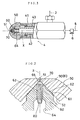
- Fig.1, Fig.2, Fig.3, and Fig.4 show the first preferred embodiment of the present invention ;
- Fig.1 is a partially cutaway side view illustrating the overall outline of the return type spray nozzle
- Fig.2 is a vertical sectional and structural view of the principal part of the return type spray nozzle
- Fig.3 is a plan view of the principal part of the distributor
- Fig.4 is a perspective view of the core-body.
- Fig.5 and Fig.6 show the second preferred embodiment of the present invention ;
- Fig.5 is a plan view of the principal part of the distributor of the return type spray nozzle, and
- Fig.6 is a perspective view of the core-body.
- Fig.7 and Fig.8 show the third preferred embodiment of the present invention ;
- Fig.7 is a vertical sectional and structural view of the principal part of the distributor of the return type spray nozzle, and
- Fig.8 is a plan view of the principal part of the distributor.
- Fig.9 and Fig.10 show the fourth preferred embodiment of the present invention ;
- Fig.9 is a vertical sectional and structural view of the principal part of the distributor of the return type spray nozzle, and
- Fig.10 is a plan view of the distributor of the return type spray nozzle.
- Fig.11 and Fig.12 show an existing example ;
- Fig.11 is a overall outline of the return type spray nozzle, and
- Fig.12 is a vertical sectional and structural view of the principal part of the return type spray nozzle.
- Fig.13 and Fig.14 show another existing example ;
- Fig.13 is a vertical sectional and structural view of the principal part of the return type spray nozzle, and
- Fig.14 is a plan view of the distributor of the return type spray nozzle.
- a supply line 3 and a return path 5 of liquid fuel including petroleum are connected to a return type spray nozzle 4.
- the head part of said return type spray nozzle 4 is equipped with a spray nozzle body 50, and a distributor 60 is installed inside the spray nozzle body 50.
- Said spray nozzle body 50 is quick-connectably-disconnectably screwed on the top part of the external cylindrical case 41 of the return type spray nozzle 4.
- the distributor 60 is inserted rigidly into the top part of the internal cylinder 42 of the return type spray nozzle 4.
- the internal cylinder 42 and said external cylindrical case 41 are quick-connectably-disconnectably screwed fixedly on each other coaxially.
- 43 stands for a filter.
- the petroleum supplied to the spray waiting chamber 70 is blown out from the spray opening 51 of the spray nozzle body 50 and used for burning.
- a spray opening 51 is installed at the center of the top part of said spray nozzle body 50 ; and the center axis X of this spray opening 51 is not only the center axis of the spray nozzle body 50, but also the center axis of the return type spray nozzle 4 itself.
- Said distributor 60 is inserted into the inner hole of said spray nozzle body 50, and the outside shoulder part 61 of the distributor 60, that is pushingly contacted with the conical inner hole 52 in the vicinity of the top of the spray nozzle body 50, is provided with plurality of fuel supplying slit-ducts 62.
- the outside shoulder part 61 of the distributor 60 that is pushingly contacted with the conical inner hole 52 in the vicinity of the top of the spray nozzle body 50, is provided with plurality of fuel supplying slit-ducts 62.
- four slit-ducts are provided ; however, three slit-ducts 62 will do as well, or only one slit-duct will also do.
- Slit-duct quantity is not especially limited to certain number ; however, it is favorable that plurality of slit-ducts are provided around the center axis X keeping good balance.
- the petroleum is supplied to the spray waiting chamber 70 in front of the top part of the distributor 60 after passing through said fuel supplying slit-ducts
- the spray waiting chamber 70 is the space that is situated in the vicinity of the top part of the conical inner hole 52 of the spray nozzle body 50, and is the space that is surrounded by the wall of said conical inner hole 52 and the top flat surface 65 of said distributor 60.
- the center of the above space of the chamber 70 is the center axis X itself.
- a central penetrating hole 63 is formed coaxially with said center axis X.
- This central penetrating hole 63 continues to an expanded penetrating hole 64 of the distributor 60, and the expanded penetrating hole 64 connects with said internal cylinder 42 ( see Fig.1 ).
- a core-body 80 is inserted into the central penetrating hole 63 of said distributor 60.
- said core-body 80 consists of a rod-shaped body with plurality of longitudinal concave stripes 81 being formed on outside surface. Because this core-body 80 is inserted into the central penetrating hole 63, penetrating gaps surrounded by the concave stripes 81 and the inside surface of the central penetrating hole 63 are established at the boundary area between the central penetrating hole 63 and closest core-body 80. This penetrating gaps construct return apertures 90.
- the return apertures 90 can be established ; moreover, that return apertures 90 can be established at the positions deviated from the center axis X.
- said core-body 80 is made to be a little larger than said central penetrating hole 63. And still the core-body 80 can be tightly and rigidly inserted into the hole 63 by means of ultrasonic vibration, shrinkage fit, or expansion fit. Further, the concave stripes 81 to be formed longitudinally outside the core-body 80, can be formed by means of scratching, shaving, or pressing. The work is only to form adequately small sized concave stripes outside the core-body 80, so, as compared with drilling holes, the work can be carried out very simply, easily and certainly.
- Fig.5 being a plan view of the principal part of the distributor
- Fig.6 being a perspective view of the core-body.
- each side of triangle pole serves for the concave stripes 81.
- Fig.7 being a vertical sectional and structural view of the principal part of the distributor
- Fig.8 being a plan view of the principal part of the distributor.
- concave stripes 63a of the distributor 60 on inside surface of the central penetrating hole 63, plurality of the return apertures 90 can be formed around the center axis X at the positions deviated from the center axis X.
- the penetrating gaps surrounded by said concave stripes 63a and the core-body 80 external surface can be formed at the boundary area between the core-body 80 and the central penetrating hole 63 closest to the core-body 80, and this penetrating gaps serve for the return apertures 90.
- said core-body 80 is made to be a little larger than said central penetrating holes 63. And still the core-body 80 can be tightly and rigidly inserted into the hole 63 by means of ultrasonic vibration, shrinkage fit, or expansion fit. Further, the concave stripes 63a to be formed longitudinally inside the central penetrating hole 63 can be formed by means of scratching, shaving, or pressing. The work is only to form adequately small sized concave stripes inside the central penetrating hole 63, so, as compared with drilling holes, the work can be carried out very simply, easily and certainly.
- This preferred embodiment basically brings about the same operation and effect as the aforementioned case wherein the concave stripes 81 are formed on the core-body 80 side.
- the concave stripes 63a which are formed in the central penetrating hole 63 and the concave stripes 81 which are formed on the core-body 80 will do as far as these stripes are plural, without restriction of the number.
- the shapes and sizes of stripes 63a and 81 can also be freely selected.
- the length of the core-body 80 should be a match for the length of the central penetrating hole 63 ; however, the former needs not to be strictly the same as the latter, namely, being a little shorter or longer is allowed.
- the penetrating gaps can be formed at the boundary area between the central penetrating hole 63 and the core-body 80 inserted closestly and rigidly into the hole 63 ; thereby, the return apertures 90 can be established.
- any penetrating gaps due to disagreement of the sectional shapes of both the core-body 80 and the central penetrating hole 63 should be formed at the boundary area between the central penetrating hole 63 and the core-body 80 inserted closestly into the hole 63, the same penetrating gaps can serve for the return apertures 90. So that, instead of said concave stripes 63a or 81, other mutual shape difference due to concaveness, convexness, and all other varieties can be utilized. In addition, tangible manufacturing methods for forming shape disagreement are not to be limited to aforementioned techniques.
- Fig.9 being a vertical sectional and structural view of the principal part of the distributor
- Fig.10 being a plan view of the distributor.
- the core-body 80 is inserted closestly, excepting the part of the stripes 63a or 81, into the central penetrating hole 63 of the distributor 60.
- the core-body 80 that has the similar figure and smaller diameter, as compared with the central penetrating hole 63, is inserted rigidly into the central penetrating hole 63 of the distributor 60 ; thereby, a single continual ring-shaped penetrating gap is established at the boundary area between the core-body 80 and the central penetrating hole 63. And this gap serves for the return aperture 90.
- the method for fixing the core-body 80 is ; firstly, the length of the core-body 80 is made to be longer than that of the central penetrating hole 63, and secondly, the above longer part of the core-body 80 is made to shoot forth into the expanded penetrating hole 64, and thirdly, the hind part of the core-body 80 that shoots forth, out of the central penetrating hole 63, into the expanded penetrating hole 64 is fixed to the inner wall of this expanded penetrating hole 64 by the use of a fixture 100 in order that the returning flow may not be disturbed.
- This fixture 100 may be three outstanding pieces unitedly attached to the hind part of the core-body 80 with mutual angle being 120 degrees.
- the core-body 80 with three outstanding pieces ( as the fixture 100 ) being unitedly attached should be inserted from the side of expanded penetrating hole 64 and be fixed.
- said fixture 100 may be such supporters as unitedly attached to the expanded penetrating hole 64 itself.
- three supporters that are extended from the positions (with mutual angle being 120 degrees ) of inside wall of the expanded penetrating hole 64 toward the center axis X become the fixture 100, and these supporters support the core-body 80 from its circumference.
- said fixture 100 may be a thing quick-connectable-disconnectable to either the core-body 80 or the expanded penetrating hole 64.
- the core-body 80 may be firstly inserted rigidly into the fixture 100, and then both of them may be inserted into the expanded penetrating hole 64 ; or, the fixture 100 may be firstly inserted rigidly into the expanded penetrating hole 64, and then the core-body 80 may be inserted into both of them.
- the fixture 100 as shown in Fig.9 is not provided, or small well-balanced projections are provided ( in addition to the fixture 100 ) on the circumference outside the part of the core-body 80 that is inserted into the central penetrating hole 63 ; secondly, when the core-body 80 is inserted into the central penetrating hole 63, said projections are made to contact with here and there inside the central penetrating hole 63 ; thirdly, thus aforementioned ring-shaped penetrating gap is made to be secured.
- the central penetrating hole 63 explained in the above-mentioned preferred embodiments be made to be a circular sectional hole ; however, the hole 63 is not necessarily circular, but it may be nearly circular hole or may be a polygonal-sectional hole.
- the core-body 80 be made to be a circular sectional body added by such a little deformation as the concave stripes 81 or other means ; however, the body 80 may be basically a polygonal-sectional one other than a circular sectional one, added by some deformation means.
- the length of the core-body 80 is not especially restricted.
- the diameter of the spray opening 51 is, for instance, not more than about 1 mm for a small capacity usage. It can be changed in response to targeted burning capacity, and is not especially limited.
- the diameter of the return apertures 90 is formed to be not more than 1 mm, for instance about 0.3 to 0.4 mm , for a small capacity usage.
- the size can be selected in response to the capacity, without being especially limited.
- the present invention consists of the above-mentioned construction and operation, and in accordance with the return type spray nozzle described in claim itm 1, the return apertures of the distributor is formed as the penetrating gaps created at the boundary area between the central penetrating hole and the core-body that is inserted rigidly into the central penetrating hole, by that the central penetrating hole is formed, in the vicinity of the center of the top part of the distributor, coaxially with the center axis of the spray opening and the core-body is inserted, with its incoodinate sectional shape, into said central penetrating hole, therefore :
- the adequately small diametrical return apertures necessary for small capacity burning can be formed easily, and at the positions deviated from the center axis.
- the diameters of the central penetrating hole and the core-body themselves can be made to be relatively large, so that drilling can be easily processed.
- the sectional shape of the central penetrating hole incoordinate with that of the core-body can be easily performed by adding longitudinal concave or convex stripes, shaving, scratching and pressing, upon the inside surface of the central penetrating hole or the outside surface of the core-body. Accordingly, the return apertures can be formed far easily and at far low cost as compared with the case wherein small holes should be directly drilled on the distributor.
- the air coming from the spray opening and entering through the center of the vortex in the spray waiting chamber can be prohibited from further invading the return apertures.
- the adequately small diametrical return apertures can be obtained securely, simply and easily. So that invasion of the air upon the return apertures can be prohibited further securely.
- the core-body whose outside surface is provided with concave stripes is inserted rigidly into the central penetrating hole ; as a result, the return apertures by said stripes are formed as the penetrating gaps at the boundary area between the core-body and the central penetrating hole, so that, the adequately small diametrical return apertures can be obtained at the positions deviated from the center axis, the return apertures can be protected securely from invasion of the air, and as a result, adjustment of capacity at small burning capacity can be surely performed.
- the core-body is inserted rigidly into the central penetrating hole whose inside surface is provided with concave stripes ; as a result, the return apertures by said stripes are formed as the penetrating gaps at the boundary area between the core-body and the central penetrating hole, so that, the adequately small diametrical return apertures can be obtained at the positions deviated from the center axis, the return apertures can be protected securely from invasion of the air, and as a result, adjustment of capacity at small burning capacity can be surely performed.
- plurality of return apertures are provided symmetrically around the center axis, so that the liquid fuel to be returned from the spray waitng chamber to the return apertures becomes well-balanced, and accordingly, the liquid fuel in the spray waiting chamber is kept from overs and shorts due to the location in the chamber, and as a result, stable spraying from the spray waiting chamber can be performed.
- the small diametrical ring-shaped return aperture can be obtained at the position deviated from the center axis, and as a result, the return aperture can be protected securely from invasion of the air, and as a result, adjustment of capacity at small burning capacity can be surely performed.
Landscapes
- Engineering & Computer Science (AREA)
- Chemical & Material Sciences (AREA)
- Combustion & Propulsion (AREA)
- Mechanical Engineering (AREA)
- General Engineering & Computer Science (AREA)
- Nozzles For Spraying Of Liquid Fuel (AREA)
Applications Claiming Priority (3)
| Application Number | Priority Date | Filing Date | Title |
|---|---|---|---|
| JP34583895 | 1995-12-08 | ||
| JP345838/95 | 1995-12-08 | ||
| PCT/JP1996/003557 WO1997021958A1 (en) | 1995-12-08 | 1996-12-04 | Return type spray nozzle |
Publications (2)
| Publication Number | Publication Date |
|---|---|
| EP0809069A1 true EP0809069A1 (de) | 1997-11-26 |
| EP0809069A4 EP0809069A4 (de) | 1999-02-10 |
Family
ID=18379330
Family Applications (1)
| Application Number | Title | Priority Date | Filing Date |
|---|---|---|---|
| EP96941172A Withdrawn EP0809069A4 (de) | 1995-12-08 | 1996-12-04 | Rücklaufzerstäuberdüse |
Country Status (2)
| Country | Link |
|---|---|
| EP (1) | EP0809069A4 (de) |
| WO (1) | WO1997021958A1 (de) |
Families Citing this family (2)
| Publication number | Priority date | Publication date | Assignee | Title |
|---|---|---|---|---|
| US11175044B2 (en) | 2019-05-08 | 2021-11-16 | Pratt & Whitney Canada Corp. | Fuel swirler for pressure fuel nozzles |
| US12326259B2 (en) | 2020-11-24 | 2025-06-10 | Pratt & Whitney Canada Corp. | Fuel swirler for pressure fuel nozzles |
Family Cites Families (10)
| Publication number | Priority date | Publication date | Assignee | Title |
|---|---|---|---|---|
| GB702770A (en) * | 1951-04-16 | 1954-01-20 | Lucas Industries Ltd | Liquid fuel injection nozzles |
| GB766558A (en) * | 1954-01-15 | 1957-01-23 | Dowty Fuel Syst Ltd | Improvements in liquid fuel atomising nozzles |
| US2921742A (en) * | 1958-06-16 | 1960-01-19 | Jr Wadsworth J Johnsyn | Fuel nozzles |
| DE1179421B (de) * | 1963-02-14 | 1964-10-08 | Daimler Benz Ag | Brennstoffeinspritzduese fuer Brennkammern von Gasturbinentriebwerken |
| JPS572969B2 (de) * | 1973-10-22 | 1982-01-19 | ||
| JP3072762B2 (ja) | 1989-02-16 | 2000-08-07 | 東陶機器株式会社 | 流量制御ノズル |
| JP3008535B2 (ja) * | 1991-03-25 | 2000-02-14 | 株式会社ノーリツ | 燃焼用噴霧ノズル |
| JP3008534B2 (ja) * | 1991-03-25 | 2000-02-14 | 株式会社ノーリツ | 燃焼用噴霧ノズル |
| JPH0579211U (ja) * | 1992-03-25 | 1993-10-29 | 東陶機器株式会社 | 噴霧ノズル |
| DE4415863A1 (de) * | 1994-05-05 | 1995-11-09 | Tecaro Ag | Ölbrennerdüse |
-
1996
- 1996-12-04 EP EP96941172A patent/EP0809069A4/de not_active Withdrawn
- 1996-12-04 WO PCT/JP1996/003557 patent/WO1997021958A1/ja not_active Ceased
Also Published As
| Publication number | Publication date |
|---|---|
| EP0809069A4 (de) | 1999-02-10 |
| WO1997021958A1 (en) | 1997-06-19 |
Similar Documents
| Publication | Publication Date | Title |
|---|---|---|
| US3913845A (en) | Multihole fuel injection nozzle | |
| KR100908352B1 (ko) | 개별적인 화염공급크라운부를 갖춘 가스버너 | |
| KR100771965B1 (ko) | 분무 버너 | |
| JP2657157B2 (ja) | 噴霧ノズル | |
| JP2002516976A (ja) | ガスタービン用の燃料噴射器 | |
| GB1589530A (en) | Attemperator | |
| CN1004900B (zh) | 喷燃器 | |
| JP5491476B2 (ja) | コンロ用バーナ | |
| US6241165B1 (en) | Spray nozzle with directly mounted plate | |
| JPH02115057A (ja) | 液状媒体を噴霧するためのノズル、特にフラットスプレイノズル | |
| NO158027B (no) | Fremgangsmaate for herding av organopolysiloksanblandinger ved uv-bestraaling i tynne sjikt. | |
| EP4498000B1 (de) | Flachstrahlbrennstoffinjektoren | |
| CN112443841B (zh) | 上进风燃烧器 | |
| JP7274891B2 (ja) | ガスアトマイズバーナノズル | |
| US4389188A (en) | Gas burner injector head | |
| JP2014134337A (ja) | バーナノズル及び火炎検知構造 | |
| WO1997021958A1 (en) | Return type spray nozzle | |
| US4194874A (en) | Variable flame shape oil burner | |
| KR101134306B1 (ko) | 연료 분사 시스템 | |
| JPH0861609A (ja) | 舶用液体燃料バーナー | |
| JP3839621B2 (ja) | ガンタイプバーナ | |
| KR102778562B1 (ko) | 내연기관의 분사 노즐 | |
| GB2240137A (en) | I.c. engine fuel injector nozzle | |
| JPH029228Y2 (de) | ||
| RU2035613C1 (ru) | Распылитель топливной форсунки преимущественно дизельного двигателя |
Legal Events
| Date | Code | Title | Description |
|---|---|---|---|
| PUAI | Public reference made under article 153(3) epc to a published international application that has entered the european phase |
Free format text: ORIGINAL CODE: 0009012 |
|
| 17P | Request for examination filed |
Effective date: 19970721 |
|
| AK | Designated contracting states |
Kind code of ref document: A1 Designated state(s): DE GB IT NL |
|
| A4 | Supplementary search report drawn up and despatched |
Effective date: 19981229 |
|
| AK | Designated contracting states |
Kind code of ref document: A4 Designated state(s): DE GB IT NL |
|
| STAA | Information on the status of an ep patent application or granted ep patent |
Free format text: STATUS: THE APPLICATION HAS BEEN WITHDRAWN |
|
| 18W | Application withdrawn |
Withdrawal date: 19990526 |