EP0809085A1 - Sicherheits- und Spannvorrichtung, insbesondere für Minen - Google Patents
Sicherheits- und Spannvorrichtung, insbesondere für Minen Download PDFInfo
- Publication number
- EP0809085A1 EP0809085A1 EP97400962A EP97400962A EP0809085A1 EP 0809085 A1 EP0809085 A1 EP 0809085A1 EP 97400962 A EP97400962 A EP 97400962A EP 97400962 A EP97400962 A EP 97400962A EP 0809085 A1 EP0809085 A1 EP 0809085A1
- Authority
- EP
- European Patent Office
- Prior art keywords
- rod
- security
- slide
- locking
- translation
- Prior art date
- Legal status (The legal status is an assumption and is not a legal conclusion. Google has not performed a legal analysis and makes no representation as to the accuracy of the status listed.)
- Granted
Links
Images


Classifications
-
- F—MECHANICAL ENGINEERING; LIGHTING; HEATING; WEAPONS; BLASTING
- F42—AMMUNITION; BLASTING
- F42C—AMMUNITION FUZES; ARMING OR SAFETY MEANS THEREFOR
- F42C15/00—Arming-means in fuzes; Safety means for preventing premature detonation of fuzes or charges
- F42C15/20—Arming-means in fuzes; Safety means for preventing premature detonation of fuzes or charges wherein a securing-pin or latch is removed to arm the fuze, e.g. removed from the firing-pin
-
- F—MECHANICAL ENGINEERING; LIGHTING; HEATING; WEAPONS; BLASTING
- F42—AMMUNITION; BLASTING
- F42C—AMMUNITION FUZES; ARMING OR SAFETY MEANS THEREFOR
- F42C14/00—Mechanical fuzes characterised by the ammunition class or type
- F42C14/08—Mechanical fuzes characterised by the ammunition class or type for land mines
Definitions
- the technical field of the invention is that of security and arming devices for ammunition and in particular for mines with horizontal action.
- a security and arming device in which a primer carrier system passes from a security position to an armed position by the action of a timed timing system. It is also known to ensure the movement of this time delay by means of a spring which is not maintained in the banded state during storage but which is compressed at the time of arming.
- Patent US2789508 describes such a safety device, in which it is the acceleration inertia communicated to the munition which compresses the spring.
- This device is designed for ammunition fired by a weapon but it can be used in ammunition posable by hand, such as a mine.
- the device according to the invention thus makes it possible to ensure the reliability of the operation of the chronometry by prohibiting any action on the control means at the end of the arming.
- the subject of the invention is a security and arming device for a munition, in particular a mine, comprising a timepiece timing system which is armed by the movement of a control means and which causes the passage of a system. door initiator from a safety position to an armed position, device characterized in that the control means is constituted by a rod slidably mounted in a body of the device and in that the device comprises means for locking in translation of the control rod, means which are activated following the traction of the latter.
- the device comprises a stop, integral in translation with the rod and intended to cooperate with a finger mounted to pivot relative to the body, finger able to occupy at least two positions, a position for locking in translation of the rod and a rod release position.
- the security and arming device may include at least one return spring bringing the stop and the rod to an initial retracted position after the rod has been pulled.
- the clock timing system will advantageously be actuated by a slider pushed by motor means, the slider being free in translation relative to the rod and being driven in translation by the stop when the rod is pulled.
- the slide carries an cooperating extension, when it translates pushed by the motor means, with a cam profile secured to the locking finger to ensure on the one hand the passage of the latter in position locking and secondly maintaining the finger in this position during the part of the translational movement of the slide which ensures the passage of the primer holder system from its position security at its armed position.
- the primer holder system can be kept in a safety position by at least two locks, a first lock being released following the traction of the control rod.
- the first lock is constituted by a first lever mounted to pivot relative to the body, the pivoting of the lever being caused by the action of a stud secured to the slide.
- the security and arming device may include a second lock which is released from the primer holder system by an action on a triggering member.
- the second lock will then advantageously consist of a second lever mounted to pivot relative to the body and pushed towards the primer holder system by a return spring, the second lever cooperating with an abutment surface of the primer holder system so as to lock the latter when 'he occupies an armed position.
- the slider When the primer holder system occupies its armed position, the slider will preferably be held by the watchmaking timer in its position of immobilization of the locking finger of the control rod.
- control rod may carry an operating button making it possible to rotate it relative to the device body and to give it at least two different positions, a storage position and an operating position, the device also comprising a locking cam linked in rotation to the control rod and cooperating with a body lumen to prevent any translation of the control rod when it is in the storage position.
- the rod When the device is placed in a housing constituting a sealed enclosure isolated from the atmosphere by seals, the rod will advantageously carry at an external end a valve comprising a cylinder which can slide relative to an axial piston, the traction of the rod causing a relative displacement of the cylinder and the piston which causes a rupture of the seal between the cylinder and the piston and a pressure balancing between the inside of the case and the outside.
- the proposed device makes it possible to ensure a reliable passage into the arming position with reproducible delay times.
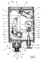
- a safety and arming device 1 consists of a housing 2 intended to be fixed to the mine and inside which is disposed a rotor 3 carrying a primer 4 .
- This rotor 3 can rotate about an axis 21 perpendicular to the plane of Figure 1 and it is immobilized in its safety position (which is that shown in Figures 1 to 3) by two locks.
- the primer 4 When the rotor is in its armed position, the primer 4 is opposite and axially aligned with an opening 67 arranged in the housing, opening which communicates with an explosive charge of the mine (not shown).
- the primer is electrically initiated, its initiation will be caused by a target detector of known type not shown, for example an infrared sensor.
- a target detector of known type not shown, for example an infrared sensor.
- a number of electrical contacts and safeties are provided in the device. They are not described or shown here since they do not form part of the present invention.
- a first lock 5 of the rotor is constituted by a first lever mounted to pivot relative to the body of the housing.
- This lever pivots around an axis 6, it has a general L shape and has a spout 7 (see FIG. 3) which engages in a notch 8 of the rotor 3.
- the spout 7 is pushed towards the rotor by the action of a compression spring 9 which bears, on the one hand on a support bar 10 secured to the device body, and on the other hand on a fold 11 of the first lever 5.
- Centering pins 12a, 12b are provided to maintain the spring during movement of the lever.
- the first lever 5 carries on a lower face (see FIG. 1) a profile 54 (in the shape of an "L") which cooperates with a stud 53 carried by a movable slide 37.
- the displacement of the slide 37 causes the pivot of the first lever 5
- the pin 53 of the slide ensuring the maintenance of the lever in its locking position of the rotor 3.
- the rotor 3 is also held in the safety position by a second lock 13 which is constituted by a second lever having a general L-shape and mounted pivoting relative to the body around the same axis 6 as the first lever 5.
- This second lever 13 includes a spout 14 (see FIG. 1) which engages in a notch 15 of the rotor 3. It is kept engaged in the notch 15 of the rotor by the action of another compression spring 16 which, he too is supported by a side on a support bar 17 secured to the device body and on the other side on a face 22 of the lever 13.
- Centering pins 18a, 18b maintain the spring 16 during the movements of the second lever.
- the first lever 5 is located below the second lever 13.
- the axis of rotation 6 and the pins for holding the bars 10 and 17 are fixed on a plate 19, itself made integral with the housing by screws 20.
- the second lever 13 can be released from the rotor 3 by manual action on a triggering member constituted by a pull tab 23.
- the pull tab has a pin 24, one enlarged end 25 of which is positioned in a housing 26 arranged at the end of a first arm 13a of the second lever 13.
- the other end of the axis 24 carries an operating button 27.
- a compression spring 28 pushes the zipper towards the second lever 13 and maintains it in the position shown in FIG. 1.
- the second lever 13 can also be released from the rotor 3 by means of an electromagnet 29, one end of the rod 30 of which is positioned in a housing 31 arranged at the end of the second arm 13b of the second lever 13.
- Figure 2 shows the safety and arming device according to the invention after removal of the plate 19 carrying the locking levers 13 and 5 and the primer carrier rotor 3, and removal of a spacer plate 52 (see Figure 4) .
- a second plate 32 appears and it is also screwed to the body of the housing.
- This second plate maintains the clock timing system 33 which is of a known type and will not be described in detail.
- This system includes a number of toothed wheels, the first wheel 34 (or drive wheel) receives the mechanical energy supplied by a compression spring 36 pushing the slide 37 which carries a rack 38.
- the last wheel 35 (or wheel of drive) is integral with the primer carrier rotor.
- a gear train brakes the rotation of the drive wheel and ensures the desired delay.
- the second plate 32 is partially removed in Figure 2 to show more clearly the control means of the device. Reference will also be made to FIG. 4 for the description of the control means.
- This control means comprises a control rod 39 which extends over substantially the entire length of the housing.
- the control rod carries at its external end a control button 40 and at its other end (internal to the housing) a movable stop 41.
- the stop 41 is made integral with the rod 39 by means of a nut 42 (see FIG. 4).
- the stop 41 has a bore 43 slidably mounted on a guide rod 44 secured to the housing.
- a compression spring 45 is mounted coaxially with the rod 44, it has the effect of pushing the stop (and the control rod 39 which is linked to it) into the position shown in FIGS. 2 and 4.
- the slide 37 is mounted free in translation on the control rod 39. It is pushed towards the stop 41 by the motor spring 36 which bears, on the one hand on a retaining washer 46 secured to the housing and on the other hand on a counterbore 47 of the internal bore 48 of the slide 37.
- the spring 36 is guided by a sleeve 49 coaxial with the control rod.
- the slider 37 has a window 50 inside which is positioned a locking cam 51 which is linked in rotation to the control rod 39 but which, driven by the slider, can translate relative to the rod 39.
- control rod has a square section and in particular carries two flats 39a, 39b which extend over its entire length (see FIG. 4a for the mounting detail of the cam 51 on the rod ).
- the function of this blocking cam will be explained below.
- the slide 37 carries on its upper face the stud 53 cited above. This circulates in longitudinal grooves 55, 56, 57 arranged respectively on the plates 32, 19 and on the spacer 52.
- the stud 53 cooperates with the surface of the profile 54 which is integral with the first locking lever 5 (see FIG. 1) so as to drive the first lever 5 and to release it or engage it in the notch 8 of the primer holder rotor.
- the housing body also carries a finger 58 pivotally mounted relative to the body about an axis 59.
- This finger can occupy at least two extreme angular positions corresponding to its abutment on an axis 60 at a cylindrical clearance 61.
- the finger 58 has a spout 62 which is intended to cooperate with a complementary spout 63 carried by the stop 41, so as to lock in translation the control rod 39 by means of the stop 41.
- the slider has an extension 65 which cooperates with a cam profile 64 integral with the finger 58, so as to cause the position of the latter to change during the translation of the slider.
- the device Once the device is closed, it forms a sealed enclosure which is isolated from the atmosphere by seals. Such an arrangement improves the resistance of the device to long-term storage.
- control rod 39 carries at its external end a valve 69 which comprises a cylinder 70 integral with the control button 40 and which can slide over a short length (1 to 2 mm) relative to an axial piston 71 integral with rod 39 (see Figure 1).
- the valve When the interior of the housing is overpressure relative to the exterior, the valve operates automatically and balances the pressures.
- a flexible bellows 72 is provided between the button 40 and the housing body 2, this in order to ensure a moisture-tightness whatever the position of the rod 39.
- the seal between the cylinder 70 and the piston 71 of the valve is ensured by one or more O-rings.
- the relative translation of the cylinder with respect to the piston makes it possible to free at least one O-ring from its contact surface, this results in a radial play of a few tenths of mm between cylinder and piston, play which is sufficient to ensure pressure balancing .
- the initiator rotor has also been drawn in FIGS. 5 to 7 in order to specify for each state of the device what is the corresponding position of the rotor.
- Figure 2 shows the device in its storage safety position.
- the initiator rotor is immobilized by two locks and the control rod is also blocked in translation due to the active position of the locking cam 51.
- the cam 51 occupies with respect to the slide 37 an angular position such that its enlarged end 51a penetrates into a rectangular opening 66 arranged on the plate 32.
- the cam 51 abuts against the plate 32 and therefore prohibits any translation of the control rod.
- the first lever 5 is immobilized in its locking position of the rotor 3 by the cooperation of the stud 53 of the slide 37 with the profile 54 of the first lever 5.
- the user begins by turning the control knob 40 by 90 °. This action has the effect of rotating the locking cam 51 which is then completely housed in the slide 37 and no longer interferes with the plate 32. Traction of the control rod then becomes possible.
- Figure 5 shows schematically the device when the control rod 39 is fully pulled.
- the locking finger 58 has been tilted (in the direction F) from its initial position to its second position by the passage of the extension 65 of the slide 37 on the cam profile 64 of the finger 58.
- the displacement of the slide 37 also causes the release of the first lock of the initiator rotor by the action of the stud 53.
- the profile 54 is defined so that this release only occurs when the slide 37 arrives a few millimeters from its position extreme.
- the second lock 13 is still engaged in the rotor which therefore remains in the safety position.
- Figure 6 shows the device after the control rod has been released.
- the stop 41 pushed by the return spring 45, returns to its initial position and drives the control rod 39.
- the stop pushes the locking finger 58 in the direction G in passing, the latter not yet being blocked by the slide 37.
- the mainspring 36 exerts a thrust on the slider 37, but the second lock 13 still being engaged in the rotor, the slider remains blocked by the time delay 33 in the position shown in FIG. 6.
- the action on the zipper can be replaced by an action of the electromagnet 29, controlled remotely, for example by a radio remote control.
- the timer cannot be released that if the two locks of the rotor are released, or the first lock has a position of the profile 54 (fig 1) such that it is only released by the stud 53 of the slide only when the latter is 1 or 2 millimeters from the position shown in Figure 5 (ie that corresponding to the maximum traction for the rod).
- the movement of the slide causes the locking finger 58 to tilt in the direction F from the start of the time delay, due to the action of the extension 65 on the cam profile 64.
- the finger adopts the locking position shown in FIG. 7, in which its spout 62 prevents any axial movement of the stop 41 (and therefore of the control pin 39).
- the slide 37 blocks the locking finger 58 in this position, and this throughout the delay time as well as when the device is in the armed position shown in FIG. 7. It is therefore no longer possible to exert traction on the control rod 39, which eliminates the risk of seeing a new traction cause a shift in the time delay which could lead to a modification of the delay times, or even to an immediate passage into the armed position.
- the timing gear train comprises at least two superposed coaxial wheels, one driven by the rack 38 of the slide and the other driving the primer rotor.
- the wheel driven by the rack is braked by the timing gear train. It comprises a sector devoid of teeth (not shown) which makes it possible to disengage the time delay when the slide is in a position close to the position shown in FIG. 7.
- This arrangement ensures rapid passage of the rotor to its armed position at the end of the time delay.
- the correct position of the rotor is ensured by the presence of the second locking lever 13, the spout 14 of which acts as a stop for the rotor which, for this purpose, carries a stop tooth 68 on its periphery.
- the armed position of the rotor is shown in Figure 7.
- the primer 4 is aligned with the opening 67 of the housing and with the explosive charge of the mine.
- the mine awaits the passage of a target which will cause the initiation of the primer by means of a detection device of known type and not described here.
- the motor spring 36 pushes the slide 37 and causes the rotor 3 to pass instantaneously into the safety position (position in FIG. 2).
- the shift is instantaneous due to the disengagement described above of the gear train, disengagement which occurred at the end of the delay period.
- the slider 37 resumes at the same time its position of FIG. 2 in which it has tilted the locking finger in the release position of the stop 41.
- the displacement of the slider has also caused the return of the first lock 5 of the rotor by the cooperation of the stud 53 with the profile 54. This lock again ensures that the rotor is blocked when the latter has returned to its safety position.
- the second rotor lock pushed by its spring 16 resumes also its blocking position.
- the device therefore regains all of its initial security functions and can be used again with the same level of security and reliability.
- the device according to the invention thus allows an indefinite number of successive re-uses of the mine while each time retaining the same level of security and reliability.
- Neutralization of the mine can also be triggered remotely or it can intervene automatically at the end of a lifetime programmed in the mine electronics.
- the electromagnet 29 will be controlled and will release the second lock 13.
Landscapes
- Engineering & Computer Science (AREA)
- General Engineering & Computer Science (AREA)
- Mechanical Control Devices (AREA)
- Toys (AREA)
- Lock And Its Accessories (AREA)
- Ignition Installations For Internal Combustion Engines (AREA)
Applications Claiming Priority (2)
| Application Number | Priority Date | Filing Date | Title |
|---|---|---|---|
| FR9606285 | 1996-05-21 | ||
| FR9606285A FR2749072B1 (fr) | 1996-05-21 | 1996-05-21 | Dispositif de securite et d'armement notamment pour mine |
Publications (2)
| Publication Number | Publication Date |
|---|---|
| EP0809085A1 true EP0809085A1 (de) | 1997-11-26 |
| EP0809085B1 EP0809085B1 (de) | 2001-08-22 |
Family
ID=9492312
Family Applications (1)
| Application Number | Title | Priority Date | Filing Date |
|---|---|---|---|
| EP19970400962 Expired - Lifetime EP0809085B1 (de) | 1996-05-21 | 1997-04-29 | Sicherheits- und Spannvorrichtung, insbesondere für Minen |
Country Status (4)
| Country | Link |
|---|---|
| EP (1) | EP0809085B1 (de) |
| DE (1) | DE69706231T2 (de) |
| FR (1) | FR2749072B1 (de) |
| NO (1) | NO972293L (de) |
Cited By (1)
| Publication number | Priority date | Publication date | Assignee | Title |
|---|---|---|---|---|
| WO2017109313A1 (fr) * | 2015-12-22 | 2017-06-29 | Nexter Munitions | Dispositif de securite et d'armement reversible pour un engin explosif |
Citations (3)
| Publication number | Priority date | Publication date | Assignee | Title |
|---|---|---|---|---|
| DE2802700A1 (de) * | 1978-01-23 | 1979-07-26 | Hagenuk Neufeldt Kuhnke Gmbh | Sicherheitsarmatur fuer seeminen |
| BE877259A (fr) * | 1978-08-03 | 1979-10-15 | Valsella Spa | Systeme d'allumage de mines explosives et dispositif de controle de l'etat de fonctionnement de la mine |
| DE2952722C1 (de) * | 1979-12-29 | 1984-09-06 | Hagenuk GmbH, 2300 Kiel | Sicherheitsarmatur fuer Seeminen |
-
1996
- 1996-05-21 FR FR9606285A patent/FR2749072B1/fr not_active Expired - Fee Related
-
1997
- 1997-04-29 EP EP19970400962 patent/EP0809085B1/de not_active Expired - Lifetime
- 1997-04-29 DE DE1997606231 patent/DE69706231T2/de not_active Expired - Fee Related
- 1997-05-20 NO NO972293A patent/NO972293L/no unknown
Patent Citations (3)
| Publication number | Priority date | Publication date | Assignee | Title |
|---|---|---|---|---|
| DE2802700A1 (de) * | 1978-01-23 | 1979-07-26 | Hagenuk Neufeldt Kuhnke Gmbh | Sicherheitsarmatur fuer seeminen |
| BE877259A (fr) * | 1978-08-03 | 1979-10-15 | Valsella Spa | Systeme d'allumage de mines explosives et dispositif de controle de l'etat de fonctionnement de la mine |
| DE2952722C1 (de) * | 1979-12-29 | 1984-09-06 | Hagenuk GmbH, 2300 Kiel | Sicherheitsarmatur fuer Seeminen |
Cited By (1)
| Publication number | Priority date | Publication date | Assignee | Title |
|---|---|---|---|---|
| WO2017109313A1 (fr) * | 2015-12-22 | 2017-06-29 | Nexter Munitions | Dispositif de securite et d'armement reversible pour un engin explosif |
Also Published As
| Publication number | Publication date |
|---|---|
| NO972293D0 (no) | 1997-05-20 |
| DE69706231D1 (de) | 2001-09-27 |
| NO972293L (no) | 1997-11-24 |
| FR2749072B1 (fr) | 1998-07-10 |
| DE69706231T2 (de) | 2002-04-18 |
| EP0809085B1 (de) | 2001-08-22 |
| FR2749072A1 (fr) | 1997-11-28 |
Similar Documents
| Publication | Publication Date | Title |
|---|---|---|
| FR2500617A1 (fr) | Dispositif de surete pour fusee de projectiles stabilises par rotation | |
| CH615830A5 (de) | ||
| EP1544098A1 (de) | Antriebsvorrichtung zum Versetzen eines Verschlusselements für Fahrzeuge | |
| EP0391782B1 (de) | Detektionseinrichtung für die Überschreitung eines Temperaturwertes | |
| EP0809085B1 (de) | Sicherheits- und Spannvorrichtung, insbesondere für Minen | |
| FR2616350A1 (fr) | Arme-jouet pour le tir pneumatique de projectiles avec piston combine au chien | |
| FR2504254A1 (fr) | Mine antichar perfectionnee | |
| WO1991018168A1 (fr) | Dispositif de commande du declenchement temporise d'un mecanisme | |
| EP0075496B1 (de) | Vorkehrungen zum Sichern und Schärfen an Unterwasserzündern | |
| FR2691797A1 (fr) | Système de sécurité et d'armement pour sous-munition, en particulier pour sous-munition embarquée dans un obus cargo. | |
| EP2104009B1 (de) | Chronograph diving watch | |
| CH708902A2 (fr) | Pièce d'horlogerie à animation. | |
| EP0627067B1 (de) | Zünd- und selbstzerlegungssystem für submunition | |
| FR2563622A1 (fr) | Dispositif de securite et d'armement pour engins explosifs | |
| EP4176225B1 (de) | Zünder mit selbstzerstörungsvorrichtung für ein kreiselgeschoss | |
| CH719641B1 (fr) | Dispositif d'actionnement pour mouvement horloger, mouvement horloger et pièce d'horlogerie correspondants. | |
| FR2699662A1 (fr) | Système d'amorçage à détecteur d'impact tout azimut pour munition, en particulier pour sous-munition éjectée d'un obus cargo. | |
| FR2531204A1 (fr) | Fusee de culot a armement automatique pour grenade a fusil | |
| FR2691798A1 (fr) | Système d'auto-destruction d'une munition, en particulier d'une sous-munition d'obus cargo par attaque chimique. | |
| EP0269931A1 (de) | Schloss mit Zeitschaltung | |
| FR2499710A1 (fr) | Dispositif retardateur chronometrique indetectable | |
| EP0098231A1 (de) | Gashahn mit piezoelektrischer Vorrichtung und gasbeheizte Geräte mit einem solchen Gashahn | |
| FR2606136A1 (fr) | Dispositif de securite et d'armement pour sous-projectiles dispersables | |
| FR2699661A1 (fr) | Système d'amorçage d'une munition par percussion radiale, en particulier d'une sous-munition destinée à être éjectée d'un obus cargo. | |
| CH717245A2 (fr) | Pièce d'horlogerie comprenant un dispositif de commande étanche. |
Legal Events
| Date | Code | Title | Description |
|---|---|---|---|
| PUAI | Public reference made under article 153(3) epc to a published international application that has entered the european phase |
Free format text: ORIGINAL CODE: 0009012 |
|
| AK | Designated contracting states |
Kind code of ref document: A1 Designated state(s): DE GB SE |
|
| 17P | Request for examination filed |
Effective date: 19980509 |
|
| 17Q | First examination report despatched |
Effective date: 19991117 |
|
| GRAG | Despatch of communication of intention to grant |
Free format text: ORIGINAL CODE: EPIDOS AGRA |
|
| GRAG | Despatch of communication of intention to grant |
Free format text: ORIGINAL CODE: EPIDOS AGRA |
|
| GRAH | Despatch of communication of intention to grant a patent |
Free format text: ORIGINAL CODE: EPIDOS IGRA |
|
| GRAH | Despatch of communication of intention to grant a patent |
Free format text: ORIGINAL CODE: EPIDOS IGRA |
|
| GRAA | (expected) grant |
Free format text: ORIGINAL CODE: 0009210 |
|
| AK | Designated contracting states |
Kind code of ref document: B1 Designated state(s): DE GB SE |
|
| GBT | Gb: translation of ep patent filed (gb section 77(6)(a)/1977) |
Effective date: 20010822 |
|
| REF | Corresponds to: |
Ref document number: 69706231 Country of ref document: DE Date of ref document: 20010927 |
|
| PG25 | Lapsed in a contracting state [announced via postgrant information from national office to epo] |
Ref country code: SE Free format text: LAPSE BECAUSE OF FAILURE TO SUBMIT A TRANSLATION OF THE DESCRIPTION OR TO PAY THE FEE WITHIN THE PRESCRIBED TIME-LIMIT Effective date: 20011122 |
|
| REG | Reference to a national code |
Ref country code: GB Ref legal event code: IF02 |
|
| PGFP | Annual fee paid to national office [announced via postgrant information from national office to epo] |
Ref country code: GB Payment date: 20020327 Year of fee payment: 6 |
|
| PGFP | Annual fee paid to national office [announced via postgrant information from national office to epo] |
Ref country code: DE Payment date: 20020412 Year of fee payment: 6 |
|
| PLBE | No opposition filed within time limit |
Free format text: ORIGINAL CODE: 0009261 |
|
| 26N | No opposition filed | ||
| PG25 | Lapsed in a contracting state [announced via postgrant information from national office to epo] |
Ref country code: GB Free format text: LAPSE BECAUSE OF NON-PAYMENT OF DUE FEES Effective date: 20030429 |
|
| PG25 | Lapsed in a contracting state [announced via postgrant information from national office to epo] |
Ref country code: DE Free format text: LAPSE BECAUSE OF NON-PAYMENT OF DUE FEES Effective date: 20031101 |
|
| GBPC | Gb: european patent ceased through non-payment of renewal fee |