EP0809166A2 - Servomécanisme à entraînement à vis - Google Patents
Servomécanisme à entraînement à vis Download PDFInfo
- Publication number
- EP0809166A2 EP0809166A2 EP97710010A EP97710010A EP0809166A2 EP 0809166 A2 EP0809166 A2 EP 0809166A2 EP 97710010 A EP97710010 A EP 97710010A EP 97710010 A EP97710010 A EP 97710010A EP 0809166 A2 EP0809166 A2 EP 0809166A2
- Authority
- EP
- European Patent Office
- Prior art keywords
- threaded
- actuator
- servomotor
- actuator according
- leveling
- Prior art date
- Legal status (The legal status is an assumption and is not a legal conclusion. Google has not performed a legal analysis and makes no representation as to the accuracy of the status listed.)
- Granted
Links
Images


Classifications
-
- E—FIXED CONSTRUCTIONS
- E04—BUILDING
- E04F—FINISHING WORK ON BUILDINGS, e.g. STAIRS, FLOORS
- E04F21/00—Implements for finishing work on buildings
- E04F21/20—Implements for finishing work on buildings for laying flooring
-
- G—PHYSICS
- G01—MEASURING; TESTING
- G01C—MEASURING DISTANCES, LEVELS OR BEARINGS; SURVEYING; NAVIGATION; GYROSCOPIC INSTRUMENTS; PHOTOGRAMMETRY OR VIDEOGRAMMETRY
- G01C15/00—Surveying instruments or accessories not provided for in groups G01C1/00 - G01C13/00
- G01C15/002—Active optical surveying means
- G01C15/004—Reference lines, planes or sectors
-
- G—PHYSICS
- G01—MEASURING; TESTING
- G01C—MEASURING DISTANCES, LEVELS OR BEARINGS; SURVEYING; NAVIGATION; GYROSCOPIC INSTRUMENTS; PHOTOGRAMMETRY OR VIDEOGRAMMETRY
- G01C5/00—Measuring height; Measuring distances transverse to line of sight; Levelling between separated points; Surveyors' levels
- G01C5/04—Hydrostatic levelling, i.e. by flexibly interconnected liquid containers at separated points
-
- G—PHYSICS
- G01—MEASURING; TESTING
- G01D—MEASURING NOT SPECIALLY ADAPTED FOR A SPECIFIC VARIABLE; ARRANGEMENTS FOR MEASURING TWO OR MORE VARIABLES NOT COVERED IN A SINGLE OTHER SUBCLASS; TARIFF METERING APPARATUS; MEASURING OR TESTING NOT OTHERWISE PROVIDED FOR
- G01D7/00—Indicating measured values
- G01D7/12—Audible indication of meter readings, e.g. for the blind
Definitions
- the present invention relates to a threaded actuator with an actuator guided in a threaded bearing, for example in the form of a screed leveling bracket, concrete leveling bracket or a threaded actuator for cavity floor feet or ceiling constructions.
- Such actuators verden z. B. used to level height levels of liquid screed, concrete structures, false floor feet or corresponding ceiling structures.
- the leveling was carried out in a conventional manner by manual adjustment of the threaded actuator, for example the spindle leveling blocks, using a conventional leveling device.
- the threaded spindle was adjusted to the desired level by turning it by hand, which is time-consuming and uncomfortable since the operator has to bend down for each adjustment process in order to access the threaded spindle. It is also possible that reading errors occur when reading the conventional leveling device and the desired level is thereby incorrectly set. Nevertheless, this conventional method of level adjustment has been kept unchanged for more than 20 years because the person skilled in the art apparently did not consider a simpler and more convenient method to be feasible.
- the object of the present invention is to provide a threaded actuator which avoids the disadvantages of the conventional actuators and can be adjusted quickly and with high accuracy to a desired level simply and without bending over of the operating personnel, that is to say with an ergonomic working posture. It should be possible to level the threaded actuator with all conventional leveling devices.
- the invention enables rapid automatic or manual setting of the desired level, considerably simplified handling and very precise setting. Constant bending and straightening of the operating personnel is avoided, which means that, for example, significantly more spindle leveling stands can be leveled in a much shorter time.
- the threaded actuator contains an actuator guided in a threaded bearing, on which a servomotor is arranged which, by means of its rotary movement, adjusts the actuator in its threaded bearing.
- the servomotor is actuated by an up-down switching device, whereby the actuator is guided upwards or downwards in the threaded bearing.
- the up-down switching device is coupled to an electronic measured value recording device, for example to an electronic hose leveling device, as is known, for. B. is described in DE-GM 296 01 987.9. Also coupling with a laser leveling device is possible.
- the height measurement values recorded electronically with the devices can be converted, for example in a processor, into control pulses for the servomotor.
- the measured height values can also be displayed optically or acoustically and converted manually into control pulses for the servomotor, for example via an up-down switch.
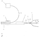
- a liquid screed spindle leveling block 7 is shown as a threaded actuator, which contains three angled feet 16 which are arranged on a threaded bearing 14.
- a threaded rod 12 runs in the threaded bearing 14 and is connected to the servomotor 6 via a drive connection 18.
- the threaded rod 14 moves up or down depending on the direction of rotation of the servomotor 6.
- a leveling disk 20 which serves as a reference point for the level to be leveled.
- the servomotor 6 is controlled by an electronic measured value detection device 1, as described, for example, in DE-GM 296 10 987.9. It contains a water-filled absolute zero sensor 8, e.g. in the form of a vessel open to the outside atmosphere, which is connected via a water-filled hose 22 to a differential pressure sensor arranged in the measured value detection device 1, which detects the differences in the measured height values and the electronic measured values thus determined via a processor in control pulses for the servomotor 6 converts. When the electronic measured value recording device 1 is activated by the button 4, the servomotor 6 thus sets the leveling disk 20 to the desired level.
- FIG. 2 shows a combination of a liquid screed spindle leveling block 7 with a laser measured value detection device 2.
- the lower part with the liquid screed spindle leveling block 7 and the servomotor 6 corresponds to the arrangement in FIG. 1.
- the laser measured value detection device 2 receives the Laser beam 13 emitted by the leveling laser 9 and displays the measured height measurement values on an optical display or converts them into control pulses for the servomotor 6 via a processor. With a visual display, the servomotor 6 is moved to the desired level using the button 11.
- FIG. 3 Another possible application is shown in FIG. 3.
- a manual measured value acquisition device for example in the form of an optical measured value acquisition device 3, which can be designed as a tube scale. It contains an absolute zero sensor 9 in the form of an open or closed vessel, which is connected via a hose 22, which is filled with a liquid, for example water, to the manual measured value recording device 3, which can consist of a riser provided with graduations.
- the servomotor 6 can be controlled with the two buttons.
- the servomotor 6 can be detachably connected to the actuator 10, for example via a pluggable drive connection 18 containing a socket into which a plug-in mandrel connected to the drive shaft of the servomotor 6 is inserted. In this way, all of the above-mentioned measured value recording devices can be combined with the servomotor and thus with the threaded actuator.
Landscapes
- Engineering & Computer Science (AREA)
- Physics & Mathematics (AREA)
- General Physics & Mathematics (AREA)
- Architecture (AREA)
- Radar, Positioning & Navigation (AREA)
- Remote Sensing (AREA)
- Civil Engineering (AREA)
- Structural Engineering (AREA)
- Control Of Position Or Direction (AREA)
- Length Measuring Devices By Optical Means (AREA)
Applications Claiming Priority (4)
| Application Number | Priority Date | Filing Date | Title |
|---|---|---|---|
| DE29601987U DE29601987U1 (de) | 1996-02-06 | 1996-02-06 | Elektronisches Schlauchnivelliermeßgerät |
| DE29601987U | 1996-05-21 | ||
| DE29609271U DE29609271U1 (de) | 1996-05-23 | 1996-05-23 | Motorgesteuertes Höhenmaßeinstellgerät für Fließestrichspindelnivellierböcke |
| DE29609271U | 1996-05-23 |
Publications (3)
| Publication Number | Publication Date |
|---|---|
| EP0809166A2 true EP0809166A2 (fr) | 1997-11-26 |
| EP0809166A3 EP0809166A3 (fr) | 1998-05-13 |
| EP0809166B1 EP0809166B1 (fr) | 2001-09-12 |
Family
ID=26058619
Family Applications (1)
| Application Number | Title | Priority Date | Filing Date |
|---|---|---|---|
| EP19970710010 Expired - Lifetime EP0809166B1 (fr) | 1996-02-06 | 1997-05-21 | Servomécanisme à entraínement à vis |
Country Status (1)
| Country | Link |
|---|---|
| EP (1) | EP0809166B1 (fr) |
Cited By (1)
| Publication number | Priority date | Publication date | Assignee | Title |
|---|---|---|---|---|
| WO2010112919A1 (fr) * | 2009-03-30 | 2010-10-07 | Deer Park Engineering Limited | Dispositif et procede de construction pour bâtiment |
Family Cites Families (6)
| Publication number | Priority date | Publication date | Assignee | Title |
|---|---|---|---|---|
| DE3143713A1 (de) * | 1981-11-04 | 1983-05-11 | Wolfgang 6380 Bad Homburg Nesselberger | "einrichtung zum abstuetzen und nivellieren eines wohnwagens oder dergleichen" |
| DE3713006A1 (de) * | 1987-04-16 | 1988-10-27 | Hydro Geraetebau Gmbh & Co Kg | Einrichtung zum hochbocken von fahrzeugen |
| US4993161A (en) * | 1990-01-04 | 1991-02-19 | David White, Inc. | Laser beam level instrument |
| DE4310003C1 (de) * | 1993-03-27 | 1994-06-01 | Medical Objekteinrichtung Gmbh | Bett, insbesondere Kranken- und/oder Pflegebett |
| DE29601987U1 (de) * | 1996-02-06 | 1996-03-28 | Straub, Wolfgang, 63877 Sailauf | Elektronisches Schlauchnivelliermeßgerät |
| DE19626770C1 (de) * | 1996-07-03 | 1998-03-26 | Martin Theodor Melchior | Nivellierbock |
-
1997
- 1997-05-21 EP EP19970710010 patent/EP0809166B1/fr not_active Expired - Lifetime
Cited By (1)
| Publication number | Priority date | Publication date | Assignee | Title |
|---|---|---|---|---|
| WO2010112919A1 (fr) * | 2009-03-30 | 2010-10-07 | Deer Park Engineering Limited | Dispositif et procede de construction pour bâtiment |
Also Published As
| Publication number | Publication date |
|---|---|
| EP0809166A3 (fr) | 1998-05-13 |
| EP0809166B1 (fr) | 2001-09-12 |
Similar Documents
| Publication | Publication Date | Title |
|---|---|---|
| DE3827458C3 (de) | Verfahren und Vorrichtung zur Ermittlung der Raumkoordinaten eines beliebigen Meßpunktes | |
| DE4002493C2 (fr) | ||
| CH688161A5 (de) | Ausbalancierbares Stativ. | |
| CH691873A5 (de) | Verfahren und Einrichtung zum Beschichten von Tunnelinnenwänden mit Spritzbeton. | |
| EP0481278A1 (fr) | Procédé et installation de mesure pour localisation de points dans l'espace | |
| WO2000026615A1 (fr) | Dispositif pour determiner les coordonnees spatiales d'objets | |
| DE69927597T2 (de) | Verfahren und Vorrichtung zur Falzwinkelmessung eines Blattes in einer Falzmaschine | |
| DE4213312A1 (de) | Operationsmikroskop | |
| DE3121070C2 (fr) | ||
| DE2821112A1 (de) | Verfahren und vorrichtung zur maschinellen einstellung der neigung einer gesteinsbohrvorrichtung | |
| EP1324094A2 (fr) | Support pour un appareil optique de visualisation | |
| DE3833203C1 (en) | Device for the numeric acquisition of coordinates for CAD systems | |
| EP0809166A2 (fr) | Servomécanisme à entraînement à vis | |
| DE2818028A1 (de) | Verfahren und vorrichtung zur steuerung der position des saugrohres eines schwimmbaggers | |
| EP3614100B1 (fr) | Dispositif de nivellement de masses de coulée telle qu'une chape ou béton pompé ainsi que dispositif de mesure doté d'un tel dispositif | |
| DE102005018326B4 (de) | Steuerungsverfahren zur Bewegungsführung eines hinsichtlich seiner Halteposition bewegbaren, dabei zu einer Schwingung anregbaren Röntgenstrahlers und/oder Röntgenempfängers eines Röntgenuntersuchungssystems | |
| DE102020006290A1 (de) | Adapter für ein Trägerelement eines Vermessungsinstruments und Verfahren | |
| DE4203284C2 (de) | Verfahren und Vorrichtung zum Programmieren numerisch gesteuerter Werkzeugmaschinen | |
| CH680621A5 (en) | Measuring system for shaft or drainage channel condition - uses computer-controlled measuring head to scan inside surface of shaft or channel with monitor display | |
| DE9007731U1 (de) | Meßeinrichtung zur Positionsbestimmung opto-elektronisch darstellbarer Raumpunkte | |
| EP3382338A1 (fr) | Capteur de position | |
| WO1996017222A1 (fr) | Procede et dispositif de mesurage optique de surfaces de montage | |
| AT527252B1 (de) | Messstab zur Verwendung in einem Lasernivellierungssystem | |
| DE69417703T2 (de) | Hydrostatische Schlauchwaage | |
| DE3413796C2 (fr) |
Legal Events
| Date | Code | Title | Description |
|---|---|---|---|
| PUAI | Public reference made under article 153(3) epc to a published international application that has entered the european phase |
Free format text: ORIGINAL CODE: 0009012 |
|
| AK | Designated contracting states |
Kind code of ref document: A2 Designated state(s): AT BE CH DE DK ES FI FR GB GR IE IT LI LU MC NL PT SE |
|
| PUAL | Search report despatched |
Free format text: ORIGINAL CODE: 0009013 |
|
| AK | Designated contracting states |
Kind code of ref document: A3 Designated state(s): AT BE CH DE DK ES FI FR GB GR IE IT LI LU MC NL PT SE |
|
| 17P | Request for examination filed |
Effective date: 19980921 |
|
| 17Q | First examination report despatched |
Effective date: 20000331 |
|
| GRAG | Despatch of communication of intention to grant |
Free format text: ORIGINAL CODE: EPIDOS AGRA |
|
| GRAG | Despatch of communication of intention to grant |
Free format text: ORIGINAL CODE: EPIDOS AGRA |
|
| GRAH | Despatch of communication of intention to grant a patent |
Free format text: ORIGINAL CODE: EPIDOS IGRA |
|
| GRAH | Despatch of communication of intention to grant a patent |
Free format text: ORIGINAL CODE: EPIDOS IGRA |
|
| GRAA | (expected) grant |
Free format text: ORIGINAL CODE: 0009210 |
|
| AK | Designated contracting states |
Kind code of ref document: B1 Designated state(s): AT BE CH DE DK ES FI FR GB GR IE IT LI LU MC NL PT SE |
|
| PG25 | Lapsed in a contracting state [announced via postgrant information from national office to epo] |
Ref country code: NL Free format text: LAPSE BECAUSE OF FAILURE TO SUBMIT A TRANSLATION OF THE DESCRIPTION OR TO PAY THE FEE WITHIN THE PRESCRIBED TIME-LIMIT Effective date: 20010912 Ref country code: IT Free format text: LAPSE BECAUSE OF FAILURE TO SUBMIT A TRANSLATION OF THE DESCRIPTION OR TO PAY THE FEE WITHIN THE PRESCRIBED TIME-LIMIT;WARNING: LAPSES OF ITALIAN PATENTS WITH EFFECTIVE DATE BEFORE 2007 MAY HAVE OCCURRED AT ANY TIME BEFORE 2007. THE CORRECT EFFECTIVE DATE MAY BE DIFFERENT FROM THE ONE RECORDED. Effective date: 20010912 Ref country code: IE Free format text: LAPSE BECAUSE OF FAILURE TO SUBMIT A TRANSLATION OF THE DESCRIPTION OR TO PAY THE FEE WITHIN THE PRESCRIBED TIME-LIMIT Effective date: 20010912 Ref country code: GB Free format text: LAPSE BECAUSE OF FAILURE TO SUBMIT A TRANSLATION OF THE DESCRIPTION OR TO PAY THE FEE WITHIN THE PRESCRIBED TIME-LIMIT Effective date: 20010912 Ref country code: FR Free format text: LAPSE BECAUSE OF FAILURE TO SUBMIT A TRANSLATION OF THE DESCRIPTION OR TO PAY THE FEE WITHIN THE PRESCRIBED TIME-LIMIT Effective date: 20010912 Ref country code: FI Free format text: LAPSE BECAUSE OF FAILURE TO SUBMIT A TRANSLATION OF THE DESCRIPTION OR TO PAY THE FEE WITHIN THE PRESCRIBED TIME-LIMIT Effective date: 20010912 |
|
| REF | Corresponds to: |
Ref document number: 205610 Country of ref document: AT Date of ref document: 20010915 Kind code of ref document: T |
|
| REG | Reference to a national code |
Ref country code: CH Ref legal event code: EP |
|
| REG | Reference to a national code |
Ref country code: IE Ref legal event code: FG4D Free format text: GERMAN |
|
| REF | Corresponds to: |
Ref document number: 59704574 Country of ref document: DE Date of ref document: 20011018 |
|
| PG25 | Lapsed in a contracting state [announced via postgrant information from national office to epo] |
Ref country code: SE Free format text: LAPSE BECAUSE OF FAILURE TO SUBMIT A TRANSLATION OF THE DESCRIPTION OR TO PAY THE FEE WITHIN THE PRESCRIBED TIME-LIMIT Effective date: 20011212 Ref country code: PT Free format text: LAPSE BECAUSE OF FAILURE TO SUBMIT A TRANSLATION OF THE DESCRIPTION OR TO PAY THE FEE WITHIN THE PRESCRIBED TIME-LIMIT Effective date: 20011212 Ref country code: DK Free format text: LAPSE BECAUSE OF FAILURE TO SUBMIT A TRANSLATION OF THE DESCRIPTION OR TO PAY THE FEE WITHIN THE PRESCRIBED TIME-LIMIT Effective date: 20011212 |
|
| PG25 | Lapsed in a contracting state [announced via postgrant information from national office to epo] |
Ref country code: GR Free format text: LAPSE BECAUSE OF FAILURE TO SUBMIT A TRANSLATION OF THE DESCRIPTION OR TO PAY THE FEE WITHIN THE PRESCRIBED TIME-LIMIT Effective date: 20011214 |
|
| NLV1 | Nl: lapsed or annulled due to failure to fulfill the requirements of art. 29p and 29m of the patents act | ||
| GBV | Gb: ep patent (uk) treated as always having been void in accordance with gb section 77(7)/1977 [no translation filed] |
Effective date: 20010912 |
|
| PG25 | Lapsed in a contracting state [announced via postgrant information from national office to epo] |
Ref country code: ES Free format text: LAPSE BECAUSE OF FAILURE TO SUBMIT A TRANSLATION OF THE DESCRIPTION OR TO PAY THE FEE WITHIN THE PRESCRIBED TIME-LIMIT Effective date: 20020326 |
|
| PG25 | Lapsed in a contracting state [announced via postgrant information from national office to epo] |
Ref country code: MC Free format text: LAPSE BECAUSE OF NON-PAYMENT OF DUE FEES Effective date: 20020521 Ref country code: LU Free format text: LAPSE BECAUSE OF NON-PAYMENT OF DUE FEES Effective date: 20020521 Ref country code: AT Free format text: LAPSE BECAUSE OF NON-PAYMENT OF DUE FEES Effective date: 20020521 |
|
| REG | Reference to a national code |
Ref country code: IE Ref legal event code: FD4D |
|
| PG25 | Lapsed in a contracting state [announced via postgrant information from national office to epo] |
Ref country code: LI Free format text: LAPSE BECAUSE OF NON-PAYMENT OF DUE FEES Effective date: 20020531 Ref country code: CH Free format text: LAPSE BECAUSE OF NON-PAYMENT OF DUE FEES Effective date: 20020531 Ref country code: BE Free format text: LAPSE BECAUSE OF NON-PAYMENT OF DUE FEES Effective date: 20020531 |
|
| PLBE | No opposition filed within time limit |
Free format text: ORIGINAL CODE: 0009261 |
|
| STAA | Information on the status of an ep patent application or granted ep patent |
Free format text: STATUS: NO OPPOSITION FILED WITHIN TIME LIMIT |
|
| EN | Fr: translation not filed | ||
| 26N | No opposition filed | ||
| REG | Reference to a national code |
Ref country code: CH Ref legal event code: PL |
|
| PGFP | Annual fee paid to national office [announced via postgrant information from national office to epo] |
Ref country code: DE Payment date: 20070725 Year of fee payment: 11 |
|
| PG25 | Lapsed in a contracting state [announced via postgrant information from national office to epo] |
Ref country code: DE Free format text: LAPSE BECAUSE OF NON-PAYMENT OF DUE FEES Effective date: 20081202 |