EP0809276B1 - Quecksilberdampfgefüllte Niederdruckentladungslampe - Google Patents
Quecksilberdampfgefüllte Niederdruckentladungslampe Download PDFInfo
- Publication number
- EP0809276B1 EP0809276B1 EP96108251A EP96108251A EP0809276B1 EP 0809276 B1 EP0809276 B1 EP 0809276B1 EP 96108251 A EP96108251 A EP 96108251A EP 96108251 A EP96108251 A EP 96108251A EP 0809276 B1 EP0809276 B1 EP 0809276B1
- Authority
- EP
- European Patent Office
- Prior art keywords
- amalgam
- container
- opening
- low pressure
- discharge space
- Prior art date
- Legal status (The legal status is an assumption and is not a legal conclusion. Google has not performed a legal analysis and makes no representation as to the accuracy of the status listed.)
- Expired - Lifetime
Links
- QSHDDOUJBYECFT-UHFFFAOYSA-N mercury Chemical compound [Hg] QSHDDOUJBYECFT-UHFFFAOYSA-N 0.000 title claims description 150
- 229910052753 mercury Inorganic materials 0.000 title claims description 49
- 229910000497 Amalgam Inorganic materials 0.000 claims description 203
- 230000004888 barrier function Effects 0.000 claims description 34
- 239000002245 particle Substances 0.000 claims description 26
- 239000000463 material Substances 0.000 claims description 20
- 239000011521 glass Substances 0.000 claims description 14
- 230000002776 aggregation Effects 0.000 claims description 12
- 238000004220 aggregation Methods 0.000 claims description 12
- 239000005373 porous glass Substances 0.000 claims description 8
- APFVFJFRJDLVQX-UHFFFAOYSA-N indium atom Chemical compound [In] APFVFJFRJDLVQX-UHFFFAOYSA-N 0.000 claims description 7
- GWEVSGVZZGPLCZ-UHFFFAOYSA-N Titan oxide Chemical compound O=[Ti]=O GWEVSGVZZGPLCZ-UHFFFAOYSA-N 0.000 claims description 6
- 229910021536 Zeolite Inorganic materials 0.000 claims description 6
- HNPSIPDUKPIQMN-UHFFFAOYSA-N dioxosilane;oxo(oxoalumanyloxy)alumane Chemical compound O=[Si]=O.O=[Al]O[Al]=O HNPSIPDUKPIQMN-UHFFFAOYSA-N 0.000 claims description 6
- 239000010457 zeolite Substances 0.000 claims description 6
- 239000000454 talc Substances 0.000 claims description 5
- 229910052623 talc Inorganic materials 0.000 claims description 5
- VYPSYNLAJGMNEJ-UHFFFAOYSA-N Silicium dioxide Chemical compound O=[Si]=O VYPSYNLAJGMNEJ-UHFFFAOYSA-N 0.000 claims description 4
- 229910052738 indium Inorganic materials 0.000 claims description 4
- 239000000395 magnesium oxide Substances 0.000 claims description 4
- CPLXHLVBOLITMK-UHFFFAOYSA-N magnesium oxide Inorganic materials [Mg]=O CPLXHLVBOLITMK-UHFFFAOYSA-N 0.000 claims description 4
- AXZKOIWUVFPNLO-UHFFFAOYSA-N magnesium;oxygen(2-) Chemical compound [O-2].[Mg+2] AXZKOIWUVFPNLO-UHFFFAOYSA-N 0.000 claims description 4
- 229910001404 rare earth metal oxide Inorganic materials 0.000 claims description 4
- 229910052814 silicon oxide Inorganic materials 0.000 claims description 4
- 239000011135 tin Substances 0.000 claims description 4
- 229910052718 tin Inorganic materials 0.000 claims description 4
- OGIDPMRJRNCKJF-UHFFFAOYSA-N titanium oxide Inorganic materials [Ti]=O OGIDPMRJRNCKJF-UHFFFAOYSA-N 0.000 claims description 4
- ATJFFYVFTNAWJD-UHFFFAOYSA-N Tin Chemical compound [Sn] ATJFFYVFTNAWJD-UHFFFAOYSA-N 0.000 claims description 3
- HCHKCACWOHOZIP-UHFFFAOYSA-N Zinc Chemical compound [Zn] HCHKCACWOHOZIP-UHFFFAOYSA-N 0.000 claims description 3
- 229910052797 bismuth Inorganic materials 0.000 claims description 3
- JCXGWMGPZLAOME-UHFFFAOYSA-N bismuth atom Chemical compound [Bi] JCXGWMGPZLAOME-UHFFFAOYSA-N 0.000 claims description 3
- 229910052709 silver Inorganic materials 0.000 claims description 3
- 239000004332 silver Substances 0.000 claims description 3
- 229910052725 zinc Inorganic materials 0.000 claims description 3
- 239000011701 zinc Substances 0.000 claims description 3
- BQCADISMDOOEFD-UHFFFAOYSA-N Silver Chemical compound [Ag] BQCADISMDOOEFD-UHFFFAOYSA-N 0.000 claims description 2
- PNEYBMLMFCGWSK-UHFFFAOYSA-N Alumina Chemical compound [O-2].[O-2].[O-2].[Al+3].[Al+3] PNEYBMLMFCGWSK-UHFFFAOYSA-N 0.000 claims 3
- 230000004907 flux Effects 0.000 description 27
- 239000007791 liquid phase Substances 0.000 description 9
- 239000007790 solid phase Substances 0.000 description 5
- 238000007711 solidification Methods 0.000 description 5
- 230000008023 solidification Effects 0.000 description 5
- 229910001152 Bi alloy Inorganic materials 0.000 description 4
- 229910000846 In alloy Inorganic materials 0.000 description 4
- 238000010438 heat treatment Methods 0.000 description 4
- 238000004781 supercooling Methods 0.000 description 4
- 238000005259 measurement Methods 0.000 description 3
- 229910052751 metal Inorganic materials 0.000 description 3
- 239000002184 metal Substances 0.000 description 3
- TWNQGVIAIRXVLR-UHFFFAOYSA-N oxo(oxoalumanyloxy)alumane Chemical compound O=[Al]O[Al]=O TWNQGVIAIRXVLR-UHFFFAOYSA-N 0.000 description 3
- 230000000052 comparative effect Effects 0.000 description 2
- 230000001276 controlling effect Effects 0.000 description 2
- IYRDVAUFQZOLSB-UHFFFAOYSA-N copper iron Chemical compound [Fe].[Cu] IYRDVAUFQZOLSB-UHFFFAOYSA-N 0.000 description 2
- 230000007423 decrease Effects 0.000 description 2
- 238000009792 diffusion process Methods 0.000 description 2
- 230000000694 effects Effects 0.000 description 2
- 230000009467 reduction Effects 0.000 description 2
- 229910045601 alloy Inorganic materials 0.000 description 1
- 239000000956 alloy Substances 0.000 description 1
- 230000008859 change Effects 0.000 description 1
- 230000008020 evaporation Effects 0.000 description 1
- 238000001704 evaporation Methods 0.000 description 1
- 230000005484 gravity Effects 0.000 description 1
- 239000011133 lead Substances 0.000 description 1
- 230000014759 maintenance of location Effects 0.000 description 1
- 238000004519 manufacturing process Methods 0.000 description 1
- 150000002739 metals Chemical class 0.000 description 1
- 238000000034 method Methods 0.000 description 1
- 239000012071 phase Substances 0.000 description 1
- 239000011148 porous material Substances 0.000 description 1
- 239000000843 powder Substances 0.000 description 1
- 230000008569 process Effects 0.000 description 1
- 230000001105 regulatory effect Effects 0.000 description 1
- 239000002904 solvent Substances 0.000 description 1
- 230000007480 spreading Effects 0.000 description 1
- 238000003892 spreading Methods 0.000 description 1
- 239000000725 suspension Substances 0.000 description 1
- 239000012808 vapor phase Substances 0.000 description 1
Images






Classifications
-
- H—ELECTRICITY
- H01—ELECTRIC ELEMENTS
- H01J—ELECTRIC DISCHARGE TUBES OR DISCHARGE LAMPS
- H01J61/00—Gas-discharge or vapour-discharge lamps
- H01J61/02—Details
- H01J61/24—Means for obtaining or maintaining the desired pressure within the vessel
- H01J61/28—Means for producing, introducing, or replenishing gas or vapour during operation of the lamp
-
- H—ELECTRICITY
- H01—ELECTRIC ELEMENTS
- H01J—ELECTRIC DISCHARGE TUBES OR DISCHARGE LAMPS
- H01J61/00—Gas-discharge or vapour-discharge lamps
- H01J61/70—Lamps with low-pressure unconstricted discharge having a cold pressure < 400 Torr
- H01J61/72—Lamps with low-pressure unconstricted discharge having a cold pressure < 400 Torr having a main light-emitting filling of easily vaporisable metal vapour, e.g. mercury
-
- H—ELECTRICITY
- H01—ELECTRIC ELEMENTS
- H01J—ELECTRIC DISCHARGE TUBES OR DISCHARGE LAMPS
- H01J65/00—Lamps without any electrode inside the vessel; Lamps with at least one main electrode outside the vessel
- H01J65/04—Lamps in which a gas filling is excited to luminesce by an external electromagnetic field or by external corpuscular radiation, e.g. for indicating plasma display panels
- H01J65/042—Lamps in which a gas filling is excited to luminesce by an external electromagnetic field or by external corpuscular radiation, e.g. for indicating plasma display panels by an external electromagnetic field
Definitions
- This invention relates to a low pressure mercury vapour filled discharge lamp with amalgam, and especially relates to a compact self-ballasted fluorescent lamp in which a glass tube is multiply bent and covered by a globe cover.
- US-A-4020378 discloses an integral mercury-vapor pressure regulating means for fluorescent lamps, wherein the mercury-vapor pressure is controlled by use of segments consisting of amalgamative metal such as In and Sn and being arranged in a spaced arrangement around a tubular part of the stem.
- the amalgamative metal pieces are covered by a thin porous film of finely divided inert material such as TiO 2 .
- WO-A 93/18542 describes a low pressure mercury vapor discharge lamp containing amalgam including a container for retention of liquified amalgam within a tubulation positioned at a location spaced from lamp electrodes.
- the container is closed at the bottom and open at the top and may include wall perforations for increasing the surface area of the amalgam available for contacting the discharge gas.
- JP-A-60154451 teaches a low pressure mercury vapor electric discharge lamp comprising an amalgam container which is formed by a bottomed cylindrical glass tube having a smaller inner diameter than the exhaust tube. The inside wall of the container does not fit the surface of the amalgam for shielding the amalgam from the discharge space.
- the compact self-ballasted fluorescent lamp is supposed to replace the conventional incandescent lamp.
- the glass tube is multiply bent, such as in a U-shape, for increasing the length of the tube (hereinafter, the tube is called multi-U-bent tube).
- the multi-U-bent tube is covered by the globe cover in order to imitate the shape of a conventional incandescent lamp.
- mercury vapor pressure in the multi-U-bent tube is more easily be affected by heat than is a straight type tube while the fluorescent lamp is lighted.
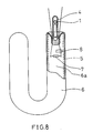
- FIG.8 is a partially cross-sectional side view of the multi-U-bent tube of the first conventional fluorescent lamp.
- the first type of conventional fluorescent lamp comprises d main amalgam 1 and an auxiliary amalgam 8.
- the main amalgam 1 mainly controls the mercury vapor pressure in the predetermined range while the fluorescent lamp is lighted.
- the auxiliary amalgam 8 makes the evaporation of the mercury atoms easy at the beginning of the lighting of the fluorescent lamp.
- the luminance of the first type of conventional fluorescent lamp is maintained at a substantially constant level from the beginning to the end of the lighting.
- the main amalgam 1 is disposed at a predetermined position in a narrow tube 4 in the vicinity of an electrode 7 at an end of the multi-U-bent tube 6.
- the auxiliary amalgam 8 is disposed in the vicinity of an electrode 7 so that it is directly exposed to a discharge space 6a.
- the auxiliary amalgam 8 absorbs some mercury atoms from the main amalgam 1 through the discharge space 6a because the mercury vapor pressure of the auxiliary amalgam 8 is lower than that of the main amalgam 1 at the same temperature.
- the self-ballasted fluorescent lamp replaces the conventional incandescent lamp
- the mounting direction of the fluorescent lamp at the position of the fluorescent lamp is variable.
- the temperature at the position of the amalgam in the multi-U-bent tube changes significantly corresponding to the mounting direction of the fluorescent lamp. Consequently, it is difficult to control the the mercury vapor pressure in a predetermined range from the beginning to the end of the lighting.
- FIG.9 is a partially cross-sectional side view of the multi-U-bent tube of this second type of conventional fluorescent lamp
- FIG.10 is an enlarged cross-sectional side view showing the detailed configuration of container 10 shown in FIG.9.
- a main amalgam 1 is contained in a movable container 10 and the container 10 freely moves in the multi-U-bent tube 6 of the second type of conventional fluorescent lamp.
- the main amalgam 1 contained in the container 10 is always disposed substantially at the lowest position in the multi-U-bent tube 6 against the direction of gravity without relation to the mounting direction of the second conventional fluorescent lamp.
- An auxiliary amalgam 8 is disposed in the vicinity of an electrode 7 where the temperature is higher than that of the main amalgam 1 while the lamp is lighted.
- the auxiliary amalgam 8 absorbs the mercury atoms in the discharge space 6a.
- the auxiliary amalgam 8 releases the mercury atoms at the beginning of the lighting.
- a copper-iron ballast circuit including a glow discharge tube is mainly used.
- the auxiliary amalgam 8 is heated by pre-heating of a filament (electrode 7) while the glow discharge tube operates, so that the mercury atoms are released from the auxiliary amalgam 8.
- the mercury vapor pressure in the discharge space 6a of the multi-U-bent tube 6 quickly increases.
- the time for increasing the luminance of the conventional fluorescent lamp to a predetermined value from the start of the lighting can be shortened.
- the compact self-ballasted fluorescent lamps are required to light instantly, similar to the case of the incandescent lamp.
- an electronic ballast circuit which ignites the fluorescent lamp instantly, is widely used instead of the conventional copper-iron ballast circuit.
- the electronic ballast circuit is used in the conventional fluorescent lamp, the time for pre-heating the filament is too short to heat the auxiliary amalgam 8 to release the mercury atoms. The amount of the mercury atoms released from the auxiliary amalgam 8 due to the heat of the filament is too small. Thus, it is difficult to maintain the mercury vapour pressure at the beginning of the lighting over a predetermined value. The time for increasing the luminance of the lamp to the predetermined value from the start of the lighting becomes longer.
- the main amalgam 1 is contained in the container 10 and most of the surface of the amalgam 1 is exposed to the discharge space 6a through an opening 10a of the container 10.
- the opening 10a of the container 10 permits the mercury atoms in the discharge space 6a to return to the main amalgam 1 in the container 10 because the surface of the main amalgam 1 is large enough to absorb a lot of mercury atoms after switching off of the second type of conventional fluorescent lamp.
- the auxiliary amalgam 8 is also introduced to absorb the mercury atoms easily much better than the main amalgam 1.
- the mercury vapour pressure in the discharge space 6a at the beginning of the re-lighting of the second type of conventional fluorescent lamp cannot be above the predetermined value in case of the combination with the instant start type electronic ballast circuit.
- An objective of this invention is to provide an improved low pressure mercury vapour filled discharge lamp including a compact self-ballasted fluorescent lamp with electrodes and an electrodeless fluorescent lamp, in which the mercury vapor pressure in a discharge space can be maintained in a preferable range from the beginning of the lighting of the lamp, and the time for the luminance of the lamp to reach a predetermined value after switching on the lamp can be shortened.
- the low pressure mercury vapor filled discharge lamp according to this invention is characterized in that the barrier means is a container of which length along a lengthwise direction is larger than the largest width in a direction perpendicular to the lengthwise direction, having only one opening that is formed at an end of the container along the lengthwise direction, and the diameter of the opening is larger than the diameter of a mercury atom but smaller than 0.5 mm provided the opening is represented by a circle of the same area, and an inside wall of the container fits the surface of the amalgam for shielding the amalgam from the discharge space, and a portion of the amalgam that contacts with the discharge space is exposed at the opening of the container.
- the barrier member is provided to contact the amalgam for shielding the amalgam from the discharge space except for at least one opening.
- the opening of the barrier member permits supply of mercury atoms from the amalgam to the discharge space while the lamp is lighted, and keeps the mercury atoms from returning to the amalgam from the discharge space while the amalgam solidifies after the switching off of the lamp.
- any other type of amalgam such as an auxiliary amalgam besides above-mentioned amalgam system is not introduced.
- the amalgam is changed to the liquid phase from the solid phase by heat from a filament, or the like.
- the mercury atoms in the discharge space can be supplied from the amalgam through the opening of the barrier member.
- the luminance of the lamp can be maintained while the lamp is lighted.
- the barrier member restricts the return of the mercury atoms to the amalgam from the discharge space.
- the mercury vapor pressure in the discharge space at the beginning of re-lighting of the lamp is maintained at a value larger than a predetermined value.
- the time to reach the luminance of the lamp to the predetermined value from the beginning of the re-lighting of the lamp becomes shorter, so that a sufficient luminance can be obtained at the beginning of the re-lighting of the lamp.
- the mercury atoms in the discharge space in the lighting can be supplied from the amalgam, so that the mercury vapour pressure in the discharge space can be maintained in a predetermined range while the lamp is lighted. Consequently, a predetermined luminance can be obtained from the beginning to the end of the lighting of the lamp.
- the barrier member is a container having only one opening, and the diameter of the opening is larger than the diameter of the mercury atom but smaller than 0.5 mm provided the opening is represented by a circle having the same area. Also, almost all of the surface of the amalgam contacts the barrier member except the opening.
- the mercury atoms returning to the amalgam are concentrated at a predetermined portion of the surface of the amalgam facing the opening of the container serving as the barrier member.
- the temperature of the lamp becomes lower than the solidification temperature of the amalgam before the mercury atoms in the discharge space return to the amalgam.
- the container is disposed in the vicinity of the coldest portion of the discharge space; the length of the container along a lengthwise direction is larger than the largest width in a direction perpendicular to the lengthwise direction and the opening is formed at an end of the container along the lengthwise direction.
- the surface of the amalgam facing the opening is exposed to a cold condition in the discharge space.
- the temperature at the surface of the amalgam facing the opening becomes lower than that inside the amalgam, so that the surface of the amalgam facing the opening is solidified faster than the inside.
- the time while the mercury atoms adhering on the surface of the amalgam facing the opening can diffuse into the amalgam is shortened while the amalgam solidifies.
- the length of the container is longer than 5 mm and shorter than 15 mm. In such a configuration, the distance from the surface to the bottom of the amalgam in the container is sufficient to prevent the diffusion of the mercury atoms returning from the discharge space evenly while the amalgam is being solidified.
- the end of the container where the opening is formed is disposed away from the electrode.
- a porous filter having a plurality of through holes is provided in the opening of the container, and the diameter of effective part of each through hole is larger than the diameter of the mercury atom provided the area of the through hole is represented by a circle having the same area. This configuration is effective where the opening of the container cannot be made enough smaller to serve as a barrier.
- the porous filter serves as a barrier.
- the porous filter is an aggregate of particles selected from zeolite, porous glass and oxide.
- the particles serve as pseudo-cores for preventing the supercooling of the amalgam.
- the amalgam can be changed from the liquid phase to the solid phase easily.
- the container be made of glass material.
- the container can be formed in a desired shape such as a waterdrop shape. The productibility of the container can be increased and the cost of the container can be reduced.
- the barrier member be a container having a plurality of openings dispersedly provided therein, and the diameter of effective part of each opening is larger than the diameter of the mercury atom provided the area of the opening is represented by a diameter of a circular having the same area but the total area of the openings is smaller than about 0.2 mm 2 .
- the mercury atoms returning to the amalgam are concentrated at predetermined portions of the surface of the amalgam by the openings of the container.
- the returning speed of the mercury atoms to the amalgam becomes slower.
- the temperature of the lamp becomes lower than the solidification temperature of the amalgam before the mercury atoms in the discharge space return to the amalgam. Consequently, a lot of mercury atoms remain in the discharge space.
- the container be made of a porous glass material.
- the through holes of the porous glass serve as the openings.
- the particles of the glass serve as pseudo-cores for preventing the supercooling of the amalgam.
- the amalgam can be changed from the liquid phase to the solid phase easily.
- the barrier member be made of an aggregation of particles coated on a surface of the amalgam and having a plurality of through holes, the diameter of effective part of each through hole being larger than the diameter of the mercury atom provided the area of the through hole is represented by the diameter of a circle having the same area but the total area of the through holes is smaller than about 0.2 mm 2 .
- the aggregation of particles is selected from oxide, zeolite, talc and glass particles.
- the oxide is selected from titanium oxide, aluminum oxide, silicon oxide, magnesium oxide and rare earth metal oxide.
- the particles serve as pseudo-cores for preventing the supercooling of the amalgam.
- the amalgam can be changed from the liquid phase to the solid phase easily.
- a pair of electrodes be provided on both ends of the vessel, and the amalgam is provided in the vicinity of at least one of the pair of electrodes.
- an electro-magnetic energy supplying device is provided from outside of the vessel, and the amalgam is provided at a portion in the discharge space where the magnetic energy is supplied.
- an electrodeless fluorescent lamp in which the amalgam is caused to function by the temperature produced by the electro-magnetic energy supplied from the outside of the vessel for controlling the mercury vapor pressure in the discharge space, can be obtained.
- the base material of the amalgam includes at least one selected from bismuth, indium, tin, zinc and silver.
- the temperature at which the amalgam functions can freely be set by selection of one or combination of these materials.
- the vessel be one selected from the group of a multiply bent tube, a circularly bent tube, a straight tube and a bulb.
- the amalgam system of this invention can be applied in all types of fluorescent lamps on the market.
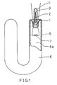
- the fluorescent lamp of the first embodiment includes a multi-U-bent tube (glass vessel) 6, a pair of electrodes (filaments) 7 (one electrode is shown in the figure) and narrow tubes 4 which are provided on both ends of the tube 6.
- a fluorescent layer 5 is formed on an inner surface of the tube 6.
- Amalgam 1 comprises a base material of an alloy of bismuth and indium with 3% of weight of mercury included in the base material.
- the amalgam 1 is contained in the container 2.
- the container 2 serves as a barrier for restricting the movement of mercury atoms between the amalgam 1 and a discharge space 6a inside the tube 6. In other words, the barrier reduces the degree of movement of the mercury atoms.
- an inside wall of the container 2 fits the amalgam 1 for shielding the amalgam 1 from the discharge space 6a.
- the container 2 has a rotationally symmetrical waterdrop shape.
- the length of the container 2 in an axial direction (or a lengthwise direction) is about 10 mm, and the diameter of opening 3 at an end of the container 2 is about 0.1 mm.
- the size of the opening 3 is not restricted by this numerical example.
- the diameter of effective part the opening 3 is larger than the diameter of the mercury atom but smaller than 0.5 mm provided the opening 3 of the container 2 is represented by the diameter of a circle of the same area.
- the container 2 is disposed in the narrow tube 4 in a manner so that the opening 3 is disposed at a lower temperature side far from the electrode 7.
- the inside of the narrow tube 4 is the coldest portion in the discharge space 6a while the lamp has been lighted.
- the area of the opening 3 enables the mercury atoms to be supplied from the amalgam 1 to the discharge space 6a while the fluorescent lamp is being lighted, but prevents to return the mercury atoms from the discharge space 6a to the amalgam 1 while the amalgam 1 has solidified after the fluorescent lamp is switched off.
- the principle of this invention is described below.
- the mercury atoms which exist in the discharge space 6a at a preferable vapour pressure while the fluorescent lamp is being lighted, start to return to the amalgam 1 corresponding to the reduction of the temperature after switching off of the fluorescent lamp.
- the amalgam 1 in the container 2 is exposed to the discharge space 6a only at the opening 3.
- the area of the opening 3 is very small.
- the degree of movement of the mercury atoms is very small, so that the amalgam 1 has solidified before a lot of mercury atoms return to the amalgam 1.
- the diffusing speed of the mercury atoms into the amalgam becomes very slow.
- the mercury atoms adhere on only the minute surface of the amalgam 1 at the opening 3.
- the density of the mercury atoms at the boundary between the amalgam 1 and the discharge space 6a becomes much higher than that in the other part, so that the mercury vapour pressure in the vicinity of the boundary increases.
- the reduction of the mercury atoms in the discharge space 6a can be reduced. Consequently, the luminance of the fluorescent lamp of the first embodiment can be increased at the beginning of re-lighting of the lamp.
- a prototype of the fluorescent lamp of the first embodiment was manufactured and the relative luminous flux of the fluorescent lamp at the beginning of the re-lighting was measured.
- the first type of conventional fluorescent lamp shown in FIG.8 and a reference fluorescent lamp without amalgam and auxiliary amalgam but filled with mercury vapour were prepared.
- the relative luminous flux of these comparative examples at the beginning of the re-lighting were also measured.
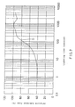
- the results of the measurements are shown in FIG.6.
- the abscissa represents a time from the start of the lighting of the lamps, and the ordinate represents the relative luminous flux (%) of each fluorescent lamp at a time of measurement against the maximum intensity of the luminance of the fluorescent lamp.
- Characteristic curve "A” represents the relative luminous flux of the fluorescent lamp of the first embodiment of this invention.
- Characteristic curve “B” represents the relative luminous flux of the conventional fluorescent lamp.
- Characteristic curve “C” represents the relative luminous flux of the referential fluorescent lamp.
- Each fluorescent lamp comprises an electronic ballast circuit excluding pre-heating mode of the filament. Each fluorescent lamp was once lighted for several hours. After that, each fluorescent lamp was re-lighted at ambient temperature of 25°C, after fifteen hours had passed after the switching off of the fluorescent lamp.
- the characteristic curve "A” according to the fluorescent lamp of the first embodiment of this invention starts from about 50% of the relative luminous flux.
- the characteristic curve "B” according to the conventional fluorescent lamp starts about 20% of the relative luminous flux, since the mercury vapor pressure due to the main amalgam 1 and the auxiliary amalgam 8 is lower at the beginning of the re-lighting.
- the fluorescent lamp of the first embodiment can maintain substantially the maximum luminous flux.
- the conventional fluorescent lamp can maintain substantially the maximum luminous flux.
- the characteristic curve "C” according to the reference fluorescent lamp starts from about 60% of the relative luminous flux.
- the relative luminous flux of the referential fluorescent lamp decreases after reaching the maximum luminous flux, since the mercury vapour pressure increases to a level above the most preferable pressure after passing the maximum luminous flux.
- the reason why the relative intensity of the luminance of the fluorescent lamp of the first embodiment was increased at the beginning of the re-lighting is considered.
- the amalgam 1 in the container 2 was changed to the liquid phase at a temperature about 120 degrees Celsius.
- the mercury atoms evenly exist in the amalgam 1, and the mercury is equilibrated between the vapor phase and the liquid phase at the boundary between the amalgam 1 and the discharge space 6a at the opening 3 of the container 2.
- the mercury vapour pressure in the discharge space was maintained at substantially the best condition, so that substantially the maximum intensity of the luminance has been obtained.
- the same amount of the mercury atoms as needed in the discharge space 6a of the tube 6 is supplied from the amalgam 1.
- the mercury atoms will return to the amalgam 1 directly through the opening 3 as repeating the cycle between adhering on and releasing from the side wall of the container 2 where the temperature and the mercury vapour pressure are reduced.
- the diameter of the opening 3 of the container 2 is about 0.1 mm when the opening 3 is converted as circular, the conductance of the movement of the mercury atoms is too small.
- the amalgam 1 is in the liquid phase, only a part of the mercury atoms existed in the discharge space can return to the amalgam 1. The mercury atoms adhered on the surface of the amalgam 1 in the liquid phase can easily diffuse into the amalgam 1.
- the diffusion rate of the mercury atoms into the amalgam 1 suddenly decreases.
- the mercury atoms reaching after the solidification of the amalgam 1 deposit and adhere on the surface of the amalgam 1.
- the area of the surface of the amalgam 1 exposed to the discharge space 6a is small, so that the density of the mercury adhered on the surface of the amalgam 1 suddenly increases.
- the mercury vapour pressure in the vicinity of the surface of the amalgam 1 becomes substantially equal to the mercury vapor pressure in the vicinity of the surface of the wall of the container 2, the movement of the mercury atoms stops.
- most of the mercury atoms existing in the discharge space 6a during the lighting of the fluorescent lamp continue to exist in the discharge space 6a including the wall of the container 2.
- the above-mentioned first embodiment is explained referring to the numerical example that the diameter of the opening 3 of the container 2 is about 0.1 mm provided the area of the opening 3 is represented by the diameter of a circle of the same area.
- the relative luminous flux at the beginning of the re-lighting of the lamp can be increased.
- the diameter of the opening 3 of the container 2 is about 0.5 mm provided the opening 3 is represented by the diameter of a circle of the same area
- the relative luminous flux at the beginning of the re-lighting of the fluorescent lamp can be made higher than that of the conventional fluorescent lamp.
- the manufacture of the container 2 becomes difficult and the cost will be increased, but the relative luminous flux of the fluorescent lamp at the beginning of the re-lighting becomes much higher than the conventional fluorescent lamp.
- the container 2 can be manufactured relatively easier, but the relative luminous flux of the fluorescent lamp at the beginning of the re-lighting is relatively lower than the former case.
- the choice between the two is based on the purpose and cost performance of the fluorescent lamp.
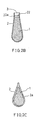
- a porous filter 22 having a plurality of through holes 22a to contact the surface of the amalgam 1 except for the through holes 22a in the opening 3 of the container 2.
- Each hrough hole 22a of the porous filter 22 has an effective diameter larger than the diameter of the mercury atom provided the through holes are represented by the diameter of a circle of the same area.
- the material of the porous filter 22 is selected from zeolite, porous glass and oxide particle such as titanium oxide, aluminum oxide, silicon oxide, magnesium oxide or rare earth metal oxide.
- porous filter 22 is disposed to contact the surface of the amalgam 1, so that the particles of the porous filter 22 serve as pseudo-cores for preventing supercooling of the amalgam 1. Consequently, the change of the amalgam 1 from the liquid phase to the solid phase can be made easier (see the publication gazette of unexamined Japanese patent application Sho 63-284748).
- These functions of the porous filter 22 are effective to maintain the amount of the mercury atoms which are to remain in the discharge space, and to increase the relative luminous flux of the fluorescent lamp at the beginning of the re-lighting.
- the container 2 be made of porous glass.
- the container 2 has a plurality of through holes 2a, similar to the porous filter 22 shown in FIG.2B.
- the through holes of the container 2 permit to move the mercury atoms from the amalgam 1 to the discharge space 6a in the multi-U-bent tube 6, but restrict to return the mercury atoms from the discharge space 6a to the amalgam 1 in a short time while the amalgam 1 solidifies.
- effects which are substantially the same as those of the porous filter 12 shown in FIG.2B can be obtained.
- the base material of the amalgam 1 is not restricted by the above-mentioned example of the alloy of bismuth and indium. It is preferable that an alloy of the base material includes one or more kind of metals selected from bismuth, indium, tin, lead, zinc and silver. By selecting the material of the base material of the amalgam 1, the temperature at which the amalgam changes phase can be selected desirably.
- the fluorescent lamp of the second embodiment comprises a multi-U-bent tube 6, a pair of electrodes (filaments) 7 (one electrode is shown in the figure) and narrow tubes 4 which are provided on both ends of the tube 6.
- a fluorescent layer 5 is formed on an inner surface of the tube 6.
- a glass rod 11 and an amalgam 1 are disposed in series in the narrow tube 4 from the electrode 7.
- Amalgam 1 consists of a base material of an alloy of bismuth and indium and about 3 wt% mercury included in the base material.
- the amalgam 1 has substantially a ball shape.
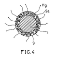
- an aggregation of particles 9 is coated on the surface of the amalgam 1.
- the aggregation of the particles 9 serves as a barrier for restricting the movement of the mercury atoms between the amalgam 1 and the discharge space 6a inside the tube 6 corresponding to switching on and off the fluorescent lamp.
- the aggregation of the particles 9 is, for example, is formed by spreading a suspension of talc dispersed in volatile solvent on the surface of the amalgam 1.
- An average particle diameter of the aggregation of particles 9 is about 0.1 ⁇ m and the quantity of the adhered particles is about 1 mg/cm 2 .
- the aggregation of particles 9 has a plurality of through holes 9a dispersedly formed.
- An effective diameter of each through hole (9a) is larger than the diameter of a mercury atom provided the through hole 9a is represented by the diameter of a circle of the same area but the total area of the through holes is smaller than about 0.2 mm 2 .
- FIG.7 A prototype of the fluorescent lamp of the second embodiment was manufactured and the relative luminous flux at the beginning of the re-lighting was measured. The result is shown in FIG.7.
- the abscissa represents a time from the start of the lighting of the lamps, and the ordinate represents the relative luminous flux (%) of the fluorescent lamp at a time of measurement against the maximum luminous flux of the fluorescent lamp.
- Characteristic curve "D" represents the relative luminous flux of the fluorescent lamp of the second embodiment of this invention.
- the fluorescent lamp comprises an electronic ballast circuit excluding pre-heating mode of the filament. The fluorescent lamp was once lighted for several hours. After that, the fluorescent lamp was re-lighted at ambient temperature of 25°C after fifteen hours had passed after the switching off of the fluorescent lamp.
- characteristic curve "D" according to the fluorescent lamp of the second embodiment of this invention starts from about 40% of the relative luminous flux.
- characteristic curve "B" according to the conventional fluorescent lamp starts about 20% of the relative luminous flux, since the mercury vapor pressure due to the main amalgam 1 and the auxiliary amalgam 8 is lower at the beginning of the re-lighting.
- the relative luminous flux at the beginning of the re-lighting of the fluorescent lamp of the second embodiment is increased.
- the aggregation of particles 9 coated on the surface of the amalgam 1 can serve as the barrier for restricting the movement of the mercury atoms between the amalgam 1 and the discharge space 6a.
- the material of the aggregation particles 9 is not restricted to the above-mentioned example of talc.
- talc one selected from zeolite, glass powder and oxide particles such as titanium oxide, aluminum oxide, silicon oxide, magnesium oxide and rare earth metal oxide can be used.
- the electrodeless type fluorescent lamp of the third embodiment comprises a bulb (glass vessel) 16, a narrow tube 4 disposed at the center of the bulb 16, and a coil 12 wound around the outside of the narrow tube 4.
- a fluorescent layer 5 is formed on an inside face of the bulb 16.
- the center part of the bulb 16 is hollow, and the narrow tube 4 is connected to an inner discharge space 16a of the bulb 16.
- the coil 12 supplies electro-magnetic energy into the discharge space 16a.
- Container 2 which is, for example, made of glass, is disposed inside the narrow tube 4.
- Amalgam 1 consisting of a base material of an alloy of bismuth and indium and about 3 wt% mercury included in the base material is contained in the container 2.
- the container 2 serves as a barrier for restricting the movement of mercury atoms between the amalgam 1 and the inner discharge space 16a of the bulb 16. In other words, the barrier reduces the degree of movement of the mercury atoms.
- an inside wall of the container 2 fits the amalgam 1 for shielding the amalgam 1 from the discharge space 16a.
- the container 2 has a rotationally symmetrical waterdrop shape.
- a length of the container 2 in an axial direction (or a lengthwise direction) is about 10 mm, and the diameter of opening 3 at an end of the container 2 is about 0.1 mm.
- the size of the opening 3 is not restricted by this example.
- the container 2 is disposed in the narrow tube 4 in a manner so that the opening 3 is disposed at a lower temperature side far from the coil 12.
- the third embodiment is described referring to the example of the amalgam 1 contained in the container 2 similar to the first embodiment.
- the amalgam 1 is not restricted by this example. It is preferable that the an aggregation of particles of oxide is coated on the surface of the amalgam similar to the second embodiment.
- the container 2 is made of porous glass. Alternatively, a porous filter can be disposed at the opening 3 of the container 2.
- the above-mentioned embodiments of the low pressure mercury vapor filled discharge lamp are explained referring to multi-U-bent type tube or bulb.
- the amalgam system of this invention in which the barrier means is provided to contact the surface of the amalgam for shielding the amalgam 1 from the discharge space except for the opening or through holes, is effective in a straight fluorescent lamp and a circular fluorescent lamp.
Landscapes
- Discharge Lamp (AREA)
- Vessels And Coating Films For Discharge Lamps (AREA)
Claims (16)
- Niederdruckquecksilberdampfentladungslampe, die folgendes umfaßt: ein Gefäß (6, 16), deren Innenfläche mit einer Fluoreszenzschicht (5) beschichtet ist, ein Amalgam (1) einschließlich Quecksilber als primäres Amalgam, das an einer vorbestimmten Position in einem in dem Gefäß ausgebildeten Entladungsraum (6a, 16a) angeordnet ist, und ein Sperrmittel (2, 9, 22) zum Einschränken der Bewegung von Quecksilberatomen zwischen dem Amalgam (1) und dem Entladungsraum (6a, 16a), wobei die Lampe ein- und ausgeschaltet werden kann;
wobei das Gefäß außer dem primären Amalgam kein Amalgam enthält, wobei das Sperrmittel (2, 9, 22) zum Kontaktieren des Amalgams (1) vorgesehen ist, um das Amalgam (1) von dem Entladungsraum (6a, 16a) mit Ausnahme mindestens einer Öffnung (2a, 3, 9a, 22a) abzuschirmen und die Öffnung (2a, 3, 9a, 22a) des Sperrmittels (2, 9, 22) die Zufuhr der Quecksilberatome von dem Amalgam (1) zu dem Entladungsraum (6a, 16a) gestattet, während die Lampe leuchtet, und die Rückkehr von Quecksilberatomen von dem Entladungsraum (6a, 16a) zu dem Amalgam (1) nach dem Ausschalten der Lampe einschränkt,
dadurch gekennzeichnet, daß das Sperrmittel ein Behälter (2) ist, dessen Länge in einer Längsrichtung größer ist als die größte Breite in einer Richtung senkrecht zu der Längsrichtung,nur eine Öffnung (3) aufweist, die an einem Ende des Behälters entlang der Längsrichtung ausgebildet ist, und ein Durchmesser der Öffnung (3) größer ist alsder Durchmesser eines Quecksilberatoms, aber kleiner als 0,5 mm, vorausgesetzt, die Öffnung (3) wird durch einen Kreis mit dem gleichen Flächeninhalt dargestellt,und eine Innenwand des Behälters (2) zu der Oberfläche des Amalgams (1) paßt, um das Amalgam von dem Entladungsraum abzuschirmen, und ein Teil des Amalgams (1), das den Entladungsraum kontaktiert, an der Öffnung (3) des Behälters (2) freiliegt. - Niederdruckquecksilberdampfentladungslampe nach Anspruch 1, bei der an jeweiligen Enden des Gefäßes (6) ein Paar Elektroden (7) vorgesehen ist und das Amalgam (1) in der Nähe mindestens einer des Paares von Elektroden (7) vorgesehen ist.
- Niederdruckquecksilberdampfentladungslampe nach Anspruch 1, weiterhin mit einem elektromagnetische Energie liefernden Mittel (12), das außerhalb des Gefäßes (16) angeordnet ist, und bei dem das Amalgam (1) an einem Teil in dem Entladungsraum (16a) angeordnet ist, wo die elektromagnetische Energie geliefert wird.
- Niederdruckquecksilberdampfentladungslampe nach einem der Ansprüche 1 bis 3, bei der der Behälter (2) in der Nähe des kältesten Teils des Entladungsraums (6a, 16a) angeordnet ist und die Öffnung (3) an einem Ende des Behälters (2) entlang der Längsrichtung ausgebildet ist.
- Niederdruckquecksilberdampfentladungslampe nach Anspruch 4, bei der der Behälter (2) länger als 5 mm und kürzer als 15 mm ist.
- Niederdruckquecksilberdampfentladungslampe nach Anspruch 4, bei der dasjenige Ende des Behälters (2), an dem die Öffnung (3) ausgebildet ist, von der Elektrode (7) entfernt angeordnet ist.
- Niederdruckquecksilberdampfentladungslampe nach einem in der Ansprüche 1 bis 6, bei der der Behälter (2) aus Glasmaterial hergestellt ist.
- Niederdruckquecksilberdampfentladungslampe nach einem der Ansprüche 1 bis 7, bei der in der Öffnung (3) des Behälters (2) ein poröser Filter (22) mit mehreren Durchgangslöchern (22a) vorgesehen ist und ein Durchmesser jedes Durchgangslochs (22a) größer ist als der Durchmesser eines Quecksilberatoms, vorausgesetzt, das Durchgangsloch wird durch einen Kreis mit dem gleichen Flächeninhalt dargestellt.
- Niederdruckquecksilberdampfentladungslampe nach Anspruch 8, bei der der poröse Filter (22) eine Anhäufung von Teilchen ausgewählt aus der Gruppe bestehend aus Zeolith, porösem Glas und Oxidteilchen ist.
- Niederdruckquecksilberdampfentladungslampe, die folgendes umfaßt: ein Gefäß (6, 16), deren Innenfläche mit einer Fluoreszenzschicht (5) beschichtet ist, ein Amalgam (1) einschließlich Quecksilber als primäres Amalgam, das an einer vorbestimmten Position in einem in dem Gefäß ausgebildeten Entladungsraum (6a, 16a) angeordnet ist, und ein Sperrmittel (2, 9, 22) zum Einschränken der Bewegung von Quecksilberatomen zwischen dem Amalgam (1) und dem Entladungsraum (6a, 16a), wobei die Lampe ein- und ausgeschaltet werden kann;wobei das Gefäß außer dem primären Amalgam kein Amalgam enthält, wobei das Sperrmittel (2, 9, 22) zum Kontaktieren des Amalgams (1) vorgesehen ist, um das Amalgam (1) von dem Entladungsraum (6a, 16a) mit Ausnahme mindestens einer Öffnung (2a, 3, 9a, 22a) abzuschirmen und die Öffnung (2a, 3, 9a, 22a) des Sperrmittels (2, 9, 22) die Zufuhr der Quecksilberatome von dem Amalgam (1) zu dem Entladungsraum (6a, 16a) gestattet, während die Lampe leuchtet, und die Rückkehr von Quecksilberatomen von dem Entladungsraum (6a, 16a) zu dem Amalgam (1) nach dem Ausschalten der Lampe einschränkt,bei der das Sperrmittel ein Behälter (2) mit mehreren verteilt vorgesehenen Öffnungen ist, dadurch gekennzeichnet, daß der Durchmesser jeder Öffnung (2a) größer ist als der Durchmesser eines Quecksilberatoms, vorausgesetzt, die Öffnung (2a) wird durch einen Kreis mit dem gleichen Flächeninhalt dargestellt, aber der Gesamtflächeninhalt der Öffnungen (2a) ist kleiner als etwa 0,2 mm2.
- Niederdruckquecksilberdampfentladungslampe nach Anspruch 10, bei der der Behälter (2) aus einem porösen Glasmaterial hergestellt ist.
- Niederdruckquecksilberdampfentladungslampe, die folgendes umfaßt: ein Gefäß (6, 16), deren Innenfläche mit einer Fluoreszenzschicht (5) beschichtet ist, ein Amalgam (1) einschließlich Quecksilber als primäres Amalgam, das an einer vorbestimmten Position in einem in dem Gefäß ausgebildeten Entladungsraum (6a, 16a) angeordnet ist, und ein Sperrmittel (2, 9, 22) zum Einschränken der Bewegung von Quecksilberatomen zwischen dem Amalgam (1) und dem Entladungsraum (6a, 16a), wobei die Lampe ein- und ausgeschaltet werden kann;wobei das Gefäß außer dem primären Amalgam kein Amalgam enthält, wobei das Sperrmittel (2, 9, 22) zum Kontaktieren des Amalgams (1) vorgesehen ist, um das Amalgam (1) von dem Entladungsraum (6a, 16a) mit Ausnahme mindestens einer Öffnung (2a, 3, 9a, 22a) abzuschirmen und die Öffnung (2a, 3, 9a, 22a) des Sperrmittels (2, 9, 22) die Zufuhr der Quecksilberatome von dem Amalgam (1). zu dem Entladungsraum (6a, 16a) gestattet, während die Lampe leuchtet, und die Rückkehr von Quecksilberatomen von dem Entladungsraum (6a, 16a) zu dem Amalgam (1) nach dem Ausschalten der Lampe einschränkt,bei der das Sperrmittel (9) aus einer Anhäufung von Teilchen hergestellt ist, mit der eine Oberfläche des Amalgams (1) beschichtet ist, dadurch gekennzeichnet, daß ein Durchmesser jedes Durchgangslochs (9a) größer ist als der Durchmesser eines Quecksilberatoms, vorausgesetzt, das Durchgangsloch (9a) wird durch einen Kreis mit dem gleichen Flächeninhalt dargestellt, aber der Gesamtflächeninhalt der Durchgangslöcher (9a) ist kleiner als etwa 0,2 mm2.
- Niederdruckquecksilberdampfentladungslampe nach Anspruch 12, bei der die Anhäufung von Teilchen (9) ausgewählt ist aus der Gruppe bestehend aus Oxid, Zeolith, Talk und Glasteilchen.
- Niederdruckquecksilberdampfentladungslampe nach Anspruch 13, bei der das Oxid ausgewählt ist aus der Gruppe bestehend aus Titanoxid, Aluminiumoxid, Siliziumoxid, Magnesiumoxid und Seltenerdmetalloxid.
- Niederdruckquecksilberdampfentladungslampe nach einem der Ansprüche 1 bis 14, bei der das Basismaterial des Amalgams (1) mindestens ein Element ausgewählt aus der Gruppe bestehend aus Bismut, Indium, Zinn, Zink und Silber ist.
- Niederdruckquecksilberdampfentladungslampe nach einem der Ansprüche 1 bis 15, bei der das Gefäß (6, 16) eines ist, das ausgewählt ist aus der Gruppe bestehend aus mehrfach gebogenem Rohr, einem kreisförmig gebogenem Rohr, einem geraden Rohr und einem Kolben.
Priority Applications (4)
| Application Number | Priority Date | Filing Date | Title |
|---|---|---|---|
| CA002177108A CA2177108C (en) | 1996-05-22 | 1996-05-22 | Low pressure mercury vapor filled discharge lamp |
| US08/652,909 US5828169A (en) | 1996-05-22 | 1996-05-23 | Discharge lamp having an amalgam within a barrier means |
| EP96108251A EP0809276B1 (de) | 1996-05-22 | 1996-05-23 | Quecksilberdampfgefüllte Niederdruckentladungslampe |
| DE1996614246 DE69614246T2 (de) | 1996-05-23 | 1996-05-23 | Quecksilberdampfgefüllte Niederdruckentladungslampe |
Applications Claiming Priority (3)
| Application Number | Priority Date | Filing Date | Title |
|---|---|---|---|
| CA002177108A CA2177108C (en) | 1996-05-22 | 1996-05-22 | Low pressure mercury vapor filled discharge lamp |
| US08/652,909 US5828169A (en) | 1996-05-22 | 1996-05-23 | Discharge lamp having an amalgam within a barrier means |
| EP96108251A EP0809276B1 (de) | 1996-05-22 | 1996-05-23 | Quecksilberdampfgefüllte Niederdruckentladungslampe |
Publications (2)
| Publication Number | Publication Date |
|---|---|
| EP0809276A1 EP0809276A1 (de) | 1997-11-26 |
| EP0809276B1 true EP0809276B1 (de) | 2001-08-01 |
Family
ID=27170150
Family Applications (1)
| Application Number | Title | Priority Date | Filing Date |
|---|---|---|---|
| EP96108251A Expired - Lifetime EP0809276B1 (de) | 1996-05-22 | 1996-05-23 | Quecksilberdampfgefüllte Niederdruckentladungslampe |
Country Status (3)
| Country | Link |
|---|---|
| US (1) | US5828169A (de) |
| EP (1) | EP0809276B1 (de) |
| CA (1) | CA2177108C (de) |
Families Citing this family (15)
| Publication number | Priority date | Publication date | Assignee | Title |
|---|---|---|---|---|
| US6456004B1 (en) | 1999-09-10 | 2002-09-24 | General Electric Company | Fluorescent lamp having uniquely configured container containing amalgam for regulating mercury vapor equilibrium |
| JP3395750B2 (ja) * | 2000-02-16 | 2003-04-14 | 松下電器産業株式会社 | 蛍光ランプおよびその製造方法 |
| US6310437B1 (en) * | 2000-06-01 | 2001-10-30 | General Electric Company | Fluorescent lamp extension tube amalgam holder |
| US6787980B2 (en) | 2000-09-22 | 2004-09-07 | Matsushita Electric Industrial Co., Ltd. | Mercury-containing material, method for producing the same and fluorescent lamp using the same |
| US6849998B2 (en) * | 2000-12-12 | 2005-02-01 | Osram Sylvania Inc. | Amalgam retainer |
| US7164224B2 (en) * | 2000-12-14 | 2007-01-16 | Sharp Kabushiki Kaisha | Backlight having discharge tube, reflector and heat conduction member contacting discharge tube |
| DE102006033674A1 (de) * | 2006-07-20 | 2008-01-24 | Patent-Treuhand-Gesellschaft für elektrische Glühlampen mbH | Entladungslampe mit einem Entladungsgefäß |
| DE102006052953A1 (de) * | 2006-11-09 | 2008-05-15 | Patent-Treuhand-Gesellschaft für elektrische Glühlampen mbH | Entladungslampe mit einem Entladungsgefäß und einem mit dem Entladungsgefäß verbundenen Röhrenstück |
| PL1985717T3 (pl) * | 2007-04-28 | 2011-11-30 | Umicore Ag & Co Kg | Kulki amalgamatu do lamp energooszczędnych i ich wytwarzanie |
| US7812533B2 (en) | 2007-11-09 | 2010-10-12 | Osram Sylvania Inc. | Mercury dispenser, method of making mercury dispenser and method of dosing mercury into ARC discharge lamp |
| US8378571B2 (en) * | 2007-11-09 | 2013-02-19 | Osram Sylvania Inc. | Precision mercury dispenser using wire |
| CN102005353B (zh) * | 2010-09-28 | 2011-12-28 | 泰州市华强照明器材有限公司 | 内置汞齐阻挡件的节能灯芯柱的制造方法 |
| EP2497841B1 (de) | 2011-03-09 | 2015-09-02 | Umicore AG & Co. KG | Sn-Ag-Cu-Legierungen |
| DE102011079776A1 (de) * | 2011-07-26 | 2013-01-31 | Osram Ag | Gasentladungslampe und Verfahren zum Herstellen einer Gasentladungslampe |
| CN112017943B (zh) * | 2020-09-04 | 2022-07-01 | 深圳柯维紫外技术有限公司 | 一种提高低压汞放电灯环境适应性的方法、汞合金配方、制造方法、及其紫外线灯 |
Citations (1)
| Publication number | Priority date | Publication date | Assignee | Title |
|---|---|---|---|---|
| JPS60154451A (ja) * | 1984-01-24 | 1985-08-14 | Toshiba Corp | 低圧水銀蒸気放電灯 |
Family Cites Families (12)
| Publication number | Priority date | Publication date | Assignee | Title |
|---|---|---|---|---|
| GB1419099A (en) * | 1972-08-11 | 1975-12-24 | Thorn Electrical Ind Ltd | Manufacturing electric devices having sealed envelopes |
| US4020378A (en) * | 1972-09-28 | 1977-04-26 | Westinghouse Electric Corporation | Integral mercury-vapor pressure regulating means for fluorescent lamp |
| JPS60202652A (ja) * | 1984-03-27 | 1985-10-14 | Toshiba Corp | 低圧水銀蒸気放電灯 |
| JPS6264044A (ja) * | 1985-09-13 | 1987-03-20 | Matsushita Electronics Corp | 電球形蛍光ランプ |
| JPH083997B2 (ja) * | 1988-12-12 | 1996-01-17 | 東芝ライテック株式会社 | 低圧水銀蒸気放電灯 |
| DE3907277A1 (de) * | 1989-03-07 | 1990-09-20 | Patent Treuhand Ges Fuer Elektrische Gluehlampen Mbh | Quecksilberniederdruckentladungslampe |
| US5204584A (en) * | 1990-09-28 | 1993-04-20 | Toshiba Lighting & Technology Corporation | Low pressure mercury vapor discharge lamp |
| US5274305A (en) * | 1991-12-04 | 1993-12-28 | Gte Products Corporation | Low pressure mercury discharge lamp with thermostatic control of mercury vapor pressure |
| US5294867A (en) * | 1992-03-13 | 1994-03-15 | Gte Products Corporation | Low pressure mercury vapor discharge lamp containing an amalgam |
| CA2091470A1 (en) * | 1992-04-28 | 1993-10-29 | Katherine L. Mcginnis | Method and apparatus for introducing mercury into arc discharge lamps |
| EP0646942B1 (de) * | 1993-10-04 | 1997-06-04 | General Electric Company | Genaue Plazierung und Halterung eines Amalgams in einer elektrodenlose Leuchtstofflampe |
| US5412289A (en) * | 1993-12-15 | 1995-05-02 | General Electric Company | Using a magnetic field to locate an amalgam in an electrodeless fluorescent lamp |
-
1996
- 1996-05-22 CA CA002177108A patent/CA2177108C/en not_active Expired - Fee Related
- 1996-05-23 US US08/652,909 patent/US5828169A/en not_active Expired - Fee Related
- 1996-05-23 EP EP96108251A patent/EP0809276B1/de not_active Expired - Lifetime
Patent Citations (1)
| Publication number | Priority date | Publication date | Assignee | Title |
|---|---|---|---|---|
| JPS60154451A (ja) * | 1984-01-24 | 1985-08-14 | Toshiba Corp | 低圧水銀蒸気放電灯 |
Also Published As
| Publication number | Publication date |
|---|---|
| CA2177108A1 (en) | 1997-11-23 |
| EP0809276A1 (de) | 1997-11-26 |
| CA2177108C (en) | 2002-10-22 |
| US5828169A (en) | 1998-10-27 |
Similar Documents
| Publication | Publication Date | Title |
|---|---|---|
| EP0809276B1 (de) | Quecksilberdampfgefüllte Niederdruckentladungslampe | |
| JPS6221223B2 (de) | ||
| US4972118A (en) | Amalgam having extended stable mercury vapor pressure range and low mercury vapor pressure discharge lamp using the same | |
| JP3027006B2 (ja) | 水銀・亜鉛アマルガムを含む蛍光灯及びその製造方法 | |
| JPH09185955A (ja) | 無電極蛍光ランプ | |
| JP4205161B2 (ja) | 低圧水銀蒸気放電ランプ | |
| WO1996002936A1 (en) | Low-pressure mercury vapour discharge lamp | |
| US20040056583A1 (en) | Fluorescent lamp and amalgam assembly therefor | |
| US6650041B1 (en) | Fluorescent lamp and amalgam assembly therefor | |
| JP3380615B2 (ja) | 短アーク放電灯 | |
| CN1090811C (zh) | 充有低压汞蒸汽的放电灯 | |
| KR101036746B1 (ko) | 형광램프 및 아말감 조립체 | |
| US6653775B1 (en) | Fluorescent lamp and amalgam assembly therefor | |
| US6784609B2 (en) | Fluorescent lamp and amalgam assembly therefor | |
| JPS62110251A (ja) | 金属蒸気放電ランプ用のアーク管 | |
| JP3016705B2 (ja) | 蛍光ランプ | |
| JPH09320520A (ja) | 蛍光ランプ | |
| JPH09320523A (ja) | 無電極型放電ランプ | |
| HK1005527B (en) | Low pressure mercury vapor filled discharge lamp | |
| JPS61232549A (ja) | 螢光ランプ | |
| JPH10302718A (ja) | 低圧水銀放電ランプ | |
| JPH09223482A (ja) | 電球形蛍光ランプ | |
| JPH02236945A (ja) | 低圧水銀蒸気放電灯 | |
| JPS60202652A (ja) | 低圧水銀蒸気放電灯 | |
| JPH0447894Y2 (de) |
Legal Events
| Date | Code | Title | Description |
|---|---|---|---|
| PUAI | Public reference made under article 153(3) epc to a published international application that has entered the european phase |
Free format text: ORIGINAL CODE: 0009012 |
|
| 17P | Request for examination filed |
Effective date: 19970124 |
|
| AK | Designated contracting states |
Kind code of ref document: A1 Designated state(s): DE NL |
|
| GRAG | Despatch of communication of intention to grant |
Free format text: ORIGINAL CODE: EPIDOS AGRA |
|
| GRAG | Despatch of communication of intention to grant |
Free format text: ORIGINAL CODE: EPIDOS AGRA |
|
| GRAG | Despatch of communication of intention to grant |
Free format text: ORIGINAL CODE: EPIDOS AGRA |
|
| GRAH | Despatch of communication of intention to grant a patent |
Free format text: ORIGINAL CODE: EPIDOS IGRA |
|
| GRAA | (expected) grant |
Free format text: ORIGINAL CODE: 0009210 |
|
| AK | Designated contracting states |
Kind code of ref document: B1 Designated state(s): DE NL |
|
| REF | Corresponds to: |
Ref document number: 69614246 Country of ref document: DE Date of ref document: 20010906 |
|
| NLS | Nl: assignments of ep-patents |
Owner name: MATSUSHITA ELECTRIC INDUSTRIAL CO., LTD. |
|
| PGFP | Annual fee paid to national office [announced via postgrant information from national office to epo] |
Ref country code: DE Payment date: 20020529 Year of fee payment: 7 |
|
| PLBE | No opposition filed within time limit |
Free format text: ORIGINAL CODE: 0009261 |
|
| STAA | Information on the status of an ep patent application or granted ep patent |
Free format text: STATUS: NO OPPOSITION FILED WITHIN TIME LIMIT |
|
| 26N | No opposition filed | ||
| PG25 | Lapsed in a contracting state [announced via postgrant information from national office to epo] |
Ref country code: DE Free format text: LAPSE BECAUSE OF NON-PAYMENT OF DUE FEES Effective date: 20031202 |
|
| PGFP | Annual fee paid to national office [announced via postgrant information from national office to epo] |
Ref country code: NL Payment date: 20050503 Year of fee payment: 10 |
|
| PG25 | Lapsed in a contracting state [announced via postgrant information from national office to epo] |
Ref country code: NL Free format text: LAPSE BECAUSE OF NON-PAYMENT OF DUE FEES Effective date: 20061201 |
|
| NLV4 | Nl: lapsed or anulled due to non-payment of the annual fee |
Effective date: 20061201 |