EP0809284A1 - Verfahren und anordnung zur überbringung dünner substrate vom plattentyp - Google Patents
Verfahren und anordnung zur überbringung dünner substrate vom plattentyp Download PDFInfo
- Publication number
- EP0809284A1 EP0809284A1 EP96942663A EP96942663A EP0809284A1 EP 0809284 A1 EP0809284 A1 EP 0809284A1 EP 96942663 A EP96942663 A EP 96942663A EP 96942663 A EP96942663 A EP 96942663A EP 0809284 A1 EP0809284 A1 EP 0809284A1
- Authority
- EP
- European Patent Office
- Prior art keywords
- tunnel
- gas
- wafers
- detection system
- substrate wafers
- Prior art date
- Legal status (The legal status is an assumption and is not a legal conclusion. Google has not performed a legal analysis and makes no representation as to the accuracy of the status listed.)
- Granted
Links
Images


Classifications
-
- H—ELECTRICITY
- H10—SEMICONDUCTOR DEVICES; ELECTRIC SOLID-STATE DEVICES NOT OTHERWISE PROVIDED FOR
- H10P—GENERIC PROCESSES OR APPARATUS FOR THE MANUFACTURE OR TREATMENT OF DEVICES COVERED BY CLASS H10
- H10P72/00—Handling or holding of wafers, substrates or devices during manufacture or treatment thereof
- H10P72/50—Handling or holding of wafers, substrates or devices during manufacture or treatment thereof for positioning, orientation or alignment
-
- H—ELECTRICITY
- H10—SEMICONDUCTOR DEVICES; ELECTRIC SOLID-STATE DEVICES NOT OTHERWISE PROVIDED FOR
- H10P—GENERIC PROCESSES OR APPARATUS FOR THE MANUFACTURE OR TREATMENT OF DEVICES COVERED BY CLASS H10
- H10P72/00—Handling or holding of wafers, substrates or devices during manufacture or treatment thereof
- H10P72/06—Apparatus for monitoring, sorting, marking, testing or measuring
- H10P72/0604—Process monitoring, e.g. flow or thickness monitoring
-
- G—PHYSICS
- G03—PHOTOGRAPHY; CINEMATOGRAPHY; ANALOGOUS TECHNIQUES USING WAVES OTHER THAN OPTICAL WAVES; ELECTROGRAPHY; HOLOGRAPHY
- G03F—PHOTOMECHANICAL PRODUCTION OF TEXTURED OR PATTERNED SURFACES, e.g. FOR PRINTING, FOR PROCESSING OF SEMICONDUCTOR DEVICES; MATERIALS THEREFOR; ORIGINALS THEREFOR; APPARATUS SPECIALLY ADAPTED THEREFOR
- G03F7/00—Photomechanical, e.g. photolithographic, production of textured or patterned surfaces, e.g. printing surfaces; Materials therefor, e.g. comprising photoresists; Apparatus specially adapted therefor
- G03F7/70—Microphotolithographic exposure; Apparatus therefor
- G03F7/70691—Handling of masks or workpieces
- G03F7/70733—Handling masks and workpieces, e.g. exchange of workpiece or mask, transport of workpiece or mask
- G03F7/7075—Handling workpieces outside exposure position, e.g. SMIF box
-
- G—PHYSICS
- G03—PHOTOGRAPHY; CINEMATOGRAPHY; ANALOGOUS TECHNIQUES USING WAVES OTHER THAN OPTICAL WAVES; ELECTROGRAPHY; HOLOGRAPHY
- G03F—PHOTOMECHANICAL PRODUCTION OF TEXTURED OR PATTERNED SURFACES, e.g. FOR PRINTING, FOR PROCESSING OF SEMICONDUCTOR DEVICES; MATERIALS THEREFOR; ORIGINALS THEREFOR; APPARATUS SPECIALLY ADAPTED THEREFOR
- G03F7/00—Photomechanical, e.g. photolithographic, production of textured or patterned surfaces, e.g. printing surfaces; Materials therefor, e.g. comprising photoresists; Apparatus specially adapted therefor
- G03F7/70—Microphotolithographic exposure; Apparatus therefor
- G03F7/708—Construction of apparatus, e.g. environment aspects, hygiene aspects or materials
- G03F7/70908—Hygiene, e.g. preventing apparatus pollution, mitigating effect of pollution or removing pollutants from apparatus
- G03F7/70933—Purge, e.g. exchanging fluid or gas to remove pollutants
-
- G—PHYSICS
- G03—PHOTOGRAPHY; CINEMATOGRAPHY; ANALOGOUS TECHNIQUES USING WAVES OTHER THAN OPTICAL WAVES; ELECTROGRAPHY; HOLOGRAPHY
- G03F—PHOTOMECHANICAL PRODUCTION OF TEXTURED OR PATTERNED SURFACES, e.g. FOR PRINTING, FOR PROCESSING OF SEMICONDUCTOR DEVICES; MATERIALS THEREFOR; ORIGINALS THEREFOR; APPARATUS SPECIALLY ADAPTED THEREFOR
- G03F7/00—Photomechanical, e.g. photolithographic, production of textured or patterned surfaces, e.g. printing surfaces; Materials therefor, e.g. comprising photoresists; Apparatus specially adapted therefor
- G03F7/70—Microphotolithographic exposure; Apparatus therefor
- G03F7/708—Construction of apparatus, e.g. environment aspects, hygiene aspects or materials
- G03F7/70991—Connection with other apparatus, e.g. multiple exposure stations, particular arrangement of exposure apparatus and pre-exposure and/or post-exposure apparatus; Shared apparatus, e.g. having shared radiation source, shared mask or workpiece stage, shared base-plate; Utilities, e.g. cable, pipe or wireless arrangements for data, power, fluids or vacuum
-
- H—ELECTRICITY
- H10—SEMICONDUCTOR DEVICES; ELECTRIC SOLID-STATE DEVICES NOT OTHERWISE PROVIDED FOR
- H10P—GENERIC PROCESSES OR APPARATUS FOR THE MANUFACTURE OR TREATMENT OF DEVICES COVERED BY CLASS H10
- H10P72/00—Handling or holding of wafers, substrates or devices during manufacture or treatment thereof
- H10P72/06—Apparatus for monitoring, sorting, marking, testing or measuring
-
- H—ELECTRICITY
- H10—SEMICONDUCTOR DEVICES; ELECTRIC SOLID-STATE DEVICES NOT OTHERWISE PROVIDED FOR
- H10P—GENERIC PROCESSES OR APPARATUS FOR THE MANUFACTURE OR TREATMENT OF DEVICES COVERED BY CLASS H10
- H10P72/00—Handling or holding of wafers, substrates or devices during manufacture or treatment thereof
- H10P72/30—Handling or holding of wafers, substrates or devices during manufacture or treatment thereof for conveying, e.g. between different workstations
- H10P72/36—Handling or holding of wafers, substrates or devices during manufacture or treatment thereof for conveying, e.g. between different workstations using air tracks
Definitions
- the present invention relates in general to transporting method and apparatus system for transporting substrate wafers used for manufacturing such advanced devices as semiconductor integrated circuits, liquid crystal panels and solar battery panels, and relates in particular to a method and apparatus to enable maintaining clean substrate surfaces while they are being transported to be processed.
- Advanced device elements such as integrated circuits, semiconductor lasers, active matrix type liquid crystal display panels and solar battery panels are made by successive fabrication of specific film layers and the like on a highly cleaned surface of substrate materials such as silicon, gallium arsenide and glass.
- substrate wafers are susceptible to accumulating static charges during the processes of transport and various treatments, resulting in their attracting and holding contaminations from the surrounding atmosphere.
- TFT thin film transistors
- an electrically insulating film such as SiN x
- a-Si amorphous silicon
- a SiO x film is produced at the interface between a SiO 2 film and a Si substrate, and such a MOS transistor would not function as a proper switch.
- a SiO x film is produced on its surface, and electrical charge storage capability of the capacitor is damaged, and its ability to function as a memory element is destroyed.
- TiN titanium nitride
- contaminating substances other than water can also affect the device performance, for example, if heat treatment is carried out in the presence of organic impurities, such as methane, carbon can react with the surface of the silicon substrate to form a SiC film, and device performance is degraded.
- organic impurities such as methane
- Integrated semiconductor circuits are produced after a series of successive fabrication steps, and therefore, the in-process substrate wafers are subjected to a number of processing steps in various process chamber, and are also subjected to a process of being transported from one processing line to another processing line.
- the wafers are exposed to the atmosphere in the clean rooms which are usually kept at a temperature between 20-25 °C, and a relative humidity of about 50 %, and although microparticles are filtered out, many gaseous particles are still present.
- the atmosphere in the clean rooms which are usually kept at a temperature between 20-25 °C, and a relative humidity of about 50 %, and although microparticles are filtered out, many gaseous particles are still present.
- some impurities present in the clean room can be adsorbed on the surface of the wafers.
- moisture present in the air atmosphere is instantly adsorbed on the substrate surface. To prevent such moisture adsorption, it is not a practical solution to remove moisture from all the clean rooms.
- the disadvantage of this method is that transport process is lengthy and productivity is low.
- Such cleaning chambers may be based on high temperature heating (about 300 °C ) of wafers to remove water adhering to the surface of the wafers.
- Other processes include removing of contaminations, water and native oxide film, by activating the substrate surface with plasma cleaning or ion cleaning.
- the thermal technique is not recommended for TFT wafers because of possible shape distortion of the wafers, and this technique is not sufficient for removing native oxide films from the wafers, at such a low temperature of 300 °C. If the heating temperature is lowered to avoid a heat distortion, the process of moisture removal becomes excessively lengthy or the results are inadequate.
- the plasma cleaning and ion cleaning methods present not only the inherent problem that the surface cleanliness would be inadequate unless the energy or time of exposure is sufficient, but even more seriously, if such cleaning processes which are high power for the case of many adhered contaminations or formation of native oxide film, are applied to a surface which is already sufficiently clean, the substrate surface may become rough, and even more serious damage may be inflicted on the substrate surface.
- the object has been achieved in a method for controlling a transport process of substrate wafers from one process chamber to another process chamber through a gas tunnel, comprising the steps of: flowing a purge gas containing an inert gas or a gaseous mixture of an inert gas and oxygen through the gas tunnel for controlling an atmosphere inside a tunnel space; measuring contamination levels within the tunnel space with semiconductor laser detection system through windows disposed on the gas tunnel; and adjusting transport parameters according to measured data.
- the contamination level inside the tunnel is measured, and the transport parameters are adjusted to always transport the wafers in conditions to maintain clean surfaces according to the measured data so that various processing can be carried out properly and the generation of defective products is minimized.
- detection of contaminations is performed by a semiconductor laser detection system, so that there is no need to place the laser oscillator or laser detector inside the tunnel space to interfere with the transport process.
- the system is highly sensitive, and its response characteristics are excellent.
- Adjustment of the oscillation wavelength of the laser beam can be carried out quite easily, and the detector can be tuned to specific contaminations, such as H 2 O, CH 4 , SiH 4 and O 2 for example, and the laser oscillator can be tuned to oscillate a laser beam in a wavelength range of 0.75-2 ⁇ m for scanning purposes, and a laser detector is used to determine absorption spectra of the gaseous contaminations, thus enabling to detect several contaminations.
- specific contaminations such as H 2 O, CH 4 , SiH 4 and O 2 for example
- the laser oscillator can be tuned to oscillate a laser beam in a wavelength range of 0.75-2 ⁇ m for scanning purposes, and a laser detector is used to determine absorption spectra of the gaseous contaminations, thus enabling to detect several contaminations.
- Further aspect of the method is that, by measuring the scattered beam intensity, it is possible to determine a solid contamination level floating in the tunnel atmosphere.
- the semiconductor laser detection system can identify a gaseous contamination separately from a solid contamination by synchronizing an absorption spectrum intensity to define a gaseous contamination with a scattering spectrum intensity to define a solid contamination.
- a system to carry out the method described above can be achieved by having a semiconductor laser detection system comprising a laser oscillator; a laser detector; a scattered beam detector disposed at right angles to a beam axis joining the laser oscillator and the laser detector; and a reflector member disposed opposite to the scattered beam detector across the beam axis.
- uncontaminated wafers are always directed to the process chamber without applying a cleaning step, while contaminated wafers are directed to the cleaning chamber to be suitably cleaned, so that, at all times, only the process ready wafers are transported to the process chamber. Also, because the clean wafers are not directed to the cleaning chamber, the system enables to avoid unnecessarily inflicting surface damage to clean wafers.
- an appropriate cleaning process to suit the level of contamination of the wafer surface, is chosen so that a suitable type and level of cleanliness are provided to the wafers, so that a desired processing can be applied to the surface, without unnecessary surface damage.
- the gas composition for the transporting is same as the gas composition for the purging in order to avoid the problems of contaminations adhering to the surface.
- a gaseous purge mixture containing an inert gas and added oxygen in consideration of a possible breakdown in the transport system to give an oxygen-deficient environment, it is desirable to use a gaseous purge mixture containing an inert gas and added oxygen.
- a system for transporting substrate wafers may comprise: a plurality of process chambers for providing processing to the substrate wafers; a gas tunnel communicating the plurality of process chambers for transporting the substrate wafers and for flowing a purge gas through a tunnel space; a semiconductor laser detection system disposed on exterior of the gas tunnel for determining contamination levels within the tunnel space; so that
- a transporting system may comprise: a plurality of process chambers for providing processing to the substrate wafers; a gas tunnel communicating the plurality of process chambers for transporting the substrate wafers and for flowing a purge gas added oxygen gas through the tunnel space; a semiconductor laser detection system disposed on exterior of the gas tunnel for determining oxygen levels within the tunnel space; so that at least one of flow rates of an oxygen gas and an inert gas is controlled in accordance with measured data generated by the semiconductor laser detection system.
- a transporting system comprising: a plurality of process chambers for providing processing to the substrate wafers; a gas tunnel communicating the plurality of process chambers for transporting the substrate wafers and for flowing a purge gas through a tunnel space; a semiconductor laser detection system disposed on exterior of the gas tunnel for determining contamination levels within the tunnel space; and a pressure gauge for measuring a pressure within the tunnel space; and a cleaning chamber disposed between a process chamber and the gas tunnel for cleaning said substrate wafers; where in the cleaning chamber is controlled in accordance with measured data generated by the semiconductor laser detection system and the pressure gauge.
- Figure 1 is a schematic representation of an embodiment 1.
- Figure 2 is a schematic representation of an embodiment 2.
- Figure 3 is a partial perspective view of an example of the gas tunnel for transporting substrate wafers by the flowing movement of a transport gas.
- Figure 4 is a plan view of a configuration of a semiconductor laser detection system.
- Figure 5 is a graph showing the variations of the absorption spectral intensities and scattered light intensities.
- Figure 6 is an example of the configuration of the transport route.
- Figure 7 is another example of the configuration of the transport route.
- Figure 8 is an illustration of an arrangement of a process chamber and a cleaning chamber.
- Figure 9 is a schematic representation of an embodiment 3.
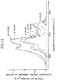
- Figure 10 is a graph showing a time-dependent nature of the growth of native oxide films.
- Figure 11 is a graph showing a dependency of the concentration of adsorbed water on partial pressure of water.
- Figure 12 is a graph showing the time dependent process of adsorption of organic contaminations in a clean room environment.
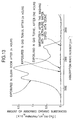
- Figure 13 is a graph showing the time dependent process adsorption of organic contaminations in a controlled gas atmosphere.
- the substrate wafers are transported through a gas tunnel wherein a purge gas flows, from one process chamber to another process chamber in a manufacturing line having a several process chambers providing separate processes to the same group of wafers.
- the gas tunnel is a hermetic structure, preventing an exterior atmosphere from seeping into the tunnel space, and lowering the opportunities for various contaminations to contact the substrate surfaces by excluding the exterior atmosphere.
- the purge gas is a filtered inert gas which has been processed to remove microparticles and moisture, and which does not react with the wafer material, for example, gaseous nitrogen, argon or helium.
- purge gas contains oxygen added to an inert gas, so as to prevent the oxygen deficient environment, should a breakage occur in the gas tunnel.
- the method disclosed in a Japanese Patent Application, Second Publication, S55-38828 is based on channels formed on the tracks for transporting the wafers, and a gas is ejected along the channels to propel the wafers.
- the method disclosed in a Japanese Patent Application, First Publication, H5-211225 is based on a dual passage structure, as shown in Figure 3, formed by a dividing plate 13 to divide the tunnel space into upper and lower passages in which the lower passage 14 below the dividing plate 13 is used to flow a transport gas which floats the substrate wafers 10, and the upper passage 16 above the dividing plate 13 is used for purge gas to keep the wafers free of contaminations.
- the transport gas flows from the lower passage 14, through numerous jet holes 15 in the dividing plate 13, and enters into the upper passage 16, where it floats the wafers 10 and transport them through the upper passage 16.
- the transport device for moving the wafers 10 in the tunnel is not restricted to such a gas-driven system, but other systems based on such methods as belt conveyor, magnetic or ultrasonic means, are suitable.
- a semiconductor laser detection system is utilized in conjunction with the tunnel to measure the concentrations of contaminations and/or oxygen.
- the semiconductor laser detection system comprises at least a laser oscillator which oscillates a laser beam having an output wavelength in the infrared region; and a laser detector to receive the laser beam to determine the absorption spectra of the input laser beam.
- the laser oscillator and the laser detector are not particularly limiting so long as they can, respectively, oscillate and receive a required wave length as described below.
- the one used in the present invention is a variable wavelength laser, and it was found that a distributed feedback (DFB) semiconductor laser in the InGaAsP system is suitable.
- the DFB semiconductor laser has its diffraction grating within the current injection region, and is a single-mode laser oscillator, and therefore, does not require an optical filter such as a monochromator, and the optical power loss is also small, and can be made into a compact unit.
- a Distributed Bragg Reflection (DBR) laser which has its diffraction grating outside the current injection region and is a single-mode laser oscillator is also suitable.
- Suitable laser detectors are those that are sensitive to the output wave length from the laser oscillator, for example, a solid element laser detector based on Ge or InGaAs.
- Such a semiconductor laser detection system it is possible to measure the concentrations of contaminations or oxygen in the tunnel space, by providing a window section which transmits the laser beam at the tunnel and placing the laser oscillator and laser detector appropriately in the window section.
- This arrangement eliminates the need to install the laser detection system in the interior of the tunnel, so that there is no interference with the substrate transport process.
- This semiconductor laser detection system can detect a very small amount of contaminations (0.1 ppm level). Also, the adjustments of output wavelength and optical axis to be carried out are easy.
- a detection technique based on analyzers such as gas chromatography is time consuming for obtaining results, but the present method based on determining the absorption spectra of a semiconductor laser beam enables to produce an instantaneous result of measurements of concentrations of contaminations and/or oxygen. Therefore, semiconductor laser beam system is suitable for use in feedback control of the process.
- an output wavelength region in a range of 1.35-1.42 ⁇ m is suitable.
- an output wavelength should be between 1.43-1.46 ⁇ m for CO 2 , between 1.29-1.50 ⁇ m for CH 4 , between 1.19-2.00 ⁇ m for SiH 4 , between 1.25-1.35 ⁇ m for HF, between 1.34-1.37 ⁇ m for HBr and between 0.75-0.78 ⁇ m for O 2 .
- Quantitative determination of contaminations and/or oxygen using a semiconductor laser is presented in various known art, for example, a Japanese Patent Application, First Publication, H5-99845 can be used.
- the simple technique consist of measuring the absorption spectra and subtracting the absorption spectrum corresponding to the gas spectrum of the inert gas (e.g., nitrogen) inside the tunnel so as to define and identify the peaks corresponding to contaminations and oxygen, and determine their concentrations from the values of the absorption intensity of selected absorption peak where in there is little interfering peak nearby.
- the inert gas e.g., nitrogen
- Scanning wave lengths can be done readily by adjusting the injection current or temperature of the laser oscillator.
- a semiconductor laser arrangement comprising a laser oscillator and scattered beam detector, as shown in Figure 4 is suitable.
- a gas tunnel 12 to transport substrate wafers 10 is provided with a laser oscillator 20a disposed about a window section 73 oscillating a laser beam 17, and the laser beam 17 is detected by a laser detector 20b disposed about a window section 75.
- the laser oscillator 20a and the laser detector 20b are connected to an spectrometer controller (not shown), and the contamination concentrations in the tunnel space is computed from the measured values of the spectral intensity by the spectrometer controller.
- a scattered beam detector 18 is disposed on an axis at right angles to the beam axis of the laser beam 17, and a spherical reflector member 19, comprising mirrors and the like, is disposed across the beam axis, opposite to the scattered beam detector 18.
- the scattered beam detector 18 and the reflector member 19 are also connected to the scattered beam controller (not shown) which computes the number and the particle size of the solid contaminations present in the tunnel space of the gas tunnel 12 from the measured value of the scattered beam intensity.
- the spectrometer controller and the scattered beam controller can be separate units or a shared unit.
- This arrangement enables to determine the concentration of the gaseous contaminations by measuring the absorption spectral intensity of the laser beam with the laser detector 20b while determining the concentration of the solid contaminations by measuring the scattered beam intensity of the laser beam with the scattered beam detector 18.
- the output wavelength range of the laser beam of 0.75-0.78 ⁇ m is suitable for determining the concentration of the solid contaminations from the measurements of the scattered beam intensity, and the same wavelength ranges used in scanning for various gas contaminations, mentioned previously, can be used satisfactorily.
- Figure 5 shows the results obtained by synchronizing the measurement processes for absorption spectra intensity and the scattered beam intensity.
- the horizontal axis represents time in seconds and the vertical axis represents the intensity of absorption spectra or scattered beam in appropriate units.
- the scanning wavelength of the laser beam is fixed at 0.761 ⁇ m, so that the concentrations of oxygen is measured by the absorption spectra intensity and of the solid contaminations by the scattered beam intensity.
- the size of the solid contaminations alters the scattered beam intensity, for a fixed value of laser beam intensity, so that the size can be determined from the measurements of the scattered beam intensity.
- the transport process in order to transport the substrate wafers in a highly clean condition to each process chamber, at all times, the transport process is controlled on the basis of the contamination and oxygen concentration data output from the semiconductor laser detection system.
- An example of the substrate transport method is to control the flow volume of the purge gas flowing in the tunnel space, on the basis of the data obtained from the contamination concentration data in the tunnel space mentioned above.
- the contamination is water
- the moisture level inside the tunnel space at less than 0.1 ppm, the formation of native oxide film on the substrate surface can be prevented.
- the reduction in the moisture level to less than 0.1 ppm can also be done by controlling the flow volume of purge gas.
- the level of contaminations determined in the upper passage 16 is measured to control the flow rate of the purge gas.
- evacuation openings communicating with an exhaust pump on the tunnel so that at least the gases around the evacuation openings can be extracted.
- evacuation openings enable to quickly remove locally generated high concentrations of contaminations by operating a vacuum pump connected to such evacuation openings, should such an even occur inside the tunnel space.
- control modes for transporting substrate wafers inside a gas tunnel, is to provide an alternative route for transportation.
- processing problems develop inside a process chamber caused by contaminations adhering to the wafer surface, for example, it has been necessary to shut down the entire transport system.
- Figure 6 shows an example of such a routing scheme.
- the mainline 46 consists of blocks A1-A2-A3 and A4.
- a subline 48 branching out from the mainline 46, consists of blocks B1-B2-B3-B4-B5-B6-B7-B8 and B9.
- a subline 50 consists of blocks C1-C2-C3 -C4-C5-C6-C7-C8 and C9. From the subline 48, branch lines D1, D2, E1, E2, F1, F2 are provided, and from the subline 50, branch lines D3, D4, E3, E4, F3, F4 are provided.
- Process chamber 34 is connected to the branch lines D1, D2; process chamber 36 to branch lines D3, D4, process chamber 38 to branch lines E1 E2, process chamber 40 to branch lines E3, E4, process chamber 42 to branch lines F1, F2 and process chamber 44 to branch lines F3, F4.
- a semiconductor laser detection system comprising, a laser oscillator 20a in block A2 and a laser detector 20b for receiving laser beams oscillated from a laser oscillator 20a in block B9.
- a laser detection system comprising, a laser oscillator 21a in block A3 and a laser detector 21b to work with a laser oscillator 21a in block C9; a laser detection system comprising a laser oscillator 22a in block D1 and a laser detector 22b to work with a laser oscillator 22a in block D2; a laser detection system comprising a laser oscillator 23a in block D3 and a laser detector 23b to work with a laser oscillator 23a in block D4; a laser detection system comprising a laser oscillator 26a in block E1 and a laser detector 26b to work with a laser oscillator 26a in block E2; a laser detection system comprising a laser oscillator 27a in block E3 and a laser detector 27b
- a laser detection system comprising a laser oscillator 24a in block D1 and a laser detector 24b to work with a laser oscillator 24a in block D3; a laser detection system comprising a laser oscillator 25a in block D2 and a laser detector 25b to work with a laser oscillator 25a in block D4; a laser detection system comprising a laser oscillator 28a in block E1 and a laser detector 28b to work with a laser oscillator 28a in block E3; a laser detection system comprising a laser oscillator 29a in block E2 and a laser detector 29b to work with a laser oscillator 29a in block E4; a laser detection system comprising a laser oscillator 32a in block F1 and a laser detector 32b to work with a laser oscillator 32a in block F3; a laser detection system comprising a laser oscillator 33a in block F2 and a laser detector 33b to work with a laser oscillator 33a in block
- the transport system operates as follows.
- the substrate wafers which have been transported through the mainline 46 may proceed along any one of the following routes to receive an identical processing: A1-A2-B1-B2-D1 -process chamber34-D2-B3-C3-C2-C1-A3-A4; or A1-A2-B1-B2-B3 -B4-B5-E1-process chamber 38-E2-B6-C6-C5-C4-C3-C2-C1-A3-A4; or A1-A2-B1-B2-B3-B4-B5-B6-B7-B8-B9-C9-F4 -process chamber 44-F3-C8-C7-C6-C5-C4-C3-C2-C1-A3-A4.
- the substrate routing was A1-A2-B1-B2-D1-process chamber 34-D2-B3-C3-C2-C1 -A3-A4, when the laser detection system comprising laser oscillator 20a and laser detector 20b or that comprising laser oscillator 22a and laser detector 22b indicated a high contamination readings, the substrate routing may be switched to, for example, A1-A2-A3-C1-C2-C3-D4 -process chamber 36-D3-C2-C1-A3-A4.
- Other examples may include a case of switching the process chambers, such that a planned process chamber 40 may be switched to another process chamber when the laser detection system comprising the laser oscillator 27a and laser detector 27b detects high contaminations.
- the substrate routing should be chosen such that this block B2 is avoided. Accordingly, by placing several units of laser detection system in the transport system, detection of contaminations need not be limited to line configurations but can be carried out in specific local regional configurations.
- the present transport system because local regions of high contaminations can be detected, it is possible to operate continually without either shutting down the transport system or having the work waiting to be processed, by choosing a routing so as to avoid the contaminated regions.
- the system can be made more flexible by having isolation shutters for blocking off each block as the occasion demanded so that by isolating the highly contaminated regions from other clean regions within the tunnel space, intrusion of contaminations into the clean regions can be prevented, thus minimizing any potential damage to the operation and facilitating the resumption of activities.
- the present transport system allows a plurality of units of laser detection system to be distributed suitably in the tunnel space, so that special emphasis can be placed on those regions which are prone to contamination by placing more units in those regions. Also, so long as window sections are pre-installed in the tunnel, the detector units may be moved from one window section to another window section of a problem region.
- mainline 52 and process chamber 56 are communicated with a subline 60 which is provided with a laser detection system comprising a laser oscillator 58a and a laser detector 58b at an end section of the subline 60.
- the transport system in this embodiment is provided with a stockyard 54 for storing many substrate wafers 62, and the stockyard 54 is joined with the mainline 52 in block G1, and the stockyard 54 is joined with the process chamber 56 in block G2.
- the wafers 62 are normally routed through the sequence A1-A2-A3-A4-subline 60 -process chamber 56-subline 60-A4-A5. If the laser detection system having a laser oscillator 58a and laser detector 58b detects high contaminations in subline 60, the wafers 62 are re-routed to A1-A2-G1-stockyard 54, and until the problems in subline 60 are corrected, the wafers 62 are successively forwarded to and stored in the stockyard 54.
- the wafers 62 are transported through block G2 to process chamber 56, from where the wafers 62 which have been processed in process chamber 56 are returned to the mainline 52 from subline 60 to be forwarded to another process chamber.
- control methodology related to the present substrate transport system is to incorporate a cleaning chamber prior to entering one of the process chambers so that, depending on the contamination data inside the tunnel space, appropriate cleaning step can be carried out.
- An example will be presented with reference to Figure 8.
- the system shown in Figure 8 includes a mainline 46 and a subline 48 which is provided with a process chamber 34 to perform film deposition process, for example.
- the operation of such a system is as follows.
- the substrate wafers which have been transported on the mainline 46 enter into subline 48.
- a laser detection system disposed on the mainline 46 is used to measure the contamination level in the tunnel space. If the contamination level is small enough to be neglected, the wafers are allowed enter into the process chamber 34 to be processed, the wafers are directly transported to the process chamber 34 and prescribed process such as a film deposition is carried out at the process chamber 34.
- the processed wafers are transported from subline 48 to mainline 46 to be forwarded to other process chambers.
- the contamination level in the tunnel space is high, and the wafers cannot be processed in their current state, then, contaminated wafers which have been transported into the subline 48 from the mainline 46 are first placed into the cleaning chamber 70. After the wafers have been cleaned with some cleaning process in the cleaning chamber 70, the wafers are allowed to enter into the process chamber 34 to be processed, thence the wafers are transported to other process chambers. Therefore, only those wafers which are contaminated are routed to cleaning chamber 70 before entering into the process chamber 34.
- uncontaminated wafers not requiring cleaning are directly placed into process chamber 34, so only clean wafers are placed into the process chamber 34 to be processed by an appropriate process. Also, uncontaminated substrate wafers are not subjected to the cleaning process thus saving these wafers from receiving unnecessary cleaning and possible damages to the surface.
- Another embodiment of the transport system is to control modes of cleaning depending on the level of contamination in the tunnel space.
- more than one cleaning chamber can be provided so that in addition to providing the appropriate level of cleaning to the wafers, different ability or types of cleaning can be given to the wafers, for example, a cleaning chamber specific to adsorbed water removal, a cleaning chamber specific to native oxide film, or a cleaning chamber specific to organic contaminations so that, depending on the type of contaminations, the wafers may be directed to any appropriate cleaning chamber.
- a partial pressure of water may be selected as an indicator to adjust the conditions in the tunnel space, and in such a case, it is desirable to maintain the partial pressure of water at less than 0.1 Pa. By maintaining the partial pressure to be less than 0.1 Pa, the growth of native oxide film on the substrate surface can be controlled.
- the flow rate of the clean inert gas or oxygen flowing inside the tunnel space is too low, there is a danger of increasing the contamination level inside the tunnel space. Because the level of contaminations, specially moisture, is often caused by moisture leaving the inner walls of the gas tunnel, it is possible to lower the partial pressure of moisture by increasing the flow rate. However, if the flow rate is constantly set at a rate far above the level required to transport the substrate wafers, although the partial pressure of water can be kept low, other problems such as treatment of spent gas and load on the compressor for sending the gas through the system are increased, and undesirable extra costs are apt to be incurred.
- one or both flow rates for the inert gas and oxygen can be suitably controlled to prevent increase in the partial pressure of water, thus preventing adsorption of moisture on the wafers as well as excessive use of inert gas or oxygen so that the system operation becomes cost effective.
- XPS X-ray photoelectron spectroscopy
- Native oxide film is produced under the coexistence of water and oxygen. So, for a given set of tunnel conditions, such as the oxygen level and the temperature of the environment, the presence or absence of native oxide film, for a given type of substrate material, is determined uniquely by the magnitude of the partial pressure of water in the tunnel environment, to which the wafer surface is exposed, as well as by the duration of exposure at that partial pressure. Therefore, by measuring the water partial pressure to which the wafers have been exposed and the travel time in the tunnel space, it is possible to judge whether native oxide film on the wafer surface is present or not.
- the type of substrate material is accurately known on the basis of information from the prior process chambers, and the exposure time and travel time at a water partial pressure in the tunnel space can also accurately be determined by instruments so that not only the possible presence of native oxide film but its thickness can be precisely determined.
- the wafers are cleaned depending on the presence or absence of native oxide film.
- a laser detection system and a pressure gauge are provided in the mainline 46 to measure the water partial pressure in the gas tunnel. If the water partial pressure is sufficiently low to present no problem such that the wafers can be processed directly, the wafers entering into the subline 48 are loaded directly into the process chamber 34 to receive a certain processing therein, and the processed wafers are transported again from the subline 48 to the mainline 46 to be forwarded to other process chambers.
- the wafers When the water partial pressure is somewhat high, the wafers are transported into the cleaning chamber 70, through the subline 48 from the mainline 46, and after the wafers have been cleaned into the cleaning chamber 70, they are processed in the process chamber 34 to be transported to other process chambers.
- the partial pressure if the partial pressure is less than 0.1 Pa, moisture adsorbed on the wafer surface exits as water, therefore, a low-energy cleaning process is used to lightly clean the surface.
- an energy sufficiently high to enable removal of the film is used, and the cleaned wafers are then allowed to enter into the process chamber 34.
- the transport system described above can accurately respond in an appropriate way to the need for cleaning, depending on the thermodynamic state of the adsorbed moisture whether it exists in a form of native oxide film or as simple water molecules.
- the wafers are not treated with unnecessarily harsh cleaning process to cause possible surface damage, so that processing are always applied to damage-free, sufficiently clean surfaces to avoid producing defective substrate.
- a gas tunnel 64 for transporting the substrate wafers 10 is communicated with a transport chamber 66 having a process chamber 67, 68 and 69 and a cleaning chamber 70.
- the gas tunnel 64 has an inert gas entry device 72 which admits an inert gas, such as nitrogen, into the tunnel space 64 through a valve 71.
- the inert gas functions as a purge gas as well as a transport gas for moving the wafers 10.
- the gas tunnel 64 has window section 73 for the laser oscillator 74, and a laser detector 76 to detect a laser beam 79 through a window section 75.
- the laser oscillator 74 and the laser detector 76 are connected to an spectrometer controller 78 to compute the contamination level inside the tunnel space 64 from the absorption spectral intensity measured.
- the gas tunnel 64 is provided with a set of a scattered beam detector 88 and its reflector 89, and another set of scattered beam detector 90 and a reflector 91. They are also connected to the spectrometer controller and compute the concentrations of solid contaminations from the scatted beam intensity measured.
- the transport chamber 66 is communicated with the gas tunnel 64 though a gate valve 80 and with process chambers 67, 68, 69 through a each gate valve 81, and with the cleaning chamber 70 through a gate valve 82.
- three process chambers are provided to carry out different processes, but one or two process chambers or more than four process chambers can also be provided, depending on the need of the system. Similarly, only one cleaning chamber is shown but more than one cleaning chamber can be employed.
- the transport chamber 66 is provided with a wafer distributor 83.
- the wafer distributor 83 is used to deliver or accept substrate wafers 10 between the various sites, such as between gas tunnel 64 and the transport chamber 66, or between the transport chamber 66 and the process chambers 67, 68, 69, or between the transport chamber 66 and the cleaning chamber 70.
- the process chambers 67, 68 and 69 are used to provide a certain processing to the wafers 10, for example, CVD device and evaporation device used in thin film forming processes, diffusion furnace used for doping processes, and plasma etching device used for etching processes.
- the cleaning chamber 70 is for cleaning the surfaces of wafers 10, and includes an ion cleaning device to bombard the surface with argon ions and a plasma cleaning device.
- process step controller 84 The operation of these component devices, such as wafer distributor 83, process chambers 67, 68 and 69 and cleaning chamber 70 is controlled by a process step controller 84.
- transport chamber 66 may be communicated with a line of gas tunnel 64.
- a plurality of transport chambers may be communicated in series.
- the process step controller 84 is connected to the spectrometer controller 78, and the process step controller 84 controls the operation of chambers such as cleaning chamber 70 on the basis of contaminations data output from the spectrometer controller 78.
- the spectrometer controller 78 is also connected to the inert gas entry device 72, which operates on the basis of the contaminations data output from the spectrometer controller 78.
- the pressure inside the gas tunnel 64 is higher than that in the transport chamber 66, therefore, there are provided isolation valves 86 to isolate the wafers 10 in the tunnel space 64, when the wafer distributor 83 is receiving the wafers 10 from the gas tunnel 64 into the transport chamber 66.
- one spectrometer controller 78 may be used to output data to these process step controllers 84, or if preferred, a number of spectrometer controllers 78 may be provided corresponding with each of the process step controllers 84.
- the wafers which have been transported through the tunnel space 64 are stopped in front of the gate valve 80, and the isolation valves 86 isolate the wafers 10 from other wafers 10 in the tunnel space 64, and when the gate valve 80 is opened, the wafers 10 are placed inside the transport chamber 66 by means of the wafer distributor 83.
- the wafer distributor 83 transfers the wafers 10 into the cleaning chamber 70, and the wafers 10 are cleaned therein.
- the contaminations data regarding the environment inside the tunnel space 64 have already been transmitted from the laser detection system to the process step controller 84, and the cleaning chamber 70 cleans the wafer surface based on their data. That is, if the contamination level inside the tunnel space 64 is low, a low-energy cleaning process (e.g., less than 0.2 eV) is used so as not to impact damage to the surface. If the level of solid contaminations inside the tunnel space 64 is high, such that solid particles are suspected to be adhered to the wafer surface, the surface is irradiated with a high density ion while flowing an inert gas at a low temperature, or the surface is cleaned with pure water applied to the surface. If the contamination level appears to be even higher (e.g., higher than 0.1 ppm), cleaning is carried out at a higher energy level (e.g., 0.3-5 eV) sufficient to remove any native oxide film which may have formed on the wafer surface.
- a higher energy level e.g. 0.3-5 eV
- the wafers 10 inside the cleaning chamber 70 are transferred, by means of the wafer distributor 83, into the process chamber 67 to provide a certain processing treatment, such as film deposition, to the wafers 10.
- the transport routing may be switched so that, without going through the cleaning chamber 70, the wafers 10 may be directly loaded into the process chamber 67 by means of the wafer distributor 83.
- the wafers 10 are transferred again from the process chamber 67 and others to the gas tunnel 64 by means of the wafer distributor 83.
- the contaminations data are also supplied to the inert gas entry device 72 so that, if the contamination level is high, the flow rate of inert gas is increased to lower the concentration of the contaminations in the tunnel space 64.
- the combined action of lowering the contaminations level in the tunnel space 64 and cleaning process appropriate to the level of contamination of the surface it is possible to provide an uninterrupted supply of substrate wafers of highly controlled cleanliness to the process chambers.
- nitrogen gas containing about 1 v/o of gaseous HF may be introduced to facilitate removal of the oxide film.
- the substrate surface can be terminated with fluorine molecules, and if this should happen, irradiating the surface with a radiation of wavelength less than 800 nm can desorb the fluorine from the surface.
- the pressures inside the tunnel space 64 and the transport chamber 66 should be the same when the gate valve 80 is made to operate.
- the pressures inside the process chambers 67-69 and the transport chamber 66 be the same when the gate valve 81 is operated.
- the normal pressure inside the gas tunnel is over 760 torr, and the pressures inside the process chambers 67-69 are less than 1 torr.
- a pressure regulator is provided in the transport chamber 66 so that, when the gate valve 80 is to be opened, the pressure inside the transport chamber 66 should be increased (760 torr) to equalize the pressures between the tunnel space 64 and the transport chamber 66, and when the gate valve 81 is to be opened, the pressure inside the transport chamber 66 should be lowered (1 torr) so as to equalize the pressures inside the process chambers 67-69 and the transport chamber 66.
- Regulation of pressures in the transport chamber 66 require a pressure regulating device which can handle a highspeed gas pumping and maintain high cleanliness.
- a suitable device is a two-stage arrangement of an oil-free Turbo Molecular Pump and a dry pump connected directly in series. To exhaust the transport chamber 66 quickly, a high exhaust capacity pump should be chosen.
- the isolation valves 86 are closed to isolate the wafers 10 inside the tunnel space 64. Then, the pressure regulating device is operated to reduce the pressure in the isolation space formed by the isolation valves 86. The pressure in the isolation space is reduce to less than 1 torr so that it is at the same pressure as that in the transport chamber 66.
- the gate valve 80 is opened, and the wafers 10 are transported from the tunnel space 64 into the transport chamber 66, then to the cleaning chamber 70 or to the process chamber 67 to provide a specified processing.
- the wafers 10 are transported from the transport chamber 66 to the tunnel space 64, and after the gate valve 80 is closed, the pressure in the isolation space bounded by the isolation valves 86 is increased, and the isolation valves 86 are opened and the wafers 10 are forwarded to other process chambers.
- This arrangement has an advantage that the isolation space bounded by the isolation valves 86 is smaller than the transport chamber 66, that is, the space for regulating pressure is small, and it can be exhausted at a much faster rate and the processing productivity is increased.
- the isolation valves 86 can be eliminated to make the system more simple.
- the gaseous molecular stream speed is increased, thus enabling a small volume of transport gas to move the substrate wafers and allowing to reduce the flow rate of the transport gas needed for the gas tunnel 64.
- the laser detection system can generate the contamination data as secondary differential signals rather than direct absorption signals by the contamination to provide more sensitive data.
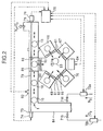
- Embodiment 2 will be presented with reference to Figure 2.
- Embodiment 2 is basically the same as Embodiment 1, except that an inert gas entry device 72a and an oxygen gas entry device 72b are provided for the gas tunnel 64 so that an inert gas, such as nitrogen, and oxygen gas can be admitted into the tunnel space 64 through the valves 71a and 71b.
- a laser oscillator 74 and a laser detector 76 provided in the gas tunnel 64 measure the intensity values of absorption spectra, and the spectrometer controller 78 computes the oxygen concentration inside the tunnel space 64.
- the tunnel space 64 is instrumented with a pressure gauge 92 which is connected to the spectrometer controller 78 to computes a partial pressure of water inside the tunnel space 64.
- the spectrometer controller 78 is connected with the inert gas entry device 72a and the oxygen gas entry device 72b, and both the inert gas entry device 72a and the oxygen gas entry device 72b are controlled by the spectrometer controller 78, and are operated according to the output data from the controller 78 which limits their flow rates so as to keep the partial pressure of water at less than 0.1 Pa.
- the partial pressure data inside the tunnel space 64 are transmitted from the spectrometer controller 78 to the process step controller 84, and the cleaning chamber 70 cleans the surface of the wafers 10 on the basis of the output data. That is, when the partial pressure of water in the tunnel space 64 is less than 0.1 Pa, then cleaning process is carried out at a low-energy level, for example 0.2 eV so as not to impact damage to the wafers. On the other hand, if it is judged that native oxide film has been formed on the surface, an energy level sufficient to remove such films, for example, an energy range 0.3-5 eV is used, or cleaning with dilute hydrofluoric acid and pure water wash is used.
- the contaminations data such as partial pressure of water
- the inert gas entry device 72a and the oxygen gas entry device 72b are supplied to the inert gas entry device 72a and the oxygen gas entry device 72b, so that, when the contamination level is high, the flow rates of inert gas and oxygen are increased to reduce the contaminations level inside the tunnel space 64.
- the cleaning process adapted to the contamination level a highly precise degree of cleanliness can be maintained on the wafer surface, so the processing can be carried out under stable conditions, and also the use of both inert gas and oxygen in the gas tunnel 64 allows reduction in the capital cost and peripheral facilities cost for dealing with the problems associated with oxygen deficient environment.
- Embodiment 3 will be presented with reference to Figure 9.
- Embodiment 3 is essentially the same as Embodiment 1, except that, in addition to the gate valve 80, another gate valve 85 is provided between the gas tunnel 64 and the transport chamber 66, and a moderator chamber 87 is provided between the gate valve 80 and the gate valve 85.
- a pressure regulator device (not shown) is provided so that the pressure inside the chamber may be freely regulated.
- the processed wafers 10 are moved out of the transport chamber 66 and returned to the moderator chamber 87, and after the gate valve 85 has been closed, the pressure inside the moderator chamber 87 is restored to 760 torr. Then, the gate valve 80 is opened, and the wafers 10 inside the moderator chamber 87 are transported to the gas tunnel 64.
- the moderator chamber 87 is smaller than the transport chamber 66, pressure regulating process can be carried out much more quickly and reliably for the moderator chamber 87 than for a similar process for the transport chamber 66, and such a system has an another advantage that the throughput is increased.
- the transport chamber 66 is disposed between the moderator chamber 87 and the process chambers 67-69, possibility of byproducts produced in the process chambers 67-69 to enter as far as the moderator chamber 87 has been minimized.
- the transport chamber 66 is rarefied under a reduced pressure, the microparticles such as dust particles can easily fall to the floor and are effectively prevented from reaching the moderator chamber 87. Therefore, even if pressure regulation by exhausting or admitting inert gas is carried out rapidly, there is little danger of the dust particles to fly about.
- the substrate material was an n-type, (100)-oriented silicon substrate material having a resistivity range of 2-4 ⁇ ⁇ cm.
- the substrate wafers were exposed to a clean room atmosphere containing a partial pressure of water of higher than 10 Pa, and to a gas tunnel atmosphere containing N 2 and O 2 at a partial pressure of water of 0.1 Pa. In each case, the growth of oxide film on the surface of the substrate wafer was studied as a function of the duration of exposure to the environment. The results are reported in Figure 10.
- the substrate materials were prepared as a coating inside a stainless steel pipe of 4.35 mm inside diameter and 4 m in length.
- the materials for the coating were prepared in four forms: precipitated chromium oxide (Cr 2 O 3 ) ; silicon deposited and oxidized to form silicon dioxide (SiO 2 ); electro-polished (EP) surface; and precipitated magnetite (Fe 3 O 4 ).
- argon gas stream containing a desired partial pressure of water is passed through from an entry end of the pipe, and the time span required to begin discharging argon containing some moisture was determined by monitoring the moisture content at the exit end of the pipe.
- the moisture level in the flowing argon gas is low, for a short time span after flowing the gas, all the moisture in the gas is adsorbed onto the test material, and no water was detected in the exiting argon.
- water in the argon gas began to be detected at the exit end of the pipe.
- Anhydrous HF is highly polarized and has a high solubility for water, so that by flowing this through the pipe, it is possible to remove all the adsorbed water from the interior surfaces.
- the electrical conductivity of HF responds to amount of dissolved water, therefore, by measuring the electrical conductivity of the acid solution, it was possible to compute the amount of water adsorbed onto the surface of the test material.
- Tests were conducted to investigate the effects of adsorption of organic substances contained in the surrounding atmosphere to a surface of the substrate wafer.
- Figure 12 shows the results of exposing silicon substrate wafers to a clean room atmosphere, by determining the time variation of the amount of adsorbed organic substances on the substrate wafers by Fourier Transform Infrared Analysis (FT-IR).
- FT-IR Fourier Transform Infrared Analysis
- Silicon substrate wafers which were cleaned of adsorbed organic substances by washing with ultra-pure water doped with ozone were used. Immediately after the washing step (0 hour), no adsorbed substance on the substrate wafers was observed, but with time of exposure in the clean room, it was seen that the quantity of adsorbed substances was increasing.
- Figure 13 compare the clean room exposure results performed above with the results of exposing the wafers, which had been cleaned in the same way, to the tunnel space atmosphere at a partial pressure of water at 0.1 Pa and flowing purge gas of a mixture of nitrogen and oxygen.
- the tunnel environment is controlled by regulating the flow rates of purge gas, according to measured data of organic contaminations in the tunnel space, so as not to allow entry of organic contaminations into the tunnel space.
Landscapes
- Health & Medical Sciences (AREA)
- General Physics & Mathematics (AREA)
- Physics & Mathematics (AREA)
- Epidemiology (AREA)
- Public Health (AREA)
- Engineering & Computer Science (AREA)
- Environmental & Geological Engineering (AREA)
- Atmospheric Sciences (AREA)
- Life Sciences & Earth Sciences (AREA)
- Computer Networks & Wireless Communication (AREA)
- Container, Conveyance, Adherence, Positioning, Of Wafer (AREA)
- Testing Or Measuring Of Semiconductors Or The Like (AREA)
- Cleaning Or Drying Semiconductors (AREA)
- Drying Of Semiconductors (AREA)
Applications Claiming Priority (5)
| Application Number | Priority Date | Filing Date | Title |
|---|---|---|---|
| JP34408995 | 1995-12-28 | ||
| JP344089/95 | 1995-12-28 | ||
| JP15269596 | 1996-06-13 | ||
| JP152695/96 | 1996-06-13 | ||
| PCT/JP1996/003852 WO1997024760A1 (en) | 1995-12-28 | 1996-12-27 | Method and device for transferring thin plate-like substrate |
Publications (4)
| Publication Number | Publication Date |
|---|---|
| EP0809284A1 true EP0809284A1 (de) | 1997-11-26 |
| EP0809284A4 EP0809284A4 (de) | 2001-04-18 |
| EP0809284B1 EP0809284B1 (de) | 2007-01-31 |
| EP0809284B8 EP0809284B8 (de) | 2007-06-13 |
Family
ID=26481536
Family Applications (1)
| Application Number | Title | Priority Date | Filing Date |
|---|---|---|---|
| EP96942663A Expired - Lifetime EP0809284B8 (de) | 1995-12-28 | 1996-12-27 | Verfahren und Anordnung zum Transport von Substratscheiben |
Country Status (7)
| Country | Link |
|---|---|
| US (2) | US5953591A (de) |
| EP (1) | EP0809284B8 (de) |
| JP (1) | JP3137989B2 (de) |
| KR (1) | KR100260957B1 (de) |
| DE (1) | DE69636880T2 (de) |
| TW (1) | TW315492B (de) |
| WO (1) | WO1997024760A1 (de) |
Cited By (6)
| Publication number | Priority date | Publication date | Assignee | Title |
|---|---|---|---|---|
| DE19826949A1 (de) * | 1998-06-17 | 1999-12-23 | Georg Kunkel | Vorrichtung zum Transport von plattenartigen Substraten, beispielsweise von Glasplatten für Flachbildschirme |
| FR2808098A1 (fr) * | 2000-04-20 | 2001-10-26 | Cit Alcatel | Procede et dispositif de conditionnement de l'atmosphere dans une chambre de procedes |
| FR2807951A1 (fr) * | 2000-04-20 | 2001-10-26 | Cit Alcatel | Procede et systeme de pompage des chambres de transfert d'equipement de semi-conducteur |
| WO2003038869A3 (en) * | 2001-08-31 | 2003-11-27 | Asyst Technologies | Universal modular wafer transport system |
| EP1093022A3 (de) * | 1999-10-12 | 2004-05-06 | ASML Netherlands B.V. | Lithographischer Projektionsapparat |
| US7145643B2 (en) | 2003-08-07 | 2006-12-05 | Asml Netherlands B.V. | Interface unit, lithographic projection apparatus comprising such an interface unit and a device manufacturing method |
Families Citing this family (165)
| Publication number | Priority date | Publication date | Assignee | Title |
|---|---|---|---|---|
| JP3901265B2 (ja) * | 1996-11-26 | 2007-04-04 | 大陽日酸株式会社 | 薄板状基体の搬送方法及び搬送装置 |
| EP1030350A4 (de) | 1998-07-08 | 2007-10-31 | Taiyo Nippon Sanso Corp | System und verfahren zur herstellung und zuführung hochreiner trockener luft |
| US6960057B1 (en) * | 1998-09-30 | 2005-11-01 | Brooks Automation, Inc. | Substrate transport apparatus |
| JP2000264438A (ja) * | 1999-03-16 | 2000-09-26 | Ribaaberu:Kk | ウエーハ搬送装置 |
| US6900439B2 (en) * | 2000-02-24 | 2005-05-31 | Tokyo Electron Limited | Gas leakage detection system, gas leakage detection method and semiconductor manufacturing apparatus |
| TW476996B (en) * | 2000-02-28 | 2002-02-21 | Mitsubishi Material Silicon | Semiconductor manufacturing method and semiconductor manufacturing apparatus |
| US7508487B2 (en) * | 2000-06-01 | 2009-03-24 | Asml Netherlands B.V. | Lithographic apparatus, device manufacturing method, and device manufactured thereby |
| US6939816B2 (en) * | 2000-11-10 | 2005-09-06 | Texas Instruments Incorporated | Method to improve the uniformity and reduce the surface roughness of the silicon dielectric interface |
| JP2002309372A (ja) * | 2001-04-13 | 2002-10-23 | Canon Inc | インライン式成膜装置、成膜方法及び液晶素子 |
| JP3437843B2 (ja) * | 2001-07-06 | 2003-08-18 | 沖電気工業株式会社 | 絶縁膜の形成方法及び集積回路の製造方法 |
| DE10319379A1 (de) * | 2003-04-30 | 2004-11-25 | Applied Films Gmbh & Co. Kg | Vorrichtung zum Transportieren eines flachen Substrats in einer Vakuumkammer |
| US7318947B1 (en) | 2004-08-31 | 2008-01-15 | Western Digital (Fremont), Llc | Method and apparatus for controlling magnetostriction in a spin valve sensor |
| US7595967B1 (en) | 2004-09-07 | 2009-09-29 | Western Digital (Fremont), Llp | Method for fabricating a spacer layer for a magnetoresistive element |
| US7444740B1 (en) | 2005-01-31 | 2008-11-04 | Western Digital (Fremont), Llc | Damascene process for fabricating poles in recording heads |
| DE102006033296A1 (de) * | 2006-07-17 | 2008-01-31 | Manz Automation Ag | Anlage zur Strukturierung von Solarmodulen |
| US8015692B1 (en) | 2007-11-07 | 2011-09-13 | Western Digital (Fremont), Llc | Method for providing a perpendicular magnetic recording (PMR) head |
| WO2010135321A2 (en) * | 2009-05-19 | 2010-11-25 | Applied Materials, Inc. | Method and apparatus for solar cell production line control and process analysis |
| US20110000231A1 (en) * | 2009-07-01 | 2011-01-06 | Mccormick Stephen A | Method and apparatus for ultrasonic freezing |
| US9324576B2 (en) | 2010-05-27 | 2016-04-26 | Applied Materials, Inc. | Selective etch for silicon films |
| CN103250230B (zh) * | 2010-12-13 | 2016-08-31 | Tp太阳能公司 | 掺杂剂涂布系统以及涂布蒸气化掺杂化合物于光伏太阳能晶圆的方法 |
| US10283321B2 (en) | 2011-01-18 | 2019-05-07 | Applied Materials, Inc. | Semiconductor processing system and methods using capacitively coupled plasma |
| US8999856B2 (en) | 2011-03-14 | 2015-04-07 | Applied Materials, Inc. | Methods for etch of sin films |
| US9064815B2 (en) | 2011-03-14 | 2015-06-23 | Applied Materials, Inc. | Methods for etch of metal and metal-oxide films |
| US8771536B2 (en) | 2011-08-01 | 2014-07-08 | Applied Materials, Inc. | Dry-etch for silicon-and-carbon-containing films |
| US8808563B2 (en) | 2011-10-07 | 2014-08-19 | Applied Materials, Inc. | Selective etch of silicon by way of metastable hydrogen termination |
| DE102012210035A1 (de) * | 2012-06-14 | 2013-05-23 | Carl Zeiss Smt Gmbh | EUV-Lithographieanlage und Verfahren zum Detektieren von Partikeln in einer EUV-Lithographieanlage |
| US9267739B2 (en) | 2012-07-18 | 2016-02-23 | Applied Materials, Inc. | Pedestal with multi-zone temperature control and multiple purge capabilities |
| US9373517B2 (en) | 2012-08-02 | 2016-06-21 | Applied Materials, Inc. | Semiconductor processing with DC assisted RF power for improved control |
| US9034770B2 (en) | 2012-09-17 | 2015-05-19 | Applied Materials, Inc. | Differential silicon oxide etch |
| US9023734B2 (en) | 2012-09-18 | 2015-05-05 | Applied Materials, Inc. | Radical-component oxide etch |
| US9390937B2 (en) | 2012-09-20 | 2016-07-12 | Applied Materials, Inc. | Silicon-carbon-nitride selective etch |
| US9132436B2 (en) | 2012-09-21 | 2015-09-15 | Applied Materials, Inc. | Chemical control features in wafer process equipment |
| US8969212B2 (en) | 2012-11-20 | 2015-03-03 | Applied Materials, Inc. | Dry-etch selectivity |
| US8980763B2 (en) | 2012-11-30 | 2015-03-17 | Applied Materials, Inc. | Dry-etch for selective tungsten removal |
| US9111877B2 (en) | 2012-12-18 | 2015-08-18 | Applied Materials, Inc. | Non-local plasma oxide etch |
| US8921234B2 (en) | 2012-12-21 | 2014-12-30 | Applied Materials, Inc. | Selective titanium nitride etching |
| US10256079B2 (en) | 2013-02-08 | 2019-04-09 | Applied Materials, Inc. | Semiconductor processing systems having multiple plasma configurations |
| US9362130B2 (en) | 2013-03-01 | 2016-06-07 | Applied Materials, Inc. | Enhanced etching processes using remote plasma sources |
| US9040422B2 (en) | 2013-03-05 | 2015-05-26 | Applied Materials, Inc. | Selective titanium nitride removal |
| US10170282B2 (en) | 2013-03-08 | 2019-01-01 | Applied Materials, Inc. | Insulated semiconductor faceplate designs |
| US20140271097A1 (en) | 2013-03-15 | 2014-09-18 | Applied Materials, Inc. | Processing systems and methods for halide scavenging |
| JP6403431B2 (ja) * | 2013-06-28 | 2018-10-10 | 株式会社Kokusai Electric | 基板処理装置、流量監視方法及び半導体装置の製造方法並びに流量監視プログラム |
| US9493879B2 (en) | 2013-07-12 | 2016-11-15 | Applied Materials, Inc. | Selective sputtering for pattern transfer |
| US9773648B2 (en) | 2013-08-30 | 2017-09-26 | Applied Materials, Inc. | Dual discharge modes operation for remote plasma |
| US8956980B1 (en) | 2013-09-16 | 2015-02-17 | Applied Materials, Inc. | Selective etch of silicon nitride |
| US9576809B2 (en) | 2013-11-04 | 2017-02-21 | Applied Materials, Inc. | Etch suppression with germanium |
| US9236265B2 (en) | 2013-11-04 | 2016-01-12 | Applied Materials, Inc. | Silicon germanium processing |
| US9520303B2 (en) | 2013-11-12 | 2016-12-13 | Applied Materials, Inc. | Aluminum selective etch |
| US9245762B2 (en) | 2013-12-02 | 2016-01-26 | Applied Materials, Inc. | Procedure for etch rate consistency |
| US9117855B2 (en) | 2013-12-04 | 2015-08-25 | Applied Materials, Inc. | Polarity control for remote plasma |
| US9263278B2 (en) | 2013-12-17 | 2016-02-16 | Applied Materials, Inc. | Dopant etch selectivity control |
| US9287095B2 (en) | 2013-12-17 | 2016-03-15 | Applied Materials, Inc. | Semiconductor system assemblies and methods of operation |
| US9190293B2 (en) | 2013-12-18 | 2015-11-17 | Applied Materials, Inc. | Even tungsten etch for high aspect ratio trenches |
| US9287134B2 (en) | 2014-01-17 | 2016-03-15 | Applied Materials, Inc. | Titanium oxide etch |
| US9396989B2 (en) | 2014-01-27 | 2016-07-19 | Applied Materials, Inc. | Air gaps between copper lines |
| US9293568B2 (en) | 2014-01-27 | 2016-03-22 | Applied Materials, Inc. | Method of fin patterning |
| US9385028B2 (en) | 2014-02-03 | 2016-07-05 | Applied Materials, Inc. | Air gap process |
| US9499898B2 (en) | 2014-03-03 | 2016-11-22 | Applied Materials, Inc. | Layered thin film heater and method of fabrication |
| US9299575B2 (en) | 2014-03-17 | 2016-03-29 | Applied Materials, Inc. | Gas-phase tungsten etch |
| US9299538B2 (en) | 2014-03-20 | 2016-03-29 | Applied Materials, Inc. | Radial waveguide systems and methods for post-match control of microwaves |
| US9299537B2 (en) | 2014-03-20 | 2016-03-29 | Applied Materials, Inc. | Radial waveguide systems and methods for post-match control of microwaves |
| US9136273B1 (en) | 2014-03-21 | 2015-09-15 | Applied Materials, Inc. | Flash gate air gap |
| US9903020B2 (en) | 2014-03-31 | 2018-02-27 | Applied Materials, Inc. | Generation of compact alumina passivation layers on aluminum plasma equipment components |
| US9269590B2 (en) | 2014-04-07 | 2016-02-23 | Applied Materials, Inc. | Spacer formation |
| US9309598B2 (en) | 2014-05-28 | 2016-04-12 | Applied Materials, Inc. | Oxide and metal removal |
| US9847289B2 (en) | 2014-05-30 | 2017-12-19 | Applied Materials, Inc. | Protective via cap for improved interconnect performance |
| US9378969B2 (en) | 2014-06-19 | 2016-06-28 | Applied Materials, Inc. | Low temperature gas-phase carbon removal |
| US9406523B2 (en) | 2014-06-19 | 2016-08-02 | Applied Materials, Inc. | Highly selective doped oxide removal method |
| US9425058B2 (en) | 2014-07-24 | 2016-08-23 | Applied Materials, Inc. | Simplified litho-etch-litho-etch process |
| US9496167B2 (en) | 2014-07-31 | 2016-11-15 | Applied Materials, Inc. | Integrated bit-line airgap formation and gate stack post clean |
| US9159606B1 (en) | 2014-07-31 | 2015-10-13 | Applied Materials, Inc. | Metal air gap |
| US9378978B2 (en) | 2014-07-31 | 2016-06-28 | Applied Materials, Inc. | Integrated oxide recess and floating gate fin trimming |
| US9165786B1 (en) | 2014-08-05 | 2015-10-20 | Applied Materials, Inc. | Integrated oxide and nitride recess for better channel contact in 3D architectures |
| US9659753B2 (en) | 2014-08-07 | 2017-05-23 | Applied Materials, Inc. | Grooved insulator to reduce leakage current |
| US9553102B2 (en) | 2014-08-19 | 2017-01-24 | Applied Materials, Inc. | Tungsten separation |
| US9355856B2 (en) | 2014-09-12 | 2016-05-31 | Applied Materials, Inc. | V trench dry etch |
| US9478434B2 (en) | 2014-09-24 | 2016-10-25 | Applied Materials, Inc. | Chlorine-based hardmask removal |
| US9368364B2 (en) | 2014-09-24 | 2016-06-14 | Applied Materials, Inc. | Silicon etch process with tunable selectivity to SiO2 and other materials |
| US10332770B2 (en) * | 2014-09-24 | 2019-06-25 | Sandisk Technologies Llc | Wafer transfer system |
| US9613822B2 (en) | 2014-09-25 | 2017-04-04 | Applied Materials, Inc. | Oxide etch selectivity enhancement |
| US9966240B2 (en) | 2014-10-14 | 2018-05-08 | Applied Materials, Inc. | Systems and methods for internal surface conditioning assessment in plasma processing equipment |
| US9355922B2 (en) | 2014-10-14 | 2016-05-31 | Applied Materials, Inc. | Systems and methods for internal surface conditioning in plasma processing equipment |
| US11637002B2 (en) | 2014-11-26 | 2023-04-25 | Applied Materials, Inc. | Methods and systems to enhance process uniformity |
| US9299583B1 (en) | 2014-12-05 | 2016-03-29 | Applied Materials, Inc. | Aluminum oxide selective etch |
| US10224210B2 (en) | 2014-12-09 | 2019-03-05 | Applied Materials, Inc. | Plasma processing system with direct outlet toroidal plasma source |
| US10573496B2 (en) | 2014-12-09 | 2020-02-25 | Applied Materials, Inc. | Direct outlet toroidal plasma source |
| US9502258B2 (en) | 2014-12-23 | 2016-11-22 | Applied Materials, Inc. | Anisotropic gap etch |
| US9343272B1 (en) | 2015-01-08 | 2016-05-17 | Applied Materials, Inc. | Self-aligned process |
| US11257693B2 (en) | 2015-01-09 | 2022-02-22 | Applied Materials, Inc. | Methods and systems to improve pedestal temperature control |
| US9373522B1 (en) | 2015-01-22 | 2016-06-21 | Applied Mateials, Inc. | Titanium nitride removal |
| US9449846B2 (en) | 2015-01-28 | 2016-09-20 | Applied Materials, Inc. | Vertical gate separation |
| US20160225652A1 (en) | 2015-02-03 | 2016-08-04 | Applied Materials, Inc. | Low temperature chuck for plasma processing systems |
| US9728437B2 (en) | 2015-02-03 | 2017-08-08 | Applied Materials, Inc. | High temperature chuck for plasma processing systems |
| US9881805B2 (en) | 2015-03-02 | 2018-01-30 | Applied Materials, Inc. | Silicon selective removal |
| US9691645B2 (en) | 2015-08-06 | 2017-06-27 | Applied Materials, Inc. | Bolted wafer chuck thermal management systems and methods for wafer processing systems |
| US9741593B2 (en) | 2015-08-06 | 2017-08-22 | Applied Materials, Inc. | Thermal management systems and methods for wafer processing systems |
| US9349605B1 (en) | 2015-08-07 | 2016-05-24 | Applied Materials, Inc. | Oxide etch selectivity systems and methods |
| US10504700B2 (en) | 2015-08-27 | 2019-12-10 | Applied Materials, Inc. | Plasma etching systems and methods with secondary plasma injection |
| US10504754B2 (en) | 2016-05-19 | 2019-12-10 | Applied Materials, Inc. | Systems and methods for improved semiconductor etching and component protection |
| US10522371B2 (en) | 2016-05-19 | 2019-12-31 | Applied Materials, Inc. | Systems and methods for improved semiconductor etching and component protection |
| US9865484B1 (en) | 2016-06-29 | 2018-01-09 | Applied Materials, Inc. | Selective etch using material modification and RF pulsing |
| US10629473B2 (en) | 2016-09-09 | 2020-04-21 | Applied Materials, Inc. | Footing removal for nitride spacer |
| US10062575B2 (en) | 2016-09-09 | 2018-08-28 | Applied Materials, Inc. | Poly directional etch by oxidation |
| US9721789B1 (en) | 2016-10-04 | 2017-08-01 | Applied Materials, Inc. | Saving ion-damaged spacers |
| US10062585B2 (en) | 2016-10-04 | 2018-08-28 | Applied Materials, Inc. | Oxygen compatible plasma source |
| US9934942B1 (en) | 2016-10-04 | 2018-04-03 | Applied Materials, Inc. | Chamber with flow-through source |
| US10546729B2 (en) | 2016-10-04 | 2020-01-28 | Applied Materials, Inc. | Dual-channel showerhead with improved profile |
| US10062579B2 (en) | 2016-10-07 | 2018-08-28 | Applied Materials, Inc. | Selective SiN lateral recess |
| US9947549B1 (en) | 2016-10-10 | 2018-04-17 | Applied Materials, Inc. | Cobalt-containing material removal |
| US10163696B2 (en) | 2016-11-11 | 2018-12-25 | Applied Materials, Inc. | Selective cobalt removal for bottom up gapfill |
| US9768034B1 (en) | 2016-11-11 | 2017-09-19 | Applied Materials, Inc. | Removal methods for high aspect ratio structures |
| US10242908B2 (en) | 2016-11-14 | 2019-03-26 | Applied Materials, Inc. | Airgap formation with damage-free copper |
| US10026621B2 (en) | 2016-11-14 | 2018-07-17 | Applied Materials, Inc. | SiN spacer profile patterning |
| US10566206B2 (en) | 2016-12-27 | 2020-02-18 | Applied Materials, Inc. | Systems and methods for anisotropic material breakthrough |
| US10431429B2 (en) | 2017-02-03 | 2019-10-01 | Applied Materials, Inc. | Systems and methods for radial and azimuthal control of plasma uniformity |
| US10403507B2 (en) | 2017-02-03 | 2019-09-03 | Applied Materials, Inc. | Shaped etch profile with oxidation |
| US10043684B1 (en) | 2017-02-06 | 2018-08-07 | Applied Materials, Inc. | Self-limiting atomic thermal etching systems and methods |
| US10319739B2 (en) | 2017-02-08 | 2019-06-11 | Applied Materials, Inc. | Accommodating imperfectly aligned memory holes |
| US10943834B2 (en) | 2017-03-13 | 2021-03-09 | Applied Materials, Inc. | Replacement contact process |
| US10319649B2 (en) | 2017-04-11 | 2019-06-11 | Applied Materials, Inc. | Optical emission spectroscopy (OES) for remote plasma monitoring |
| US11276590B2 (en) | 2017-05-17 | 2022-03-15 | Applied Materials, Inc. | Multi-zone semiconductor substrate supports |
| JP7176860B6 (ja) | 2017-05-17 | 2022-12-16 | アプライド マテリアルズ インコーポレイテッド | 前駆体の流れを改善する半導体処理チャンバ |
| US11276559B2 (en) | 2017-05-17 | 2022-03-15 | Applied Materials, Inc. | Semiconductor processing chamber for multiple precursor flow |
| US10049891B1 (en) | 2017-05-31 | 2018-08-14 | Applied Materials, Inc. | Selective in situ cobalt residue removal |
| US10497579B2 (en) | 2017-05-31 | 2019-12-03 | Applied Materials, Inc. | Water-free etching methods |
| US10920320B2 (en) | 2017-06-16 | 2021-02-16 | Applied Materials, Inc. | Plasma health determination in semiconductor substrate processing reactors |
| US10541246B2 (en) | 2017-06-26 | 2020-01-21 | Applied Materials, Inc. | 3D flash memory cells which discourage cross-cell electrical tunneling |
| JP6804398B2 (ja) * | 2017-06-28 | 2020-12-23 | 株式会社Screenホールディングス | 熱処理装置および熱処理方法 |
| US10727080B2 (en) | 2017-07-07 | 2020-07-28 | Applied Materials, Inc. | Tantalum-containing material removal |
| US10541184B2 (en) | 2017-07-11 | 2020-01-21 | Applied Materials, Inc. | Optical emission spectroscopic techniques for monitoring etching |
| US10354889B2 (en) | 2017-07-17 | 2019-07-16 | Applied Materials, Inc. | Non-halogen etching of silicon-containing materials |
| US10170336B1 (en) | 2017-08-04 | 2019-01-01 | Applied Materials, Inc. | Methods for anisotropic control of selective silicon removal |
| US10043674B1 (en) | 2017-08-04 | 2018-08-07 | Applied Materials, Inc. | Germanium etching systems and methods |
| US10297458B2 (en) | 2017-08-07 | 2019-05-21 | Applied Materials, Inc. | Process window widening using coated parts in plasma etch processes |
| US10283324B1 (en) | 2017-10-24 | 2019-05-07 | Applied Materials, Inc. | Oxygen treatment for nitride etching |
| US10128086B1 (en) | 2017-10-24 | 2018-11-13 | Applied Materials, Inc. | Silicon pretreatment for nitride removal |
| US10256112B1 (en) | 2017-12-08 | 2019-04-09 | Applied Materials, Inc. | Selective tungsten removal |
| US10903054B2 (en) | 2017-12-19 | 2021-01-26 | Applied Materials, Inc. | Multi-zone gas distribution systems and methods |
| US11328909B2 (en) | 2017-12-22 | 2022-05-10 | Applied Materials, Inc. | Chamber conditioning and removal processes |
| US10854426B2 (en) | 2018-01-08 | 2020-12-01 | Applied Materials, Inc. | Metal recess for semiconductor structures |
| US10964512B2 (en) | 2018-02-15 | 2021-03-30 | Applied Materials, Inc. | Semiconductor processing chamber multistage mixing apparatus and methods |
| US10679870B2 (en) | 2018-02-15 | 2020-06-09 | Applied Materials, Inc. | Semiconductor processing chamber multistage mixing apparatus |
| TWI766433B (zh) | 2018-02-28 | 2022-06-01 | 美商應用材料股份有限公司 | 形成氣隙的系統及方法 |
| US10593560B2 (en) | 2018-03-01 | 2020-03-17 | Applied Materials, Inc. | Magnetic induction plasma source for semiconductor processes and equipment |
| US10319600B1 (en) | 2018-03-12 | 2019-06-11 | Applied Materials, Inc. | Thermal silicon etch |
| US10497573B2 (en) | 2018-03-13 | 2019-12-03 | Applied Materials, Inc. | Selective atomic layer etching of semiconductor materials |
| US10573527B2 (en) | 2018-04-06 | 2020-02-25 | Applied Materials, Inc. | Gas-phase selective etching systems and methods |
| US10490406B2 (en) | 2018-04-10 | 2019-11-26 | Appled Materials, Inc. | Systems and methods for material breakthrough |
| US10699879B2 (en) | 2018-04-17 | 2020-06-30 | Applied Materials, Inc. | Two piece electrode assembly with gap for plasma control |
| US10886137B2 (en) | 2018-04-30 | 2021-01-05 | Applied Materials, Inc. | Selective nitride removal |
| TWI840362B (zh) | 2018-06-04 | 2024-05-01 | 荷蘭商Asm Ip私人控股有限公司 | 水氣降低的晶圓處置腔室 |
| US10872778B2 (en) | 2018-07-06 | 2020-12-22 | Applied Materials, Inc. | Systems and methods utilizing solid-phase etchants |
| US10755941B2 (en) | 2018-07-06 | 2020-08-25 | Applied Materials, Inc. | Self-limiting selective etching systems and methods |
| US10672642B2 (en) | 2018-07-24 | 2020-06-02 | Applied Materials, Inc. | Systems and methods for pedestal configuration |
| US10892198B2 (en) | 2018-09-14 | 2021-01-12 | Applied Materials, Inc. | Systems and methods for improved performance in semiconductor processing |
| US11049755B2 (en) | 2018-09-14 | 2021-06-29 | Applied Materials, Inc. | Semiconductor substrate supports with embedded RF shield |
| US11062887B2 (en) | 2018-09-17 | 2021-07-13 | Applied Materials, Inc. | High temperature RF heater pedestals |
| US11417534B2 (en) | 2018-09-21 | 2022-08-16 | Applied Materials, Inc. | Selective material removal |
| US11682560B2 (en) | 2018-10-11 | 2023-06-20 | Applied Materials, Inc. | Systems and methods for hafnium-containing film removal |
| US11121002B2 (en) | 2018-10-24 | 2021-09-14 | Applied Materials, Inc. | Systems and methods for etching metals and metal derivatives |
| US11437242B2 (en) | 2018-11-27 | 2022-09-06 | Applied Materials, Inc. | Selective removal of silicon-containing materials |
| US11721527B2 (en) | 2019-01-07 | 2023-08-08 | Applied Materials, Inc. | Processing chamber mixing systems |
| US10920319B2 (en) | 2019-01-11 | 2021-02-16 | Applied Materials, Inc. | Ceramic showerheads with conductive electrodes |
| WO2025229523A1 (en) * | 2024-04-30 | 2025-11-06 | Brooks Automation (Germany) Gmbh | Method and system for determining a concentration of at least one component of a gas in a container |
| EP4644869A1 (de) * | 2024-04-30 | 2025-11-05 | Brooks Automation (Germany) GmbH | Verfahren und system zur bestimmung einer konzentration von mindestens einer komponente eines gases in einem behälter |
Family Cites Families (13)
| Publication number | Priority date | Publication date | Assignee | Title |
|---|---|---|---|---|
| US4293249A (en) * | 1980-03-03 | 1981-10-06 | Texas Instruments Incorporated | Material handling system and method for manufacturing line |
| FI85426C (fi) * | 1990-08-03 | 1992-04-10 | Vaisala Oy | Anordning och foerfarande foer maetning av halten av en gas. |
| JP3162144B2 (ja) * | 1990-11-16 | 2001-04-25 | 株式会社渡邊商行 | 薄板状基体搬送装置 |
| US5518360A (en) * | 1990-11-16 | 1996-05-21 | Kabushiki-Kaisha Watanabe Shoko | Wafer carrying device and wafer carrying method |
| JP2634693B2 (ja) * | 1990-11-20 | 1997-07-30 | 日立プラント建設株式会社 | ウエハのクリーニングシステム |
| JP3351802B2 (ja) * | 1991-01-01 | 2002-12-03 | 忠弘 大見 | 薄膜形成装置 |
| US5636035A (en) * | 1991-09-30 | 1997-06-03 | The Trustees Of The Stevens Institute Of Technology | Method and apparatus for dual modulation laser spectroscopy |
| JP3059262B2 (ja) * | 1991-10-08 | 2000-07-04 | 日本酸素株式会社 | ガス中の微量水分分析装置 |
| US5378145A (en) * | 1992-07-15 | 1995-01-03 | Tokyo Electron Kabushiki Kaisha | Treatment system and treatment apparatus |
| JP3300861B2 (ja) * | 1992-07-15 | 2002-07-08 | 東京エレクトロン株式会社 | 熱処理システム |
| JP3183066B2 (ja) * | 1994-11-11 | 2001-07-03 | 株式会社日立製作所 | 搬送システム |
| US5656813A (en) * | 1995-04-04 | 1997-08-12 | Gmd Systems, Inc. | Apparatus for imaging gas |
| JP5538828B2 (ja) | 2009-11-11 | 2014-07-02 | ルネサスエレクトロニクス株式会社 | 半導体装置およびその製造方法 |
-
1996
- 1996-12-27 WO PCT/JP1996/003852 patent/WO1997024760A1/ja not_active Ceased
- 1996-12-27 JP JP09524199A patent/JP3137989B2/ja not_active Expired - Fee Related
- 1996-12-27 EP EP96942663A patent/EP0809284B8/de not_active Expired - Lifetime
- 1996-12-27 DE DE69636880T patent/DE69636880T2/de not_active Expired - Fee Related
- 1996-12-27 KR KR1019970705804A patent/KR100260957B1/ko not_active Expired - Fee Related
- 1996-12-27 US US08/894,497 patent/US5953591A/en not_active Expired - Fee Related
- 1996-12-31 TW TW085116209A patent/TW315492B/zh active
-
1999
- 1999-07-29 US US09/363,875 patent/US6240610B1/en not_active Expired - Fee Related
Cited By (9)
| Publication number | Priority date | Publication date | Assignee | Title |
|---|---|---|---|---|
| DE19826949A1 (de) * | 1998-06-17 | 1999-12-23 | Georg Kunkel | Vorrichtung zum Transport von plattenartigen Substraten, beispielsweise von Glasplatten für Flachbildschirme |
| EP1093022A3 (de) * | 1999-10-12 | 2004-05-06 | ASML Netherlands B.V. | Lithographischer Projektionsapparat |
| FR2808098A1 (fr) * | 2000-04-20 | 2001-10-26 | Cit Alcatel | Procede et dispositif de conditionnement de l'atmosphere dans une chambre de procedes |
| FR2807951A1 (fr) * | 2000-04-20 | 2001-10-26 | Cit Alcatel | Procede et systeme de pompage des chambres de transfert d'equipement de semi-conducteur |
| WO2001082019A1 (fr) * | 2000-04-20 | 2001-11-01 | Alcatel | Procede et dispositif de conditionnement de l'atmosphere dans une chambre de procedes |
| WO2001081651A1 (fr) * | 2000-04-20 | 2001-11-01 | Alcatel | Procede et systeme de pompage des chambres de transfert d'equipement de semi-conducteur |
| US6649019B2 (en) | 2000-04-20 | 2003-11-18 | Alcatel | Apparatus for conditioning the atmosphere in a vacuum chamber |
| WO2003038869A3 (en) * | 2001-08-31 | 2003-11-27 | Asyst Technologies | Universal modular wafer transport system |
| US7145643B2 (en) | 2003-08-07 | 2006-12-05 | Asml Netherlands B.V. | Interface unit, lithographic projection apparatus comprising such an interface unit and a device manufacturing method |
Also Published As
| Publication number | Publication date |
|---|---|
| US5953591A (en) | 1999-09-14 |
| DE69636880T2 (de) | 2007-11-15 |
| DE69636880D1 (de) | 2007-03-22 |
| EP0809284A4 (de) | 2001-04-18 |
| KR19980702405A (ko) | 1998-07-15 |
| US6240610B1 (en) | 2001-06-05 |
| KR100260957B1 (ko) | 2000-07-01 |
| EP0809284B8 (de) | 2007-06-13 |
| TW315492B (de) | 1997-09-11 |
| JP3137989B2 (ja) | 2001-02-26 |
| EP0809284B1 (de) | 2007-01-31 |
| WO1997024760A1 (en) | 1997-07-10 |
Similar Documents
| Publication | Publication Date | Title |
|---|---|---|
| EP0809284B1 (de) | Verfahren und Anordnung zum Transport von Substratscheiben | |
| JP3901265B2 (ja) | 薄板状基体の搬送方法及び搬送装置 | |
| JPWO1997024760A1 (ja) | 薄板状基体の搬送方法および搬送装置 | |
| TWI672077B (zh) | 評估電漿製程裝置中內部表面調節的系統與方法 | |
| KR100445945B1 (ko) | Cvd 장치의 퍼지 방법 | |
| US7159599B2 (en) | Method and apparatus for processing a wafer | |
| US8283644B2 (en) | Measuring in-situ UV intensity in UV cure tool | |
| US20020083409A1 (en) | Process and device for in-situ decontamination of a EUV lithography device | |
| US20160240402A1 (en) | Systems and methods for internal surface conditioning in plasma processing equipment | |
| US6146135A (en) | Oxide film forming method | |
| US20070093071A1 (en) | Method and apparatus for processing a wafer | |
| GB2331107A (en) | Method of optimizing the recipe of a cleaning process for a process chamber for chemical vapour deposition | |
| JP2007186757A (ja) | 真空処理装置及び真空処理方法 | |
| JPH1031039A (ja) | 計測装置および計測方法 | |
| TWI842930B (zh) | 用於使用光學發射光譜來進行偵測的方法 | |
| US20040099282A1 (en) | System and a method for cleaning process chambers and vacuum lines | |
| JPH08209350A (ja) | 薄膜形成装置及び薄膜形成装置のクリーニング方法 | |
| US20080233754A1 (en) | Substrate peripheral film-removing apparatus and substrate peripheral film-removing method | |
| US20250180979A1 (en) | Mask repair apparatus and methods | |
| Barna et al. | MMST manufacturing technology-hardware, sensors, and processes | |
| JPH11176761A (ja) | 炉芯管の洗浄方法およびその機構 | |
| Graf et al. | Characterization and minimization of moisture concentration in atmospheric pressure RTP tools, using an in situ absorption spectroscopy sensor | |
| US20030172953A1 (en) | Method of treating inner wall of apparatus | |
| JPS59181538A (ja) | ドライエツチング装置 |
Legal Events
| Date | Code | Title | Description |
|---|---|---|---|
| PUAI | Public reference made under article 153(3) epc to a published international application that has entered the european phase |
Free format text: ORIGINAL CODE: 0009012 |
|
| 17P | Request for examination filed |
Effective date: 19970731 |
|
| AK | Designated contracting states |
Kind code of ref document: A1 Designated state(s): DE FR GB |
|
| A4 | Supplementary search report drawn up and despatched |
Effective date: 20010301 |
|
| AK | Designated contracting states |
Kind code of ref document: A4 Designated state(s): DE FR GB |
|
| RIC1 | Information provided on ipc code assigned before grant |
Free format text: 7H 01L 21/68 A, 7H 01L 21/00 B |
|
| RAP1 | Party data changed (applicant data changed or rights of an application transferred) |
Owner name: TAIYO NIPPON SANSO CORPORATION |
|
| RTI1 | Title (correction) |
Free format text: METHOD AND SYSTEM FOR TRANSPORTING SUBSTRATE WAFERS |
|
| GRAP | Despatch of communication of intention to grant a patent |
Free format text: ORIGINAL CODE: EPIDOSNIGR1 |
|
| GRAS | Grant fee paid |
Free format text: ORIGINAL CODE: EPIDOSNIGR3 |
|
| GRAA | (expected) grant |
Free format text: ORIGINAL CODE: 0009210 |
|
| AK | Designated contracting states |
Kind code of ref document: B1 Designated state(s): DE FR GB |
|
| REG | Reference to a national code |
Ref country code: GB Ref legal event code: FG4D |
|
| REF | Corresponds to: |
Ref document number: 69636880 Country of ref document: DE Date of ref document: 20070322 Kind code of ref document: P |
|
| RAP2 | Party data changed (patent owner data changed or rights of a patent transferred) |
Owner name: OHMI, TADAHIRO Owner name: TODA, MASAYUKI Owner name: TAIYO NIPPON SANSO CORPORATION |
|
| ET | Fr: translation filed | ||
| PLBE | No opposition filed within time limit |
Free format text: ORIGINAL CODE: 0009261 |
|
| STAA | Information on the status of an ep patent application or granted ep patent |
Free format text: STATUS: NO OPPOSITION FILED WITHIN TIME LIMIT |
|
| 26N | No opposition filed |
Effective date: 20071101 |
|
| PGFP | Annual fee paid to national office [announced via postgrant information from national office to epo] |
Ref country code: FR Payment date: 20081105 Year of fee payment: 13 |
|
| PGFP | Annual fee paid to national office [announced via postgrant information from national office to epo] |
Ref country code: DE Payment date: 20081104 Year of fee payment: 13 |
|
| PGFP | Annual fee paid to national office [announced via postgrant information from national office to epo] |
Ref country code: GB Payment date: 20081106 Year of fee payment: 13 |
|
| GBPC | Gb: european patent ceased through non-payment of renewal fee |
Effective date: 20091227 |
|
| REG | Reference to a national code |
Ref country code: FR Ref legal event code: ST Effective date: 20100831 |
|
| PG25 | Lapsed in a contracting state [announced via postgrant information from national office to epo] |
Ref country code: FR Free format text: LAPSE BECAUSE OF NON-PAYMENT OF DUE FEES Effective date: 20091231 |
|
| PG25 | Lapsed in a contracting state [announced via postgrant information from national office to epo] |
Ref country code: DE Free format text: LAPSE BECAUSE OF NON-PAYMENT OF DUE FEES Effective date: 20100701 |
|
| PG25 | Lapsed in a contracting state [announced via postgrant information from national office to epo] |
Ref country code: GB Free format text: LAPSE BECAUSE OF NON-PAYMENT OF DUE FEES Effective date: 20091227 |