EP0809334A2 - Slip ring assembly - Google Patents
Slip ring assembly Download PDFInfo
- Publication number
- EP0809334A2 EP0809334A2 EP97201526A EP97201526A EP0809334A2 EP 0809334 A2 EP0809334 A2 EP 0809334A2 EP 97201526 A EP97201526 A EP 97201526A EP 97201526 A EP97201526 A EP 97201526A EP 0809334 A2 EP0809334 A2 EP 0809334A2
- Authority
- EP
- European Patent Office
- Prior art keywords
- slip ring
- ring assembly
- assembly according
- slip
- rings
- Prior art date
- Legal status (The legal status is an assumption and is not a legal conclusion. Google has not performed a legal analysis and makes no representation as to the accuracy of the status listed.)
- Withdrawn
Links
Images

Classifications
-
- H—ELECTRICITY
- H01—ELECTRIC ELEMENTS
- H01R—ELECTRICALLY-CONDUCTIVE CONNECTIONS; STRUCTURAL ASSOCIATIONS OF A PLURALITY OF MUTUALLY-INSULATED ELECTRICAL CONNECTING ELEMENTS; COUPLING DEVICES; CURRENT COLLECTORS
- H01R39/00—Rotary current collectors, distributors or interrupters
- H01R39/02—Details for dynamo electric machines
- H01R39/08—Slip-rings
Definitions
- the present invention relates to a slip ring assembly, comprising at least one rotor made of an insulating material, with an at least substantially radial symmetry around a rotation axis, on the outer periphery of which a number of metal slip rings are coaxially placed around the rotation axis, and at least one stator, provided with a number of current collectors each of which makes contact in the operating condition with one slip ring.
- Slip ring assemblies of this type are known from, for instance, US-A-5,224,138 and are frequently employed in engineering, particularly in an arrangement where, for the benefit of a rotating part of the arrangement, signals or supply voltages must be fed in or out.
- a drawback of known slip ring assemblies is formed by the limited breakdown voltage between the adjacent slip rings.
- the breakdown voltage is further adversely affected by metal grit as a result of wear of the current collectors and of the slip rings, the metal grit being liable to be deposited on the insulating material.
- moisture may often penetrate into the slip ring assembly, likewise adversely affecting the breakdown voltage.
- the slip ring assembly according to the invention eliminates this drawback to a significant extent, among other things by enlarging the creepage path without significantly increasing the dimensions, and is characterised in that he rotor is provided with a number of radially extending grooves and that each slip ring is embedded completely countersunk in one of the grooves.
- the grooves are chosen so as to be at least substantially V-shaped in cross-section, which has been found to effect an increase of the breakdown voltage. Surprisingly, it is advantageous in this case to extend the V-shaped grooves into the slip rings.
- An advantageous choice in this context is an embodiment where the V-shaped groove extends for 20%-40% of its total depth into the slip ring.
- the grooves may in this case have a flat or a rounded bottom, which has the advantage that the thickness of the slip rings can be designed relatively thin.
- each V-shaped groove there is necessarily a radially extending transition from the insulating material to the metal of the slip ring.
- this transition plays an important part in the initiation of a breakdown between adjacent slip rings.
- Another advantageous embodiment of the slip ring assembly according to the invention reduces this risk of a breakdown and is characterised in that the transition plane from insulating material to metal is at least substantially perpendicular to the surface of the groove.
- the top angle of the V-shaped groove may be varied whereby the transition plane and the surface of the groove are kept mutually perpendicular, by providing the slip ring in a radial sense with a suitable tapering.
- Yet another embodiment of the slip ring assembly featuring a favourable breakdown voltage is then characterised in that the top angle of the V-shaped groove is 60-90 degrees.
- a problem with slip rings that is also well-known in the art concerns the wear caused by friction between the slip rings and the current collectors.
- Yet another embodiment of the slip ring assembly according to the invention is characterised in that the V-shaped groove is gold-plated for as far as it extends into the slip ring.
- the current collectors preferably comprise a number of gold-plated rods, made of an elastic metal and fitted together on one end in a bundle. Owing to the favourable V-shape of the groove and its flat or rounded bottom the current collector is automatically centred.
- the bundle is automatically held together and lies stable in the groove, which is conducive to a reliable and low-noise contact transition between the slip ring and the current collector. It was found incidentally that bundles of three or seven rods showed very favourable results because they rest particularly stable in the grooves.
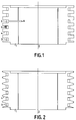
- Fig. 1 shows in cross-section a possible embodiment of a slip ring assembly according to the invention, where a tubular rotor 1, which can rotate around a rotation axis 2 and which is made of an insulating material, for instance epoxy resin, is provided with slip rings 3 which have been fitted countersunk in the insulating material and which are accessible via radially extending grooves 4 formed in the outer periphery of the tubular rotor 1. Also shown is a current collector 5, in this case comprising three elastic metal rods which rest at least substantially tangentially against the associated slip ring, thus providing a connection between the usually rotating slip ring and the non-rotating environment.
- a current collector 5 in this case comprising three elastic metal rods which rest at least substantially tangentially against the associated slip ring, thus providing a connection between the usually rotating slip ring and the non-rotating environment.
- slip rings can be located in axial sense closely adjacent to one another, while nevertheless the creepage path between neighbouring slip rings, and consequently the breakdown voltage between the slip rings, is large. It is further indicated how a connection can be made to a slip ring 3, by providing slip ring 3 with a metal rod 6 which extends into the hollow ring. Of course rod 6 may also take the form of a filament. It is also possible to establish a connection afterwards, by drilling through the ring at the spot where rod 6 is to be positioned, fitting the bore with an internal thread, and screwing home in it a rod 6 provided with an external thread, such that it makes contact with slip ring 3.
- Fig. 2 shows in cross-section an advantageous embodiment of a slip ring assembly according to the invention, where the radially extending grooves have been chosen to be V-shaped in cross-section.
- the further advantage of grooves formed in this manner is that, when the stator is mounted, the current collectors are automatically guided by them to the slip rings 3, hardly ever getting caught behind the raised edges between the grooves.
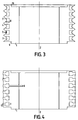
- Fig. 3 shows in cross-section a very advantageous embodiment of the slip ring assembly according to the invention, with the V-shaped groove 4 extending into slip ring 3.
- the current collectors rest confined in a V-shaped groove during operation, which contributes to a sound, stable contact transition.
- the V-shaped groove preferably has a flat bottom, securing for current collectors 5 an especially stable position.
- This embodiment has moreover been found to achieve a still more favourable breakdown voltage, especially if the transitions 7 from insulating material to metal are at least substantially perpendicular to the groove surfaces.
- slip rings as well as the current collectors, to be gold-plated, at least in those places where the actual contact is made. This results in a low contact resistance, little wear and a minimum of noise added by the slip ring assembly to the signals it is required to transport.
- the slip ring assembly according the invention is very suitable as a building element for the assembly of a more complicated assembly.
- rotor 1 is provided with a raised collar 9 on one end and on the other end with a recess 10 that is complementary to the former, or with comparable centring means. Any assembly can then be assembled using this type of building elements.
- Even more universal assembly is possible using, for instance, two types of slip ring assemblies, a first type having, for instance, 6 high-power rings, such as shown in Fig. 1-3, and a second type with 12 more finely machined low-power rings.
- Fig. 4 shows how a slip ring assembly according to Fig. 3 can be realised advantageously.
- the slip rings 3 in this case are introduced into a casting mould, the clearance and the centring of the slip rings being obtained with the aid of the edges 11.
- Next rotor 1 is cast from epoxy resin, preferably in a vacuum centrifugal casting process that is well-known in the art. Subsequently the rotor is provided, for instance on a lathe, with the V-shaped grooves. Finally the slip rings are electro-gold-plated, with the connections 6 available for hook-up to, for instance, a current source.
- Fig. 5 shows in cross-section and in side-view a current collector with three rods 12 which are on one end conductively fitted, for instance soldered, in a metal cylinder 13.
- the current collector is suitable for working in conjunction with a slip ring having a width of 0.65-0.85 mm; the rods have a thickness of 0.15-0.45 mm and are gold-plated. They are made of an elastic material, such that the current collector can be pressed tangentially against a slip ring with a pressure of 1-5 grams without bending more than some ten degrees. Mounted in this manner the current collector is able to transmit 5 amperes over a prolonged period of time. Larger current strengths are possible by fitting several current collectors connected in parallel and distributed over the periphery of the slip ring.
- Fig. 6 shows in cross-section and in side-view a current collector comprising seven rods 12, which is built up in a comparable fashion and which can handle the sustained transmission of 15 amperes.
- the current collector is suitable for working in conjunction with a slip ring having a width of 1.3-1.7 mm; the rods have a thickness of 0.15-0.45 mm.
- the current collectors can be set into blocks of an insulating material, always allowing a number of current collectors to be built together according to Fig. 5 or Fig. 6, such that they can cooperate with the modularly built up slip ring segments.
- a complex slip ring assembly can be assembled from slip ring segments and with current collector segments.
- Fig. 7. shows in cross-section a slip ring assembly of the pancake type according to the invention, as applied if in an axial sense there is little space but in a radial sense there is ample space.
- rotor 1 which is made of insulating material, can rotate around rotation axis 2, but now it has the form of a flat disk, the slip rings 3 being fitted countersunk in the insulating material and accessible via V-shaped grooves 4.
- the grooves and the slip rings are shown only on the upper surface of rotor 1, but it is quite possible to equip the bottom surface with them, too.
- Fig. 8 shows a current collector embodying three rods for application in combination with the pancake. To achieve a well-defined contact the current collector is provided with a curved profile, the curved profile being placed in the groove. Apart from the curved profile the current collector is identical to the current collector described with reference to by Fig. 5.
Landscapes
- Motor Or Generator Current Collectors (AREA)
- Current-Collector Devices For Electrically Propelled Vehicles (AREA)
Abstract
The invention relates to a slip ring assembly featuring a high breakdown voltage between adjacent slip rings (3). To achieve this the rotor (1) is provided with radially extending, cross-sectionally V-shaped grooves (4), the slip rings being positioned at the bottom of the V-shaped grooves. The V-shaped grooves preferably extend into the slip rings, such that also the current collectors (5) rest in a groove.
Description
- The present invention relates to a slip ring assembly, comprising at least one rotor made of an insulating material, with an at least substantially radial symmetry around a rotation axis, on the outer periphery of which a number of metal slip rings are coaxially placed around the rotation axis, and at least one stator, provided with a number of current collectors each of which makes contact in the operating condition with one slip ring.
- Slip ring assemblies of this type are known from, for instance, US-A-5,224,138 and are frequently employed in engineering, particularly in an arrangement where, for the benefit of a rotating part of the arrangement, signals or supply voltages must be fed in or out.
- A drawback of known slip ring assemblies, especially if their construction is compact and the clearance between adjacent slip ring is small, is formed by the limited breakdown voltage between the adjacent slip rings. The breakdown voltage is further adversely affected by metal grit as a result of wear of the current collectors and of the slip rings, the metal grit being liable to be deposited on the insulating material. Besides, moisture may often penetrate into the slip ring assembly, likewise adversely affecting the breakdown voltage.
- The slip ring assembly according to the invention eliminates this drawback to a significant extent, among other things by enlarging the creepage path without significantly increasing the dimensions, and is characterised in that he rotor is provided with a number of radially extending grooves and that each slip ring is embedded completely countersunk in one of the grooves.
- In an advantageous embodiment the grooves are chosen so as to be at least substantially V-shaped in cross-section, which has been found to effect an increase of the breakdown voltage. Surprisingly, it is advantageous in this case to extend the V-shaped grooves into the slip rings. An advantageous choice in this context is an embodiment where the V-shaped groove extends for 20%-40% of its total depth into the slip ring. The grooves may in this case have a flat or a rounded bottom, which has the advantage that the thickness of the slip rings can be designed relatively thin.
- In each V-shaped groove there is necessarily a radially extending transition from the insulating material to the metal of the slip ring. Experiments have shown that this transition plays an important part in the initiation of a breakdown between adjacent slip rings. Another advantageous embodiment of the slip ring assembly according to the invention reduces this risk of a breakdown and is characterised in that the transition plane from insulating material to metal is at least substantially perpendicular to the surface of the groove.
- Besides, in an attempt to raise the breakdown voltage still further, the top angle of the V-shaped groove may be varied whereby the transition plane and the surface of the groove are kept mutually perpendicular, by providing the slip ring in a radial sense with a suitable tapering. Yet another embodiment of the slip ring assembly featuring a favourable breakdown voltage is then characterised in that the top angle of the V-shaped groove is 60-90 degrees.
- A problem with slip rings that is also well-known in the art concerns the wear caused by friction between the slip rings and the current collectors. Yet another embodiment of the slip ring assembly according to the invention is characterised in that the V-shaped groove is gold-plated for as far as it extends into the slip ring. In that case the current collectors preferably comprise a number of gold-plated rods, made of an elastic metal and fitted together on one end in a bundle. Owing to the favourable V-shape of the groove and its flat or rounded bottom the current collector is automatically centred. By advantageously choosing the diameter of the bundle with reference to the dimensions of the groove it can be further accomplished that the bundle is automatically held together and lies stable in the groove, which is conducive to a reliable and low-noise contact transition between the slip ring and the current collector. It was found incidentally that bundles of three or seven rods showed very favourable results because they rest particularly stable in the grooves.
- Experience has shown that the gold on the slip rings and on the current collectors tends to migrate in the operating condition, but a thin layer of gold, effectively serving as a low-impedance lubricant, remains intact. Experiments have demonstrated that, even after a prolonged period of time, the contact transition is still satisfactory if the slip rings are plated with gold that is softer than the gold-plating of the current collectors. The best results are obtained with rods which are cylindrical in cross-section. Very favourable noise characteristics, together with little wear, are achieved by employing three rods per current collector in combination with a narrow slip ring for transmitting small currents, or seven rods in combination with a wide slip ring for larger currents, the contact pressure per current collector then being 1-5 grams and a current collector resting as a close fit in the V-shaped flat-bottomed groove, in the sense that it fills the groove.
- The invention will now be explained in detail with reference to the following figures, where
- Fig. 1
- is a cross-section of a possible embodiment of a slip ring assembly according to the invention;
- Fig. 2
- is a cross-section of an advantageous embodiment of a slip ring assembly according to the invention;
- Fig. 3
- is a cross-section of a very advantageous embodiment of a slip ring assembly according to the invention;
- Fig. 4
- is a cross-section of a slip ring assembly according to the invention prior to the grooves being formed;
- Fig. 5
- is a cross-section and a side-view of a current collector embodying three rods;
- Fig. 6
- is a cross-section and a side-view of a current collector embodying seven rods;
- Fig. 7
- is a cross-section of a slip ring assembly of the pancake type according to the invention;
- Fig. 8
- is a current collector embodying three rods for the pancake.
- Fig. 1 shows in cross-section a possible embodiment of a slip ring assembly according to the invention, where a tubular rotor 1, which can rotate around a
rotation axis 2 and which is made of an insulating material, for instance epoxy resin, is provided withslip rings 3 which have been fitted countersunk in the insulating material and which are accessible via radially extending grooves 4 formed in the outer periphery of the tubular rotor 1. Also shown is acurrent collector 5, in this case comprising three elastic metal rods which rest at least substantially tangentially against the associated slip ring, thus providing a connection between the usually rotating slip ring and the non-rotating environment. The advantage of the slip ring assembly according to the invention is that the slip rings can be located in axial sense closely adjacent to one another, while nevertheless the creepage path between neighbouring slip rings, and consequently the breakdown voltage between the slip rings, is large. It is further indicated how a connection can be made to aslip ring 3, by providingslip ring 3 with ametal rod 6 which extends into the hollow ring. Of courserod 6 may also take the form of a filament. It is also possible to establish a connection afterwards, by drilling through the ring at the spot whererod 6 is to be positioned, fitting the bore with an internal thread, and screwing home in it arod 6 provided with an external thread, such that it makes contact withslip ring 3. - Fig. 2 shows in cross-section an advantageous embodiment of a slip ring assembly according to the invention, where the radially extending grooves have been chosen to be V-shaped in cross-section. Besides a higher breakdown voltage than the embodiment shown in Fig. 1 the further advantage of grooves formed in this manner is that, when the stator is mounted, the current collectors are automatically guided by them to the
slip rings 3, hardly ever getting caught behind the raised edges between the grooves. - Fig. 3 shows in cross-section a very advantageous embodiment of the slip ring assembly according to the invention, with the V-shaped groove 4 extending into
slip ring 3. Besides the advantages mentioned with reference to Fig. 2 a further favourable aspect is that here the current collectors rest confined in a V-shaped groove during operation, which contributes to a sound, stable contact transition. As indicated in Fig. 3 the V-shaped groove preferably has a flat bottom, securing forcurrent collectors 5 an especially stable position. This embodiment has moreover been found to achieve a still more favourable breakdown voltage, especially if the transitions 7 from insulating material to metal are at least substantially perpendicular to the groove surfaces. It has been demonstrated experimentally that the best results are obtained for a top angle of the V-shaped groove of 60-90 degrees, with the slip rings needing to be provided, in a radial sense, with a tapering 8, such that the transitions 7 are perpendicular to the groove surface. - It is further advantageous for the slip rings, as well as the current collectors, to be gold-plated, at least in those places where the actual contact is made. This results in a low contact resistance, little wear and a minimum of noise added by the slip ring assembly to the signals it is required to transport.
- The slip ring assembly according the invention is very suitable as a building element for the assembly of a more complicated assembly. To that end rotor 1 is provided with a raised
collar 9 on one end and on the other end with arecess 10 that is complementary to the former, or with comparable centring means. Any assembly can then be assembled using this type of building elements. Even more universal assembly is possible using, for instance, two types of slip ring assemblies, a first type having, for instance, 6 high-power rings, such as shown in Fig. 1-3, and a second type with 12 more finely machined low-power rings. - Fig. 4 shows how a slip ring assembly according to Fig. 3 can be realised advantageously. The
slip rings 3 in this case are introduced into a casting mould, the clearance and the centring of the slip rings being obtained with the aid of the edges 11. Next rotor 1 is cast from epoxy resin, preferably in a vacuum centrifugal casting process that is well-known in the art. Subsequently the rotor is provided, for instance on a lathe, with the V-shaped grooves. Finally the slip rings are electro-gold-plated, with theconnections 6 available for hook-up to, for instance, a current source. - Fig. 5 shows in cross-section and in side-view a current collector with three rods 12 which are on one end conductively fitted, for instance soldered, in a metal cylinder 13. The current collector is suitable for working in conjunction with a slip ring having a width of 0.65-0.85 mm; the rods have a thickness of 0.15-0.45 mm and are gold-plated. They are made of an elastic material, such that the current collector can be pressed tangentially against a slip ring with a pressure of 1-5 grams without bending more than some ten degrees. Mounted in this manner the current collector is able to transmit 5 amperes over a prolonged period of time. Larger current strengths are possible by fitting several current collectors connected in parallel and distributed over the periphery of the slip ring.
- Fig. 6 shows in cross-section and in side-view a current collector comprising seven rods 12, which is built up in a comparable fashion and which can handle the sustained transmission of 15 amperes. The current collector is suitable for working in conjunction with a slip ring having a width of 1.3-1.7 mm; the rods have a thickness of 0.15-0.45 mm.
- The current collectors can be set into blocks of an insulating material, always allowing a number of current collectors to be built together according to Fig. 5 or Fig. 6, such that they can cooperate with the modularly built up slip ring segments. Thus a complex slip ring assembly can be assembled from slip ring segments and with current collector segments.
- Fig. 7. shows in cross-section a slip ring assembly of the pancake type according to the invention, as applied if in an axial sense there is little space but in a radial sense there is ample space. Again rotor 1, which is made of insulating material, can rotate around
rotation axis 2, but now it has the form of a flat disk, theslip rings 3 being fitted countersunk in the insulating material and accessible via V-shaped grooves 4. The grooves and the slip rings are shown only on the upper surface of rotor 1, but it is quite possible to equip the bottom surface with them, too. - Fig. 8 shows a current collector embodying three rods for application in combination with the pancake. To achieve a well-defined contact the current collector is provided with a curved profile, the curved profile being placed in the groove. Apart from the curved profile the current collector is identical to the current collector described with reference to by Fig. 5.
Claims (14)
- Slip ring assembly, comprising at least one rotor, made of an insulating material, with an at least substantially radial symmetry around a rotation axis, on the outer periphery of which a number of metal slip rings are coaxially placed around the rotation axis, and at least one stator, provided with a number of current collectors, each of which makes contact in the operating condition with one slip ring, characterised in that the rotor is provided with a number of radially extending grooves and that each slip ring is embedded completely countersunk in one of the grooves.
- Slip ring assembly according to claim 1, characterised in that the grooves are at least substantially V-shaped in cross-section.
- Slip ring assembly according to claim 2, characterised in that the V-shaped grooves in the slip rings extend into the slip rings.
- Slip ring assembly according to claim 3, characterised in that the V-shaped grooves in the slip rings have a flat bottom.
- Slip ring assembly according to claim 3 or 4, characterised in that the V-shaped grooves extend for 20%-40% of their total depth into the slip rings.
- Slip ring assembly according to claim 5, characterised in that a transition plane from insulating material to metal is at least substantially perpendicular to the surface of the groove.
- Slip ring assembly according to claim 6, characterized in that the top angle of the V-shaped groove is 60-90 degrees.
- Slip ring assembly according to one of claims 3 to 7, characterized in that the V-shaped groove is gold-plated for as far as it extends into the slip ring.
- Slip ring assembly according to claim 3, characterised in that the current collectors comprise a number of gold-plated cylindrical rods, made of an elastic metal and fitted together on one end in a bundle.
- Slip ring assembly according to claim 9, characterised in that the width of a slip ring is 0.65-0.85 mm and that the bundle contains three rods, each having a diameter of 0.15-0.45 mm.
- Slip ring assembly according to claim 9, characterised in that the width of a slip ring is 1.3-1.7 mm and that the bundle contains seven rods, each having a diameter of 0.15-0.45 mm.
- Slip ring assembly according to claim 10 or 11, characterised in that a contact pressure, with which a current collector is pressed against the associated slip ring, is 1-5 grams.
- Slip ring assembly according to claim 12, characterised in that the slip rings are plated with gold of a hardness that is less than the hardness of the gold with which the rods are plated.
- Slip ring assembly according to claim 10, characterised in that the ring is of the pancake type and that the current collectors are provided with a profile that is bent in longitudinal direction.
Applications Claiming Priority (2)
| Application Number | Priority Date | Filing Date | Title |
|---|---|---|---|
| NL1003192 | 1996-05-23 | ||
| NL1003192A NL1003192C1 (en) | 1996-05-23 | 1996-05-23 | Slip ring roller. |
Publications (2)
| Publication Number | Publication Date |
|---|---|
| EP0809334A2 true EP0809334A2 (en) | 1997-11-26 |
| EP0809334A3 EP0809334A3 (en) | 1998-11-18 |
Family
ID=19762919
Family Applications (1)
| Application Number | Title | Priority Date | Filing Date |
|---|---|---|---|
| EP97201526A Withdrawn EP0809334A3 (en) | 1996-05-23 | 1997-05-22 | Slip ring assembly |
Country Status (2)
| Country | Link |
|---|---|
| EP (1) | EP0809334A3 (en) |
| NL (1) | NL1003192C1 (en) |
Cited By (1)
| Publication number | Priority date | Publication date | Assignee | Title |
|---|---|---|---|---|
| WO2008042183A3 (en) * | 2006-10-02 | 2008-06-19 | Tyco Electronics Corp | Rotary joint |
Family Cites Families (5)
| Publication number | Priority date | Publication date | Assignee | Title |
|---|---|---|---|---|
| DE314724C (en) * | ||||
| US1339988A (en) * | 1917-03-20 | 1920-05-11 | Steinberger Louis | Insulating collector or distributer spool |
| FR2691587A1 (en) * | 1992-05-25 | 1993-11-26 | Valeo Commutation | Rotating contactor mountable between steering column and steering wheel of road vehicle - uses conducting wire wound on conducting drum, tension and frictional force of which is controlled to provide reliable contact with non-rotating part of device |
| GB2270568A (en) * | 1992-09-15 | 1994-03-16 | Crane Electronics | Torque transducer having a slipring and brush assembly |
| FR2715005B1 (en) * | 1994-01-10 | 1996-03-22 | Air Precision Sa | Electric collector rotating with multi-strand brushes. |
-
1996
- 1996-05-23 NL NL1003192A patent/NL1003192C1/en not_active IP Right Cessation
-
1997
- 1997-05-22 EP EP97201526A patent/EP0809334A3/en not_active Withdrawn
Cited By (2)
| Publication number | Priority date | Publication date | Assignee | Title |
|---|---|---|---|---|
| WO2008042183A3 (en) * | 2006-10-02 | 2008-06-19 | Tyco Electronics Corp | Rotary joint |
| US7481655B2 (en) | 2006-10-02 | 2009-01-27 | Tyco Electronics Corporation | Rotary joint |
Also Published As
| Publication number | Publication date |
|---|---|
| NL1003192C1 (en) | 1997-11-25 |
| EP0809334A3 (en) | 1998-11-18 |
Similar Documents
| Publication | Publication Date | Title |
|---|---|---|
| CN1283028C (en) | Drum commutator and method of manufacturing the same | |
| US5124609A (en) | Commutator and method of manufacturing the same | |
| US20010033117A1 (en) | Slip-ring configuration in electric motors and generators, slip-ring body and method for retooling slip-ring bodies | |
| US5819400A (en) | Method of manufacturing an electrode assembly for electrochemically etching rifling in gun barrels | |
| US6877719B2 (en) | Valve shaft seal | |
| JPH0349687B2 (en) | ||
| US7068466B2 (en) | Spindle motor for hard disk drives | |
| US6296549B1 (en) | Apparatus and method of machining brake components | |
| JP2010252515A (en) | Method of manufacturing field pole magnet body and permanent magnet motor | |
| EP0052970A1 (en) | Bearing support arrangement for an electric machine | |
| KR100973924B1 (en) | Rotary electromechanical machines and their manufacturing methods | |
| GB2038565A (en) | An electric machine commutator contact-brush | |
| JPS59169707A (en) | Drill | |
| CN118232043A (en) | Grounding brushes and associated components | |
| NL1003192C1 (en) | Slip ring roller. | |
| US20200313377A1 (en) | Slip ring and slip ring unit having a slip ring | |
| US6777849B2 (en) | Brush holder stay of rotary electric machine | |
| EP1539416A1 (en) | Drive wheel | |
| US6867519B2 (en) | Electric motor | |
| US7251975B2 (en) | Manufacturing tool for fluid dynamic bearing | |
| US7219411B2 (en) | Method for manufacturing commutator having commutator segments | |
| US5933939A (en) | Process for producing a commutator of a rotating machine | |
| GB2045541A (en) | Current supply arrangement in electric machine slip ring | |
| GB2353902A (en) | Canned magnet structure for motor | |
| FI58571B (en) | METALLBORSTE FOER KOLLEKTOR- OCH KOMMUTATORMASKINER |
Legal Events
| Date | Code | Title | Description |
|---|---|---|---|
| PUAI | Public reference made under article 153(3) epc to a published international application that has entered the european phase |
Free format text: ORIGINAL CODE: 0009012 |
|
| AK | Designated contracting states |
Kind code of ref document: A2 Designated state(s): AT BE CH DE FR GB GR IT LI NL SE |
|
| 17P | Request for examination filed |
Effective date: 19980505 |
|
| PUAL | Search report despatched |
Free format text: ORIGINAL CODE: 0009013 |
|
| AK | Designated contracting states |
Kind code of ref document: A3 Designated state(s): AT BE CH DE FR GB GR IT LI NL SE |
|
| STAA | Information on the status of an ep patent application or granted ep patent |
Free format text: STATUS: THE APPLICATION IS DEEMED TO BE WITHDRAWN |
|
| 18D | Application deemed to be withdrawn |
Effective date: 19990519 |