EP0809417A2 - Sicherheitsschaltung für elektrische Vorrichtungen - Google Patents
Sicherheitsschaltung für elektrische Vorrichtungen Download PDFInfo
- Publication number
- EP0809417A2 EP0809417A2 EP97303563A EP97303563A EP0809417A2 EP 0809417 A2 EP0809417 A2 EP 0809417A2 EP 97303563 A EP97303563 A EP 97303563A EP 97303563 A EP97303563 A EP 97303563A EP 0809417 A2 EP0809417 A2 EP 0809417A2
- Authority
- EP
- European Patent Office
- Prior art keywords
- circuit
- operating power
- safety circuit
- conductive element
- electrical device
- Prior art date
- Legal status (The legal status is an assumption and is not a legal conclusion. Google has not performed a legal analysis and makes no representation as to the accuracy of the status listed.)
- Withdrawn
Links
Images
Classifications
-
- H—ELECTRICITY
- H05—ELECTRIC TECHNIQUES NOT OTHERWISE PROVIDED FOR
- H05B—ELECTRIC HEATING; ELECTRIC LIGHT SOURCES NOT OTHERWISE PROVIDED FOR; CIRCUIT ARRANGEMENTS FOR ELECTRIC LIGHT SOURCES, IN GENERAL
- H05B1/00—Details of electric heating devices
- H05B1/02—Automatic switching arrangements specially adapted to apparatus ; Control of heating devices
- H05B1/0202—Switches
- H05B1/0205—Switches using a fusible material
-
- H—ELECTRICITY
- H05—ELECTRIC TECHNIQUES NOT OTHERWISE PROVIDED FOR
- H05B—ELECTRIC HEATING; ELECTRIC LIGHT SOURCES NOT OTHERWISE PROVIDED FOR; CIRCUIT ARRANGEMENTS FOR ELECTRIC LIGHT SOURCES, IN GENERAL
- H05B3/00—Ohmic-resistance heating
- H05B3/20—Heating elements having extended surface area substantially in a two-dimensional [2D] plane, e.g. plate-heater
- H05B3/34—Heating elements having extended surface area substantially in a two-dimensional [2D] plane, e.g. plate-heater flexible, e.g. heating nets or webs
- H05B3/342—Heating elements having extended surface area substantially in a two-dimensional [2D] plane, e.g. plate-heater flexible, e.g. heating nets or webs heaters used in textiles
-
- H—ELECTRICITY
- H05—ELECTRIC TECHNIQUES NOT OTHERWISE PROVIDED FOR
- H05B—ELECTRIC HEATING; ELECTRIC LIGHT SOURCES NOT OTHERWISE PROVIDED FOR; CIRCUIT ARRANGEMENTS FOR ELECTRIC LIGHT SOURCES, IN GENERAL
- H05B1/00—Details of electric heating devices
- H05B1/02—Automatic switching arrangements specially adapted to apparatus ; Control of heating devices
- H05B1/0227—Applications
- H05B1/0252—Domestic applications
-
- H—ELECTRICITY
- H05—ELECTRIC TECHNIQUES NOT OTHERWISE PROVIDED FOR
- H05B—ELECTRIC HEATING; ELECTRIC LIGHT SOURCES NOT OTHERWISE PROVIDED FOR; CIRCUIT ARRANGEMENTS FOR ELECTRIC LIGHT SOURCES, IN GENERAL
- H05B3/00—Ohmic-resistance heating
- H05B3/20—Heating elements having extended surface area substantially in a two-dimensional [2D] plane, e.g. plate-heater
- H05B3/34—Heating elements having extended surface area substantially in a two-dimensional [2D] plane, e.g. plate-heater flexible, e.g. heating nets or webs
-
- H—ELECTRICITY
- H05—ELECTRIC TECHNIQUES NOT OTHERWISE PROVIDED FOR
- H05B—ELECTRIC HEATING; ELECTRIC LIGHT SOURCES NOT OTHERWISE PROVIDED FOR; CIRCUIT ARRANGEMENTS FOR ELECTRIC LIGHT SOURCES, IN GENERAL
- H05B3/00—Ohmic-resistance heating
- H05B3/40—Heating elements having the shape of rods or tubes
- H05B3/54—Heating elements having the shape of rods or tubes flexible
- H05B3/56—Heating cables
-
- H—ELECTRICITY
- H02—GENERATION; CONVERSION OR DISTRIBUTION OF ELECTRIC POWER
- H02H—EMERGENCY PROTECTIVE CIRCUIT ARRANGEMENTS
- H02H5/00—Emergency protective circuit arrangements for automatic disconnection directly responsive to an undesired change from normal non-electric working conditions with or without subsequent reconnection
- H02H5/04—Emergency protective circuit arrangements for automatic disconnection directly responsive to an undesired change from normal non-electric working conditions with or without subsequent reconnection responsive to abnormal temperature
- H02H5/042—Emergency protective circuit arrangements for automatic disconnection directly responsive to an undesired change from normal non-electric working conditions with or without subsequent reconnection responsive to abnormal temperature using temperature dependent resistors
- H02H5/043—Emergency protective circuit arrangements for automatic disconnection directly responsive to an undesired change from normal non-electric working conditions with or without subsequent reconnection responsive to abnormal temperature using temperature dependent resistors the temperature dependent resistor being disposed parallel to a heating wire, e.g. in a heating blanket
-
- H—ELECTRICITY
- H05—ELECTRIC TECHNIQUES NOT OTHERWISE PROVIDED FOR
- H05B—ELECTRIC HEATING; ELECTRIC LIGHT SOURCES NOT OTHERWISE PROVIDED FOR; CIRCUIT ARRANGEMENTS FOR ELECTRIC LIGHT SOURCES, IN GENERAL
- H05B2203/00—Aspects relating to Ohmic resistive heating covered by group H05B3/00
- H05B2203/002—Heaters using a particular layout for the resistive material or resistive elements
- H05B2203/003—Heaters using a particular layout for the resistive material or resistive elements using serpentine layout
-
- H—ELECTRICITY
- H05—ELECTRIC TECHNIQUES NOT OTHERWISE PROVIDED FOR
- H05B—ELECTRIC HEATING; ELECTRIC LIGHT SOURCES NOT OTHERWISE PROVIDED FOR; CIRCUIT ARRANGEMENTS FOR ELECTRIC LIGHT SOURCES, IN GENERAL
- H05B2203/00—Aspects relating to Ohmic resistive heating covered by group H05B3/00
- H05B2203/014—Heaters using resistive wires or cables not provided for in H05B3/54
-
- H—ELECTRICITY
- H05—ELECTRIC TECHNIQUES NOT OTHERWISE PROVIDED FOR
- H05B—ELECTRIC HEATING; ELECTRIC LIGHT SOURCES NOT OTHERWISE PROVIDED FOR; CIRCUIT ARRANGEMENTS FOR ELECTRIC LIGHT SOURCES, IN GENERAL
- H05B2203/00—Aspects relating to Ohmic resistive heating covered by group H05B3/00
- H05B2203/017—Manufacturing methods or apparatus for heaters
-
- H—ELECTRICITY
- H05—ELECTRIC TECHNIQUES NOT OTHERWISE PROVIDED FOR
- H05B—ELECTRIC HEATING; ELECTRIC LIGHT SOURCES NOT OTHERWISE PROVIDED FOR; CIRCUIT ARRANGEMENTS FOR ELECTRIC LIGHT SOURCES, IN GENERAL
- H05B2203/00—Aspects relating to Ohmic resistive heating covered by group H05B3/00
- H05B2203/035—Electrical circuits used in resistive heating apparatus
Definitions
- the present invention relates to a safety circuit for use in connection with electrical devices.
- Electric blankets are typically formed with fabric shells which include passageways throughout the area of the blanket in which a tortuous low wattage heating element is threaded.
- a tortuous low wattage heating element is threaded.
- bimetallic thermostat or continuous sensing wires In order to provide protection against the overheating of the heating element, it is known to locate bimetallic thermostat or continuous sensing wires in close proximity to the heating element in order to sense overheat conditions.
- Such safety means respond to overheat conditions by operating a relay or similar switching device to open the circuit and thus shut off operating power to the heating element.
- the heating element consists of two, spaced conductors which are enclosed by a positive temperature coefficient (PTC) material.
- PTC positive temperature coefficient
- Such a heating element is self-limiting from a temperature standpoint which enables it to compensate for some overheat conditions without requiring the operating power to be discontinued.
- separate means are still necessary for discontinuing the operating power if extreme overheat conditions exist such as when a broken or open circuit occurs in connection with one of the two conductors of the PTC heating element.
- Such safety means typically operate by blowing a fuse to interrupt the circuit before a dangerous condition develops.
- an electrical safety circuit for an electrical device having circuit elements that are energized by an operating power comprising:
- an electrical safety circuit for an electrical device having circuit elements that are energized by an operating power comprising:
- a method for protecting an electrical device that is energized by an operating power and in which an overheating condition exists comprising the steps of:
- the safety means of the present invention can be implemented in all types of electrical circuits, electrical devices, and power cords, including, but not limited to, electric blankets, electric heating pads, electric motors, and wiring circuitry for buildings.
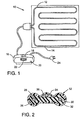
- Blanket 10 includes an elongated heating element 12 that is looped back and forth through channels formed in an electric blanket shell 14 to provide heat evenly across the surface of the blanket in a well-known manner. Although only one heating element is shown which is typically on the order of 100 feet long, two or more heating elements may be included in a single blanket.
- a controller 16 is connected to heating element 12 and includes an on/off switch 18, a start button 20, and an adjustable heat control 22 that enables the operator of blanket 10 to adjust the heat generated by heating element 12. Controller 16 couples blanket 10 to a suitable source of electrical operating power through plug 24.
- Fig. 2 shows a sectional view of heating element 12 of the present invention that is implemented in electric blanket 10.
- Heating element 12 is of a type utilizing a positive temperature coefficient (PTC) material 26 which is extruded between and around a pair of spaced conductors 28 and 30 and which forms a dogbone shape.
- PTC positive temperature coefficient
- a suitable electrically insulating coating 32 is extruded over PTC material 26.
- PTC heating element may vary considerably, preferred embodiments of such a heating element are detailed in U.S. Patent No. 4,277,673 to Kelly, issued on July 7, 1981, entitled ELECTRICALLY CONDUCTIVE SELF-REGULATING ARTICLE, and in U.S. Patent No.
- the PTC material in the heating element has a very high surface resistance, and is comprised of polyethylene, silicone rubber, or the like, having carbon black particles mixed therein in such a manner as to give specific temperature/resistance characteristics.
- each of conductors 28 and 30 have an insulating core over which conductor wire has been helically wound, with each core having been coated with a conducting carbon dispersion, as detailed in U.S. Patent No. 4,309,596 to Crowley.
- the coating applied to each core counteracts the high surface resistance of PTC material 26, resulting in a low resistance electrical interface between PTC material 26 and each of conductors 28 and 30.
- electrical current passes between conductors 28 and 30 and through material 26 therebetween.
- PTC material 26 provides a resistive heating area throughout the entire length of heating element 12 and, although shown in Fig. 3 as discrete parallel resistances, form a single continuous resistance heater between conductors 28 and 30.
- PTC material 26 The formulation of PTC material 26 and the physical dimensions of its extrusion are selected so that the resistance and, thus, the heat dissipation per foot of length are reasonably constant at any given temperature. At low temperatures, the heat dissipation per foot will be greater than at normal room temperatures. When in an overheat or high temperature condition, the heat dissipation will be less than normal. PTC material 26 self-limits to produce a given heat dissipation or wire temperature for every different ambient and insulation system.
- heating element 12 reacts to the new environment and reduces its heat dissipation in that area in an attempt to maintain a reasonably constant temperature.
- heating element 12 of the present invention is a conductive element 34 (Fig. 2) that runs parallel to conductors 28 and 30 throughout the length of the heating element.
- element 34 is a filament or fiber, and is positioned in a gap 36 (somewhat exaggerated in Fig. 2) between PTC material 26 and insulation coating 32. Positioned as such, fiber 34 is in close thermal proximity to conductors 28 and 30.
- conductive fiber 34 is not coated with a conducting carbon dispersion. Therefore, the high surface resistance of PTC material 26 causes conductive fiber 34 to be essentially electrically insulated, resulting in very little leakage current passing between fiber 34 and conductors 28 and 30.
- conductors 28 and 30 are separated by a distance of approximately 0.040 inches, and conductive fiber 34 is separated from each conductor by a distance of approximately 0.031 inches.
- the composition of fiber 34, described below, is such that it breaks when exposed to high temperatures associated with excessive overheating conditions which cannot be compensated for by the self-limiting nature of PTC material 26.
- conductive element 34 there are many types of materials and compositions that can be used for conductive element 34. Any metal, metal alloy, or electrically conductive material, and combinations thereof, can be used, including, but not limited to:
- any metallic or electrically-conductive coated fiber or yarn can be used for conductive fiber 34, including, but not limited to:
- any yarn having any combination of metallic or electrically-conductive fillers can be used for conductive fiber 34, including, but not limited to:
- optical fibers can also be used for conductive fiber 34.
- the second most preferred material is stainless steel fiber (without the polyester yarn).
- the specific type of the second most preferred material that was actually tested consists of 90 strands of 14 micron stainless steel fiber (having a typical melting point of approximately 1500 degrees Celsius), and is available from Bekaert Fibre Technologies as Bekinox #VN-14/IX90/90Z.
- the two above-mentioned most preferred compositions for conductive fiber 34 are preferred because they are strong enough to withstand the normal flexing, handling, and laundering of electric blankets, and are flexible enough so as to not make a blanket too stiff. Furthermore, for reasons discussed in greater detail below, the stranding of the stainless steel is small enough that heat will cause conductive fiber 34 to sever before the blanket fabric can be ignited.
- the polyester in the most preferred embodiment is beneficial in that it adds strength to the stainless steel fiber strands in order to facilitate the manufacturing process.
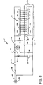
- FIG. 3 shown is a schematic circuit diagram of the safety circuit 37 of the present invention, the majority of which is housed within controller 16 (Fig. 1).
- Plug 24 couples the safety circuit to a suitable source of electrical operating power which is typically AC line voltage.
- a fuse 38 is included which is connected in series with power lead 40 and which serves to interrupt the circuit when the current through it exceeds a predetermined value.
- fuse 38 is rated at 5 amperes which specifies that it will open the circuit if the current is at least 4.5 amperes (90 percent of its rating).
- the rating of fuse 38 is high enough so that it will not blow out due to the normally high inrush currents, typically of about 4 amperes, that are temporarily experienced when power is first supplied to blanket 10.
- on/off switch 18 Connected in series with fuse 38 is on/off switch 18 that is controlled by the operator of blanket 10 (Fig. 1). Switch 18 is closed when in the "on” position so as to couple the rest of the safety circuit to the source of electrical operating power.
- the safety circuit includes a relay comprised of a relay coil 42 and a normally open relay switch 44.
- the relay has a 115 volt AC voltage coil and a single pole switch, and is manufactured by Cornell Dubilier Corporation.
- start button 20 Coupled to relay coil 42 is start button 20 which, when momentarily pressed by the operator at a time when on/off switch 18 is closed ("on"), causes a completed circuit to be formed whereby relay coil 42 will be energized and will have a sufficient current through it to cause relay switch 44 to close.
- start button 20 After the start button 20 is released, the completed circuit formed with conductive fiber 34 (described below), although inducing less current through relay coil 42 than start button 20, will thereafter cause relay coil 42 to be sufficiently energized so as to keep relay switch 44 closed.
- start button 20 is a single pole single throw normally open momentary switch that is manufactured by Grayhill Corporation.
- the safety circuit includes a gas tube 46 which is energized when relay switch 44 and on/off switch 18 are closed. Gas tube 46 emits light when energized as such, and serves as an indicator light to indicate that the electric blanket is in use.
- a current limiting resistor RI In series with gas tube 46 is a current limiting resistor RI.
- gas tube 46 is a neon bulb
- resistor RI is a 62 K0hm resistor
- the combination of tube 46 and resistor RI is rated at 120 volts.
- thermostat 48 Also included in the safety circuit is a bimetallic thermostat 48 that is in close physical and thermal proximity to a resistor R2. Resistor R2 is connected so that it is energized, and thus generates heat, whenever heating element 12 is generating heat, and is a 62 KOhm carbon resistor in the preferred embodiment.
- thermostat 48 operates like a switch in relation to its temperature which is determined by the heat emitted by resistor R2. In particular, thermostat 48 is "closed” when the temperature thereof is below a threshold value, and is “opened” when the threshold temperature is exceeded. The threshold temperature, and thus the sensitivity of thermostat 48, is controlled by adjustable heat control 22 of controller 16 (Fig. 1).
- thermostat 48 When the threshold temperature is exceeded and thermostat 48 is opened, neither resistor R2 nor heating element 12 is energized, causing them to cease generating heat and to begin to cool. When resistor R2 has cooled to the point where the temperature of thermostat 48 falls below the threshold temperature, thermostat 48 closes, causing resistor R2 and heating element 12 to once again be energized. This cyclic nature enables the operator of blanket 10 to effectively control the amount of heat generated by heating element 12 by means of adjustable heat control 22.
- Fig. 3 also shows heating element 12.
- heating element 12 When on/off switch 18, relay switch 44, and bimetallic thermostat 48 are closed, heating element 12 is energized and generates heat by means of current passing between conductors 28 and 30 through the resistive PTC material 26. For reasons discussed below, the two ends 50 and 52 of conductor 28 are coupled together, and the two ends 54 and 56 of conductor 30 are coupled together.
- heating element 12 includes conductive element or fiber 34 which is coupled to the operating power and, in Fig, 3, extends from point 58 to point 60 and through the length of heating element 12.
- Conductive fiber 34 electrically insulated from PTC material 26 and conductors 28 and 30, is coupled to relay coil 42 and forms a completed circuit path which conducts current when on/off switch 18 is closed. As mentioned above, this current energizes relay coil 42, thus keeping relay switch 44 closed.
- Electric blankets such as the one described above, are conventionally used in much the same manner as nonelectric blankets.
- the heating elements contained in such electric blankets be made of suitable dimensions and materials so that they can be repeatedly flexed without breaking or resulting in other problems.
- a heating element will be damaged to the point where severe overheating conditions are created if the blanket is connected to operating power. Such severe overheating conditions may burn the heating element and cause a dangerous situation to develop.
- Examples of such damage to a heating element include when breaks or faults develop in one or more conductors contained in the heating element, or when a short is created between the conductors.
- the severe overheating conditions are often caused by electrical arcs that can reach temperatures of thousands of degrees Celsius.
- the above-described safety circuit of the present invention has been found to prevent or eliminate problems of this type.
- a single break occurs in either conductor 28 or 30
- only a relatively small voltage drop, if any, is created across the break since the ends of each conductor are connected together and coupled to the operating power.
- the exact magnitude of this voltage drop is dependant on the location of the break with respect to the ends of the conductor.
- a break at the middle of conductor 28 or 30 produces no voltage drop across the break, whereas a break at one end of the conductor produces a maximum voltage drop equal to the total voltage drop through the length of the conductor.
- the voltage drop through the conductor is dependant on the internal resistance of the conductor which is kept sufficiently low so that even the maximum voltage drop situation does not create an electrical arc at the break.
- the safety circuit prevents a single break in one or both of conductors 28 and 30 from creating an overheating condition.
- Conductive fiber 34 of the safety circuit of the present invention prevents a hazardous situation from developing when two breaks occur in either conductor 28 or 30.
- fiber 34 is in close physical and thermal proximity to conductors 28 and 30 and is formed of material which causes it to sever when exposed to high temperatures.
- conductive fiber 34 will not break during normal operation of blanket 10 when heating element 12 is generating the desired amount of heat, but will quickly break if excessive overheating conditions develop such as that caused by an electrical arc.
- Such a break in conductive fiber 34 will open the circuit path which normally conducts current through relay coil 42. The break will thus de-energize relay coil 42, causing relay switch 44 to open and to discontinue operating power to heating element 12.
- the materials used for conductive fiber 34, described above, are selected so that fiber 34 will sever, and the operating power will be discontinued, before any hazardous situation develops.
- conductive fiber 34 and the safety circuit of the present invention can be easily implemented to protect against overheating conditions in almost any situation. Furthermore, the benefits of such a safety circuit can be realized in all types of electrical circuits, electric devices, and power cords, regardless of whether the operating power is AC or DC.
Landscapes
- Engineering & Computer Science (AREA)
- Textile Engineering (AREA)
- Control Of Resistance Heating (AREA)
- Resistance Heating (AREA)
- Protection Of Static Devices (AREA)
- Control Of Temperature (AREA)
- Fuses (AREA)
- Control Of Combustion (AREA)
- Control Of Electric Motors In General (AREA)
Applications Claiming Priority (2)
| Application Number | Priority Date | Filing Date | Title |
|---|---|---|---|
| US08/652,898 US5801914A (en) | 1996-05-23 | 1996-05-23 | Electrical safety circuit with a breakable conductive element |
| US652898 | 2000-08-31 |
Publications (2)
| Publication Number | Publication Date |
|---|---|
| EP0809417A2 true EP0809417A2 (de) | 1997-11-26 |
| EP0809417A3 EP0809417A3 (de) | 1998-02-04 |
Family
ID=24618657
Family Applications (1)
| Application Number | Title | Priority Date | Filing Date |
|---|---|---|---|
| EP97303563A Withdrawn EP0809417A3 (de) | 1996-05-23 | 1997-05-23 | Sicherheitsschaltung für elektrische Vorrichtungen |
Country Status (9)
| Country | Link |
|---|---|
| US (1) | US5801914A (de) |
| EP (1) | EP0809417A3 (de) |
| JP (1) | JP3023332B2 (de) |
| KR (1) | KR970078742A (de) |
| CN (1) | CN1061790C (de) |
| AR (1) | AR003660A1 (de) |
| AU (1) | AU2357597A (de) |
| CA (1) | CA2205819A1 (de) |
| MX (1) | MX9703836A (de) |
Cited By (4)
| Publication number | Priority date | Publication date | Assignee | Title |
|---|---|---|---|---|
| DE19827374A1 (de) * | 1998-06-19 | 1999-12-30 | Daimler Chrysler Ag | Sicherungselement für elektrische Anlagen |
| WO2004010736A1 (en) * | 2002-07-20 | 2004-01-29 | Heat Trace Limited | Electrical heating cable |
| GB2514385A (en) * | 2013-05-22 | 2014-11-26 | Heat Trace Ltd | Heating cable |
| CN109716859A (zh) * | 2017-08-11 | 2019-05-03 | Sh 科技有限公司 | 发热单元以及包括其的发热模块 |
Families Citing this family (37)
| Publication number | Priority date | Publication date | Assignee | Title |
|---|---|---|---|---|
| US5900999A (en) * | 1997-01-09 | 1999-05-04 | Donnelly Corporation | Housing with integral electrical connectors for a rearview mirror actuator assembly |
| TW371379B (en) * | 1997-01-09 | 1999-10-01 | Daifuku Kk | Protective device of non-contact feeder system |
| US6229123B1 (en) | 1998-09-25 | 2001-05-08 | Thermosoft International Corporation | Soft electrical textile heater and method of assembly |
| US6452138B1 (en) * | 1998-09-25 | 2002-09-17 | Thermosoft International Corporation | Multi-conductor soft heating element |
| AU756477C (en) * | 1998-12-23 | 2003-09-11 | Fisher & Paykel Healthcare Limited | Fault protection system for a respiratory conduit heater element |
| US7053344B1 (en) | 2000-01-24 | 2006-05-30 | Illinois Tool Works Inc | Self regulating flexible heater |
| US6884965B2 (en) * | 1999-01-25 | 2005-04-26 | Illinois Tool Works Inc. | Flexible heater device |
| US7202444B2 (en) * | 1999-01-25 | 2007-04-10 | Illinois Tool Works Inc. | Flexible seat heater |
| US6563094B2 (en) | 1999-05-11 | 2003-05-13 | Thermosoft International Corporation | Soft electrical heater with continuous temperature sensing |
| US6713733B2 (en) | 1999-05-11 | 2004-03-30 | Thermosoft International Corporation | Textile heater with continuous temperature sensing and hot spot detection |
| US6403935B2 (en) * | 1999-05-11 | 2002-06-11 | Thermosoft International Corporation | Soft heating element and method of its electrical termination |
| AU4847700A (en) | 1999-05-14 | 2000-12-05 | Asuk Technologies, Llc | Electrical heating devices and resettable fuses |
| WO2003011000A1 (en) * | 2001-07-05 | 2003-02-06 | King's Metal Fiber Technologies Co., Ltd. | Heating apparatus having heating line combined with soft matrix |
| US6770854B1 (en) * | 2001-08-29 | 2004-08-03 | Inotec Incorporated | Electric blanket and system and method for making an electric blanket |
| DE10234389A1 (de) * | 2002-07-23 | 2004-02-05 | Alcoa Fujikura Gesellschaft mit beschränkter Haftung | Leitungsanordnung für Bordnetze von Fahrzeugen |
| US20040070904A1 (en) * | 2002-10-11 | 2004-04-15 | Carr Sheldon P. | Over-voltage protection arrangement for a low voltage power supply |
| US6713724B1 (en) | 2002-10-11 | 2004-03-30 | Perfect Fit Industries, Inc. | Heating element arrangement for an electric blanket or the like |
| US6888108B2 (en) | 2002-10-11 | 2005-05-03 | Perfect Fit Industries, Inc. | Low voltage power supply system for an electric blanket or the like |
| US7306283B2 (en) | 2002-11-21 | 2007-12-11 | W.E.T. Automotive Systems Ag | Heater for an automotive vehicle and method of forming same |
| EP1639614A1 (de) * | 2003-06-24 | 2006-03-29 | Koninklijke Philips Electronics N.V. | Dehnbarer gewebeschalter |
| GB0322047D0 (en) * | 2003-09-20 | 2003-10-22 | Heat Trace Ltd | Method of processing parallel resistance electrical heating cable |
| US6958463B1 (en) | 2004-04-23 | 2005-10-25 | Thermosoft International Corporation | Heater with simultaneous hot spot and mechanical intrusion protection |
| US7889733B2 (en) | 2004-04-28 | 2011-02-15 | Cisco Technology, Inc. | Intelligent adjunct network device |
| FI120926B (fi) * | 2008-01-25 | 2010-04-30 | Abb Oy | Kuormituksenvalvontalaitteisto |
| US20100314381A1 (en) * | 2008-01-28 | 2010-12-16 | Ching Chuan Wang | Heating device |
| WO2011149680A1 (en) | 2010-05-27 | 2011-12-01 | W.E.T. Automotive Systems, Ltd. | Heater for an automotive vehicle and method of forming same |
| US9191997B2 (en) | 2010-10-19 | 2015-11-17 | Gentherm Gmbh | Electrical conductor |
| DE102012000977A1 (de) | 2011-04-06 | 2012-10-11 | W.E.T. Automotive Systems Ag | Heizeinrichtung für komplex geformte Oberflächen |
| DE102011121979A1 (de) | 2011-09-14 | 2012-11-22 | W.E.T. Automotive Systems Ag | Temperier-Einrichtung |
| US10201039B2 (en) | 2012-01-20 | 2019-02-05 | Gentherm Gmbh | Felt heater and method of making |
| DE202013003491U1 (de) | 2012-06-18 | 2013-09-20 | W.E.T. Automotive Systems Ag | Flächengebilde mit elektrischer Funktion |
| US10772510B2 (en) * | 2012-08-22 | 2020-09-15 | Midmark Corporation | Vital signs monitor for controlling power-adjustable examination table |
| DE102012017047A1 (de) | 2012-08-29 | 2014-03-06 | W.E.T. Automotive Systems Ag | Elektrische Heizeinrichtung |
| DE102012024903A1 (de) | 2012-12-20 | 2014-06-26 | W.E.T. Automotive Systems Ag | Flächengebilde mit elektrischen Funktionselementen |
| CN107898273A (zh) * | 2017-12-18 | 2018-04-13 | 无锡优耐特能源科技有限公司 | 一种安全防护脚垫及安全继电器装置 |
| US11526184B2 (en) | 2018-04-10 | 2022-12-13 | Lear Corporation | Vehicle seat including a heating mat having overheating prevention and protection |
| JP7616113B2 (ja) * | 2022-02-07 | 2025-01-17 | 株式会社ダイフク | 給電システム |
Family Cites Families (39)
| Publication number | Priority date | Publication date | Assignee | Title |
|---|---|---|---|---|
| US3114825A (en) * | 1961-01-30 | 1963-12-17 | Gen Electric | Electric heating pad |
| NL288627A (de) * | 1962-02-21 | |||
| US3215896A (en) * | 1962-10-04 | 1965-11-02 | Gen Electric | Fast response overload protection circuit |
| US3325718A (en) * | 1963-12-04 | 1967-06-13 | Gen Lab Associates Inc | Protective circuit for vibrator type d.c.-a.c. converters |
| US3493815A (en) * | 1967-07-19 | 1970-02-03 | Gen Electric | Electric protective system |
| US3600634A (en) * | 1969-12-16 | 1971-08-17 | Integrated Systems Inc | Protective control circuit against transient voltages |
| US3628093A (en) * | 1970-04-13 | 1971-12-14 | Northern Electric Co | Thermostat overheat protection system for an electric appliance such as a blanket |
| USRE28656E (en) * | 1971-10-26 | 1975-12-16 | Thermostatless blanket control circuit | |
| US3845355A (en) * | 1973-05-04 | 1974-10-29 | Borg Warner | Fault protection circuit for an adjustable motorized hospital bed |
| US3878434A (en) * | 1973-12-10 | 1975-04-15 | Leeds & Northrup Co | Power-limiting electrical barrier device |
| US3968407A (en) * | 1974-03-27 | 1976-07-06 | Petrolite Corporation | Redundant intrinsic safety barrier |
| FR2315752A1 (fr) * | 1975-06-24 | 1977-01-21 | Babled Frederic | Cable auto-protege et montage de securite en comportant application |
| US4034185A (en) * | 1975-09-02 | 1977-07-05 | Northern Electric Company | Electric blanket control circuit |
| GB1599709A (en) * | 1978-01-31 | 1981-10-07 | Dreamland Electrical Appliance | Heating circuits |
| US4277673A (en) * | 1979-03-26 | 1981-07-07 | E-B Industries, Inc. | Electrically conductive self-regulating article |
| US4450496A (en) * | 1979-08-16 | 1984-05-22 | Raychem Corporation | Protection of certain electrical systems by use of PTC device |
| CA1156300A (en) * | 1980-04-01 | 1983-11-01 | Gordon S. Carlson | Electric blanket safety circuit |
| US4271350A (en) * | 1980-05-19 | 1981-06-02 | Sunbeam Corporation | Blanket wire utilizing positive temperature coefficient resistance heater |
| US4309597A (en) * | 1980-05-19 | 1982-01-05 | Sunbeam Corporation | Blanket wire utilizing positive temperature coefficient resistance heater |
| US4309596A (en) * | 1980-06-24 | 1982-01-05 | Sunbeam Corporation | Flexible self-limiting heating cable |
| US4436986A (en) * | 1981-11-23 | 1984-03-13 | Sunbeam Corporation | Electric blanket safety circuit |
| US4439801A (en) * | 1982-04-12 | 1984-03-27 | Xenell Corporation | Electrical load imbalance detection and protection apparatus |
| CA1235450A (en) * | 1983-05-11 | 1988-04-19 | Kazunori Ishii | Flexible heating cable |
| US4577094A (en) * | 1983-10-05 | 1986-03-18 | Fieldcrest Mills, Inc. | Electrical heating apparatus protected against an overheating condition |
| US4550358A (en) * | 1984-02-13 | 1985-10-29 | Sunbeam Corporation | Protective circuit for portable electric appliances |
| US4547658A (en) * | 1984-06-13 | 1985-10-15 | Sunbeam Corporation | Multiple heat fusing wire circuit for underblankets |
| CA1244863A (en) * | 1984-12-06 | 1988-11-15 | George C. Crowley | Electric blanket or pad having improved positive temperature coefficient heater circuit |
| JPS62100968A (ja) * | 1985-10-29 | 1987-05-11 | 東レ株式会社 | 糸状発熱体及びその製造方法 |
| US5143649A (en) * | 1985-12-06 | 1992-09-01 | Sunbeam Corporation | PTC compositions containing low molecular weight polymer molecules for reduced annealing |
| US4822983A (en) * | 1986-12-05 | 1989-04-18 | Raychem Corporation | Electrical heaters |
| US5081339A (en) * | 1990-06-01 | 1992-01-14 | Sunbeam Corporation | Water bed heater |
| CN2096180U (zh) * | 1991-07-04 | 1992-02-12 | 张福来 | 电热毯安全保护器 |
| US5451747A (en) * | 1992-03-03 | 1995-09-19 | Sunbeam Corporation | Flexible self-regulating heating pad combination and associated method |
| GB9208182D0 (en) * | 1992-04-11 | 1992-05-27 | Cole Graham M | Improvements in or relating to electrically heated panels |
| CN2133110Y (zh) * | 1992-07-14 | 1993-05-12 | 大连电热毯厂 | 一种电热毯断电保护温控开关 |
| US5369247A (en) * | 1992-10-29 | 1994-11-29 | Doljack; Frank A. | Self-regulating electrical heater system and method |
| US5420397A (en) * | 1992-12-15 | 1995-05-30 | Micro Weiss Electronics, Inc. | Control device and safety circuit for heating pads with PTC heater |
| US5424895A (en) * | 1993-08-17 | 1995-06-13 | Gaston; William R. | Electrical wiring system with overtemperature protection |
| US5412181A (en) * | 1993-12-27 | 1995-05-02 | The B. F. Goodrich Company | Variable power density heating using stranded resistance wire |
-
1996
- 1996-05-23 US US08/652,898 patent/US5801914A/en not_active Expired - Fee Related
-
1997
- 1997-05-22 AU AU23575/97A patent/AU2357597A/en not_active Abandoned
- 1997-05-22 CA CA002205819A patent/CA2205819A1/en not_active Abandoned
- 1997-05-23 MX MX9703836A patent/MX9703836A/es unknown
- 1997-05-23 JP JP9169374A patent/JP3023332B2/ja not_active Expired - Lifetime
- 1997-05-23 EP EP97303563A patent/EP0809417A3/de not_active Withdrawn
- 1997-05-23 AR ARP970102193A patent/AR003660A1/es unknown
- 1997-05-23 CN CN97114836A patent/CN1061790C/zh not_active Expired - Fee Related
- 1997-05-23 KR KR1019970020111A patent/KR970078742A/ko not_active Withdrawn
Cited By (6)
| Publication number | Priority date | Publication date | Assignee | Title |
|---|---|---|---|---|
| DE19827374A1 (de) * | 1998-06-19 | 1999-12-30 | Daimler Chrysler Ag | Sicherungselement für elektrische Anlagen |
| DE19827374C2 (de) * | 1998-06-19 | 2001-05-23 | Daimler Chrysler Ag | Sicherungselement für elektrische Anlagen |
| WO2004010736A1 (en) * | 2002-07-20 | 2004-01-29 | Heat Trace Limited | Electrical heating cable |
| GB2514385A (en) * | 2013-05-22 | 2014-11-26 | Heat Trace Ltd | Heating cable |
| CN109716859A (zh) * | 2017-08-11 | 2019-05-03 | Sh 科技有限公司 | 发热单元以及包括其的发热模块 |
| EP3468300A4 (de) * | 2017-08-11 | 2019-09-18 | SH Tech Co., Ltd. | Heizeinheit und heizmodul damit |
Also Published As
| Publication number | Publication date |
|---|---|
| CN1061790C (zh) | 2001-02-07 |
| AU2357597A (en) | 1997-11-27 |
| MX9703836A (es) | 1998-04-30 |
| CA2205819A1 (en) | 1997-11-23 |
| CN1170261A (zh) | 1998-01-14 |
| AR003660A1 (es) | 1998-09-09 |
| EP0809417A3 (de) | 1998-02-04 |
| JPH10144192A (ja) | 1998-05-29 |
| JP3023332B2 (ja) | 2000-03-21 |
| US5801914A (en) | 1998-09-01 |
| KR970078742A (ko) | 1997-12-12 |
Similar Documents
| Publication | Publication Date | Title |
|---|---|---|
| US5801914A (en) | Electrical safety circuit with a breakable conductive element | |
| MXPA97003836A (en) | Electric device security circuit | |
| US4436986A (en) | Electric blanket safety circuit | |
| KR100586120B1 (ko) | 전기담요용 가열소자 | |
| EP0125913B1 (de) | Flexibler Heizdraht | |
| EP0270370B1 (de) | Elektrische Heizgeräte | |
| US3628093A (en) | Thermostat overheat protection system for an electric appliance such as a blanket | |
| GB2330463A (en) | Electrical assembly for blanket or heating pad | |
| US4278874A (en) | Heating circuits | |
| US4491723A (en) | Heating circuit with overheat safety control feature | |
| EP1645167B2 (de) | Heizdecke | |
| CA1156300A (en) | Electric blanket safety circuit | |
| EP0562850A2 (de) | Heizvorrichtung | |
| CA1244863A (en) | Electric blanket or pad having improved positive temperature coefficient heater circuit | |
| GB2047487A (en) | Heating circuits | |
| HK1002383A (en) | Safety circuit for electrical devices | |
| GB2028608A (en) | Heating circuits | |
| GB2028607A (en) | Heating circuits | |
| GB1566005A (en) | Heating circuits for electrically heated blankets or pads | |
| JPH076867A (ja) | 溶融型三重制御i線式絶縁電熱線 | |
| GB2154816A (en) | Electrical heating circuits | |
| GB1588783A (en) | Heating circuits | |
| GB2157514A (en) | Electrical heating circuits | |
| KR19980047890A (ko) | 피티시 서미스터를 이용한 전기 부하의 과열 방지 방법 | |
| GB2154817A (en) | Electrical heating circuits |
Legal Events
| Date | Code | Title | Description |
|---|---|---|---|
| PUAI | Public reference made under article 153(3) epc to a published international application that has entered the european phase |
Free format text: ORIGINAL CODE: 0009012 |
|
| AK | Designated contracting states |
Kind code of ref document: A2 Designated state(s): AT BE CH DE DK ES FI FR GB GR IE IT LI LU MC NL PT SE |
|
| AX | Request for extension of the european patent |
Free format text: AL PAYMENT 970610;LT PAYMENT 970610;LV PAYMENT 970610;RO PAYMENT 970610;SI PAYMENT 970610 |
|
| PUAL | Search report despatched |
Free format text: ORIGINAL CODE: 0009013 |
|
| AK | Designated contracting states |
Kind code of ref document: A3 Designated state(s): AT BE CH DE DK ES FI FR GB GR IE IT LI LU MC NL PT SE |
|
| AX | Request for extension of the european patent |
Free format text: AL PAYMENT 970610;LT PAYMENT 970610;LV PAYMENT 970610;RO PAYMENT 970610;SI PAYMENT 970610 |
|
| 17P | Request for examination filed |
Effective date: 19980213 |
|
| STAA | Information on the status of an ep patent application or granted ep patent |
Free format text: STATUS: THE APPLICATION IS DEEMED TO BE WITHDRAWN |
|
| 18D | Application deemed to be withdrawn |
Effective date: 20011204 |
|
| REG | Reference to a national code |
Ref country code: HK Ref legal event code: WD Ref document number: 1002383 Country of ref document: HK |