EP0809580B1 - Dispositif servant a la transmission de signaux electriques entre des composants pouvant tourner l'un par rapport a l'autre - Google Patents
Dispositif servant a la transmission de signaux electriques entre des composants pouvant tourner l'un par rapport a l'autre Download PDFInfo
- Publication number
- EP0809580B1 EP0809580B1 EP95942640A EP95942640A EP0809580B1 EP 0809580 B1 EP0809580 B1 EP 0809580B1 EP 95942640 A EP95942640 A EP 95942640A EP 95942640 A EP95942640 A EP 95942640A EP 0809580 B1 EP0809580 B1 EP 0809580B1
- Authority
- EP
- European Patent Office
- Prior art keywords
- hub
- electric lead
- chamber
- rotatable
- loop
- Prior art date
- Legal status (The legal status is an assumption and is not a legal conclusion. Google has not performed a legal analysis and makes no representation as to the accuracy of the status listed.)
- Expired - Lifetime
Links
Images


Classifications
-
- B—PERFORMING OPERATIONS; TRANSPORTING
- B60—VEHICLES IN GENERAL
- B60R—VEHICLES, VEHICLE FITTINGS, OR VEHICLE PARTS, NOT OTHERWISE PROVIDED FOR
- B60R16/00—Electric or fluid circuits specially adapted for vehicles and not otherwise provided for; Arrangement of elements of electric or fluid circuits specially adapted for vehicles and not otherwise provided for
- B60R16/02—Electric or fluid circuits specially adapted for vehicles and not otherwise provided for; Arrangement of elements of electric or fluid circuits specially adapted for vehicles and not otherwise provided for electric constitutive elements
- B60R16/023—Electric or fluid circuits specially adapted for vehicles and not otherwise provided for; Arrangement of elements of electric or fluid circuits specially adapted for vehicles and not otherwise provided for electric constitutive elements for transmission of signals between vehicle parts or subsystems
- B60R16/027—Electric or fluid circuits specially adapted for vehicles and not otherwise provided for; Arrangement of elements of electric or fluid circuits specially adapted for vehicles and not otherwise provided for electric constitutive elements for transmission of signals between vehicle parts or subsystems between relatively movable parts of the vehicle, e.g. between steering wheel and column
-
- H—ELECTRICITY
- H01—ELECTRIC ELEMENTS
- H01R—ELECTRICALLY-CONDUCTIVE CONNECTIONS; STRUCTURAL ASSOCIATIONS OF A PLURALITY OF MUTUALLY-INSULATED ELECTRICAL CONNECTING ELEMENTS; COUPLING DEVICES; CURRENT COLLECTORS
- H01R35/00—Flexible or turnable line connectors, i.e. the rotation angle being limited
- H01R35/02—Flexible line connectors without frictional contact members
- H01R35/025—Flexible line connectors without frictional contact members having a flexible conductor wound around a rotation axis
Definitions
- the invention relates to a device according to the preamble of claim 1.
- Such transmission facilities are used, for example, in vehicle steering systems, around the signals of the functional elements arranged on or in the steering wheel transferred to.
- DE-OS 35 37 783 is a device for signal transmission shown in which an electrical line on a fixed and a rotatable component is attached. There is a between the stationary and the rotatable component arranged with a recessed loose guide ring.
- the electrical line is at least partially around Guide ring around and through the recess of the guide ring guided and is within the guide ring around that rotatable component can be wound.
- the wound part and the part around the guide ring become part of the component guided part of the electrical line each shortened or lengthened so that the guide ring accordingly the movement of the electrical line is rotated.
- the electrical line is open the rotatable component, in the other extreme position the electrical line is unwound and between the guide ring and the stationary component.
- the device described in DE-OS 35 37 783 for Signal transmission has the disadvantage that the possible Rotational movement compared to the length of the electrical Line is low.
- DE-A-4 111 699 is a transmission device known for the effective length of a flexible electrical conductor is reduced without the number of the rotations of the rotor must be reduced. Reached is that by a in the space between the rotor and a fixed housing arranged intermediate link, which in rotates in the same direction and in synchronism with the rotor, and on which a guide roller is rotatably mounted.
- the invention is therefore based on the object of a device for transmitting electrical signals between to create mutually rotatable components in which the necessary length of the electrical line for one predetermined range of rotation compared to previously known solutions is reduced.
- the electrical line connections and the routing of the electrical line is carried out that the electrical line in the two end positions of the hub when rotating the hub clockwise or counterclockwise Clockwise in the opposite direction the hub is wound up while the electrical wire is unwound from the hub in the middle position.
- a first chamber for receiving the electrical wound on the hub Line and a second chamber for the processed, loop-shaped electrical line provided.
- the loop of the electrical line only by 180 °.
- the housing can be on the opposite side of this room Side omitted.
- This free space can e.g. in a steering spindle can be used for other components.
- the chambers is in one embodiment between the hub and a fixed housing fixed annular partition with an opening for the implementation of the electrical line provided and on the outside of the partition is next to the opening electrical line connection provided.
- the first chamber is then formed between the hub and the bulkhead while the second chamber concentrically between them the fixed housing and the partition.
- the electrical line is in the two extreme positions the first chamber wound on the hub while in the middle position of the hub as a loop in the second Chamber lies.
- the second chamber provided on the side of the fixed housing and at the transition the first in the second chamber is the electrical one Line connection provided on a fixed Component is to be attached.
- the first chamber is the space between the fixed housing and the hub.
- the second chamber closes the first chamber on the side. In the middle position of the hub the electrical cable is in the form of a loop lateral second chamber.
- Loop guide can be a connector between the fixed housing and the partition be provided.
- Another expedient embodiment of the invention provides before that the loop of the electrical wire permanent tensile element is provided. In order to is achieved that in the absence of a torque on the Hub is held in its middle position.
- Tension element can e.g. a tension spring can be provided.
- the hub-side electrical line connection is rotatably attached to the hub and in particular rotatable about an axis parallel to the hub axis is.
- the housing of the device according to the invention has in an embodiment a circular cross section on.
- the housing an annular cross section with one on one Side on a string of the circle-trending flat wall on.
- this is a section opposite to that with circular Cross-section has been reduced for the unwound Cable is not needed.
- This gained space can e.g. B. when used on a steering column of a motor vehicle can be used for the installation of other components.
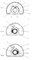
- the device according to the invention has a housing 1 and a hub 9, e.g. B. a steering wheel hub, between which an electrical line 2 extends. Between the Hub 9 and housing 1 are concentric with hub 9 and to the housing 1 a fixed partition 10, whereby an inner first chamber 3 and an outer second Chamber 4 are formed, which are concentric with each other lie.
- the intermediate wall 10 has an opening 11, through which the electrical line 2 is guided.
- the hub 9 is in a central position.
- this line 2 is completely from the hub unwound and extends through the opening 11 of a line connection 5 on the hub 9 in the second chamber 4.
- the line is a loop in this chamber the wall of the housing 1 and the intermediate wall 10 into one Line connection 6 guided on the fixed partition.
- the line connections 5 and 6 are in this Middle position of the hub 9 directly opposite.
- Fig. 2 shows the hub in this direction of rotation in its end position. The line is now almost completely wound on the hub 9.
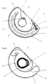
- FIG. 1a there is a housing 21 provided that essentially as in FIGS. 1 to 3 has a circular cylindrical cross section, which on a But side is flattened so that there is a flat wall 22.
- the partition also extends from this 10a in the direction of the hub 9.
- the first chamber 3 is therefore in contrast to the exemplary embodiment in FIGS. 1 to 3 not just from the partition but from the partition 10a and the flat wall 22 formed as part of the housing.
- the flattening of the cylinder cross section next to the flat one Wall 22 created free space can be used for housing other components can be used.
- Figures 2a and 3a show the hub 9 in both in analogy to FIGS. 2 and 3 Direction of rotation in its end position.
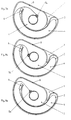
- FIG. 4 shows again the Center position of the hub, in which the line from the hub is unwound and is a loop in the second chamber located.
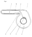
- FIG. 5 is an intermediate wall 10 provided, which is provided with a loop guide.
- a connector 8 between serves as a loop guide the housing 1 and the intermediate wall 10. Through this connector 8 will guide the loop in the second Chamber further improved.
- a tension spring 7 is provided, which strives to Loop in the second chamber in its end position and thereby to keep the hub 9 in its central position.
- the mainspring is attached to two bolts 12, 13. During the bolt 12 is firmly arranged in the housing, the bolt 13 can within the second chamber 4 along a guideway 14 move.
- the hub 9 is shown in its central position, in which the line is almost completely in Loop shape is located in the second chamber 4.
- This Middle position is due to the almost relaxed tension spring 7 fixed, which is shown here in simplified form.
- the hub 9 When turning the hub 9 clockwise or counterclockwise the line is pulled out of the chamber 4 and wound as shown in Fig. 6 for the clockwise rotation, on the hub 9.
- the loop takes the Bolt 13 with, whereby the tension spring 7 is tensioned.
- the tensioned tension spring will return the hub into the Supported center position, in which the mainspring is again in the position shown in Fig. 5.
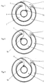
- FIGS. 5 and 6 show Figures 5a and 6a.
- this embodiment is similar to the embodiment of Figures 1a to 3a shows a housing with a circular cylinder cross section flattened on one side intended. That forms on this side Connector 8 between the housing 1 and the partition 10 simultaneously the housing wall.
- FIG. 6a shows the hub 9 in a simplified representation in their end position when turning clockwise.
- the line is laid when the hub 9 is turned clockwise at line connection 5 directly from the connection point from the tangential direction to the hub.
- the hub 9 turns counterclockwise the line first deflected by approx. 180 ° and only then lies down the hub on.
- the line connection 6 is in the embodiment 1 to 3 the line at on the hub 9 coiled line in both directions of rotation Connection point deflected by 180 °. The line will go to Line connections 5 and 6 in these cases additionally Bending stressed.
- Fig. 8 shows that counter to the beginning of the rotation of the hub clockwise the line connection 5 through the Line 9 is rotated into a right position, so that too in this direction of rotation onto the line at the connection point because of the tangential contact with the hub only pulling forces act.
- Figures 10 to 12 is the position of the rotatable Line connection 6a for different hub positions shown. 10 shows the center position of the hub, in which the line routing at line connection 6a Line routing at line connection 6 in FIG. 1 corresponds. In the end position shown in FIG The hub when turning counterclockwise is the Line connection rotated by 180 °, so that the line only around Is bent 180 ° while in the comparable position 2 must be bent through approximately 360 ° to the hub to lie on.
Landscapes
- Engineering & Computer Science (AREA)
- Mechanical Engineering (AREA)
- Steering Controls (AREA)
- Near-Field Transmission Systems (AREA)
- Power Steering Mechanism (AREA)
Claims (15)
- Dispositif pour transmettre des signaux électriques entre des composants, qui peuvent tourner les uns par rapport aux autres, notamment dans le cas de dispositifs de direction pour des véhicules automobiles, comportant un moyeu pouvant tourner (9), qui est entouré par un boitier fixe (1), et comportant au moins un conducteur électrique (2), qui est relié, par l'une de ses extrémités, au moyeu pouvant tourner (9) et dont l'autre extrémité est reliée à un composant fixe,
caractérisé en ce
que les bornes électriques (5, 6) et les guides (10, 11) du conducteur électrique (2) sont agencés de telle sorte que le conducteur électrique (2) est enroulé dans des directions respectivement opposées sur le moyeu (9), dans les deux positions d'extrémité du moyeu (9), lors d'une rotation de ce moyeu (9) dans le sens des aiguilles d'une montre et en sens inverse des aiguilles d'une montre, tandis que le conducteur électrique (2) est déroulé du moyeu (9) lorsque ce dernier est dans sa position médiane. - Dispositif selon la revendication 1, caractérisé en ce qu'il est prévu une première chambre (3) pour loger le conducteur électrique (2) enroulé sur le moyeu (9) et une seconde chambre (4) pour le conducteur électrique (2) déroulé, qui s'étend sous la forme d'une boucle.
- Dispositif selon la revendication 1 ou 2, caractérisé en ce qu'entre le moyeu (9) et un boítier fixe (1) est fixée une paroi intercalaire annulaire fixe (10, 10a) comportant une ouverture (11) pour le passage du conducteur électrique (2) et qu'une borne électrique (6) du conducteur est prévue sur la face extérieure de la paroi intercalaire (10, 10a) à côté de l'ouverture (11).
- Dispositif selon au moins l'une des revendications précédentes, caractérisé en ce que la seconde chambre (4) est prévue entre le boitier fixe (1) et la paroi intercalaire (10).
- Dispositif selon au moins l'une des revendications précédentes, caractérisé en ce que la seconde chambre (4) est prévue latéralement sur le boitier fixe (1) et qu'une borne électrique (6) du conducteur est prévue dans la seconde chambre (4), au niveau de la jonction entre la première chambre (3) et cette seconde chambre.
- Dispositif selon au moins l'une des revendications précédentes, caractérisé en ce que dans la seconde chambre (4) est prévu un guide de boucle (8) servant à déterminer le sens dans lequel s'étend la boucle du conducteur électrique (2).
- Dispositif selon la revendication 6, caractérisé en ce qu'il est prévu comme guide de boucle, un élément de liaison (8) entre le boitier fixe (1) et la paroi intercalaire (10).
- Dispositif selon au moins l'une des revendications précédentes, caractérisé en ce qu'il est prévu un élément (7) qui sollicite en permanence en traction la boucle du conducteur électrique (2).
- Dispositif selon la revendication 8, caractérisé en ce qu'un ressort de traction (7) est disposé entre le boitier fixe (1) et la boucle du conducteur électrique (2).
- Dispositif selon au moins l'une des revendications précédentes, caractérisé en ce que la borne électrique (5a) du conducteur, située du côté du moyeu, est fixée de manière à pouvoir tourner sur le moyeu (9).
- Dispositif selon la revendication 10, caractérisé en ce que la borne électrique (5a) du conducteur peut tourner sur le moyeu (9) autour d'un axe parallèle à l'axe du moyeu.
- Dispositif selon au moins l'une des revendications précédentes, caractérisé en ce que la borne électrique (6a) du conducteur est montée de manière à pouvoir tourner sur le composant fixe.
- Dispositif selon la revendication 12, caractérisé en ce que la borne électrique (6a) de conducteur est montée de manière à pouvoir tourner sur le composant fixe (10) autour d'un axe parallèle à l'axe du moyeu.
- Dispositif selon au moins l'une des revendications précédentes, caractérisé en ce que le boítier (1) possède une section transversale en forme d'anneau circulaire.
- Dispositif selon au moins l'une des revendications précédentes, caractérisé en ce que le boítier (21) possède une section transversale en forme d'anneau circulaire comportant une paroi plane (22) qui s'étend d'un côté suivant une corde du cercle.
Applications Claiming Priority (3)
| Application Number | Priority Date | Filing Date | Title |
|---|---|---|---|
| DE19506865 | 1995-02-16 | ||
| DE19506865A DE19506865C1 (de) | 1995-02-16 | 1995-02-16 | Einrichtung zum Übertragen elektrischer Signale zwischen gegeneinander verdrehbaren Bauteilen |
| PCT/DE1995/001839 WO1996025307A1 (fr) | 1995-02-16 | 1995-12-15 | Dispositif servant a la transmission de signaux electriques entre des composants pouvant tourner l'un par rapport a l'autre |
Publications (2)
| Publication Number | Publication Date |
|---|---|
| EP0809580A1 EP0809580A1 (fr) | 1997-12-03 |
| EP0809580B1 true EP0809580B1 (fr) | 1998-12-23 |
Family
ID=7755195
Family Applications (1)
| Application Number | Title | Priority Date | Filing Date |
|---|---|---|---|
| EP95942640A Expired - Lifetime EP0809580B1 (fr) | 1995-02-16 | 1995-12-15 | Dispositif servant a la transmission de signaux electriques entre des composants pouvant tourner l'un par rapport a l'autre |
Country Status (7)
| Country | Link |
|---|---|
| US (1) | US5833477A (fr) |
| EP (1) | EP0809580B1 (fr) |
| JP (1) | JP3107227B2 (fr) |
| BR (1) | BR9600725A (fr) |
| DE (1) | DE19506865C1 (fr) |
| ES (1) | ES2128113T3 (fr) |
| WO (1) | WO1996025307A1 (fr) |
Cited By (2)
| Publication number | Priority date | Publication date | Assignee | Title |
|---|---|---|---|---|
| US6736657B2 (en) | 2000-02-24 | 2004-05-18 | Takata-Petri Ag | Device for transmitting electric current between two components of a steering device for motor vehicles |
| DE102011108108A1 (de) | 2011-07-20 | 2013-01-24 | Valeo Schalter Und Sensoren Gmbh | Vorrichtung zur Übertagung von elektrichen Signalen zwischen zwei relativ zueinander bewegbaren Bauteilen einer Lenkvorrichtung sowie Fahrzeug mit einer derartigen Vorrichtung |
Families Citing this family (6)
| Publication number | Priority date | Publication date | Assignee | Title |
|---|---|---|---|---|
| DE19910131C2 (de) * | 1999-03-01 | 2002-08-29 | Takata Petri Ag | Einrichtung zur Übertragung elektrischen Stroms |
| DE20004953U1 (de) | 2000-03-10 | 2000-08-10 | Petri Ag, 63743 Aschaffenburg | Lenkrad für Kraftfahrzeuge mit einer Schalteinrichtung zum Betätigen einer elektrischen Funktionsgruppe eines Kraftfahrzeugs |
| DE10041507A1 (de) | 2000-08-11 | 2002-02-28 | Takata Petri Ag | Lenkwinkelsensor für Kraftfahrzeuge |
| US6547606B1 (en) * | 2001-10-10 | 2003-04-15 | Methode Development Company | Termination assembly formed by diverse angularly disposed conductors and termination method |
| DE102005038855A1 (de) | 2005-08-12 | 2007-02-15 | Takata-Petri Ag | Lenkradanordnung |
| EP4686012A1 (fr) * | 2023-03-31 | 2026-01-28 | Furukawa Electric Co., Ltd. | Dispositif connecteur rotatif |
Family Cites Families (13)
| Publication number | Priority date | Publication date | Assignee | Title |
|---|---|---|---|---|
| DE628591C (de) * | 1934-01-16 | 1936-04-07 | Steatit Magnesia Akt Ges | Elektrische Stromuebertragung von einem festen auf einen beweglichen drehbaren Teil |
| US2294398A (en) * | 1940-12-10 | 1942-09-01 | Ralph M Ferguson | Terminal fitting for flexible or semiflexible cable |
| DE6935136U (de) * | 1969-09-06 | 1971-04-08 | Kuehna Dipl Ing Fritz | Vorrichtung zur energiezuleitung zu auf kreisfoermigen bahnen beweglichen verbrauchern |
| US3781037A (en) * | 1971-10-12 | 1973-12-25 | Int Harvester Co | Means for extending wires through the center pivot of an articulated vehicle |
| US4540223A (en) | 1984-03-19 | 1985-09-10 | General Motors Corporation | Positive electrical connecting mechanism |
| US4607898A (en) * | 1984-11-13 | 1986-08-26 | Sheller-Globe Corporation | Spiral flex-circuit system for steering wheels |
| DE3537783A1 (de) * | 1985-10-24 | 1987-04-30 | Teldix Gmbh | Signaluebertragungseinrichtung |
| JP2503013Y2 (ja) | 1989-11-24 | 1996-06-26 | アルプス電気株式会社 | ケ―ブルリ―ル |
| JPH0711425Y2 (ja) * | 1990-08-08 | 1995-03-15 | 矢崎総業株式会社 | ブラシレス電気信号伝達装置 |
| FR2667457B1 (fr) * | 1990-09-27 | 1992-12-31 | Jaeger | Perfectionnements aux dispositifs de transmission de signaux entre deux pieces susceptibles de deplacement relatif a rotation. |
| US5277604A (en) * | 1991-04-05 | 1994-01-11 | Alps Electric Co., Ltd. | Clock spring connector |
| JP2540916Y2 (ja) * | 1991-12-24 | 1997-07-09 | 古河電気工業株式会社 | 相対的に回転する二部材間の伝送装置 |
| JP3227612B2 (ja) * | 1992-01-21 | 2001-11-12 | 株式会社デンソー | コネクタ装置 |
-
1995
- 1995-02-16 DE DE19506865A patent/DE19506865C1/de not_active Expired - Fee Related
- 1995-12-15 WO PCT/DE1995/001839 patent/WO1996025307A1/fr not_active Ceased
- 1995-12-15 JP JP08524558A patent/JP3107227B2/ja not_active Expired - Fee Related
- 1995-12-15 US US08/817,970 patent/US5833477A/en not_active Expired - Fee Related
- 1995-12-15 EP EP95942640A patent/EP0809580B1/fr not_active Expired - Lifetime
- 1995-12-15 ES ES95942640T patent/ES2128113T3/es not_active Expired - Lifetime
-
1996
- 1996-02-14 BR BR9600725A patent/BR9600725A/pt not_active IP Right Cessation
Cited By (2)
| Publication number | Priority date | Publication date | Assignee | Title |
|---|---|---|---|---|
| US6736657B2 (en) | 2000-02-24 | 2004-05-18 | Takata-Petri Ag | Device for transmitting electric current between two components of a steering device for motor vehicles |
| DE102011108108A1 (de) | 2011-07-20 | 2013-01-24 | Valeo Schalter Und Sensoren Gmbh | Vorrichtung zur Übertagung von elektrichen Signalen zwischen zwei relativ zueinander bewegbaren Bauteilen einer Lenkvorrichtung sowie Fahrzeug mit einer derartigen Vorrichtung |
Also Published As
| Publication number | Publication date |
|---|---|
| DE19506865C1 (de) | 1996-04-04 |
| JP3107227B2 (ja) | 2000-11-06 |
| WO1996025307A1 (fr) | 1996-08-22 |
| US5833477A (en) | 1998-11-10 |
| ES2128113T3 (es) | 1999-05-01 |
| EP0809580A1 (fr) | 1997-12-03 |
| JPH10513602A (ja) | 1998-12-22 |
| BR9600725A (pt) | 1997-12-23 |
Similar Documents
| Publication | Publication Date | Title |
|---|---|---|
| DE4111699C2 (de) | Übertragungsvorrichtung | |
| DE4108534C2 (fr) | ||
| DE69504361T2 (de) | Rotoranordnung für eine elektrische maschine | |
| DE69022732T2 (de) | Kabelschutz für aufgewickeltes kabel. | |
| DE4004233A1 (de) | Verbindungsvorrichtung | |
| DE102007044230A9 (de) | Drehmelder und bürstenfreier Motor | |
| DE69736648T2 (de) | Drehverbinder | |
| EP3034763B1 (fr) | Porte à tambour | |
| EP0809580B1 (fr) | Dispositif servant a la transmission de signaux electriques entre des composants pouvant tourner l'un par rapport a l'autre | |
| DE4223308C1 (de) | Spiralkabeldose | |
| DE4102383C2 (de) | Stromleitungsverbinder für gegeneinander drehbare Bauteile | |
| DE4422788C2 (de) | Uhrfederverbinder | |
| EP0218959A2 (fr) | Dispositif pour enrouler un câble | |
| DE19920995C2 (de) | Drehverbinder | |
| DE4211940A1 (de) | Federwelle | |
| CH695673A5 (de) | Elektrowerkzeugmaschine mit mehreren in getrennten Gehäusen untergebrachten Funktionsbaugruppen. | |
| DE2710129A1 (de) | Kabeltrommel | |
| WO1995029496A1 (fr) | Systeme de support pour arbre de commande | |
| EP2064091B1 (fr) | Module de colonne de direction | |
| EP3928398B1 (fr) | Cassette à ressort en spirale | |
| WO1997010971A1 (fr) | Systeme de transport pour un conducteur electrique enroule avec inversion du sens de bobinage par formation d'une boucle | |
| DE4121137C3 (de) | Verbindungseinrichtung mit einem nach Art einer Uhrfeder angeordnetem elektrischen Kabel | |
| DE19525686C2 (de) | Vorrichtung zur Signalübertragung zwischen zwei Endstellen | |
| DE4431719C2 (de) | Justiereinrichtung für das Gehäuse eines Flachband-Stromleitungsverbinders von Gassack-Aufprall-Schutzeinrichtungen | |
| DE69504388T3 (de) | Kraftfahrzeuglenksäulen-Schaltergehäuse |
Legal Events
| Date | Code | Title | Description |
|---|---|---|---|
| PUAI | Public reference made under article 153(3) epc to a published international application that has entered the european phase |
Free format text: ORIGINAL CODE: 0009012 |
|
| 17P | Request for examination filed |
Effective date: 19970318 |
|
| AK | Designated contracting states |
Kind code of ref document: A1 Designated state(s): ES FR GB IT |
|
| 17Q | First examination report despatched |
Effective date: 19971212 |
|
| GRAG | Despatch of communication of intention to grant |
Free format text: ORIGINAL CODE: EPIDOS AGRA |
|
| GRAG | Despatch of communication of intention to grant |
Free format text: ORIGINAL CODE: EPIDOS AGRA |
|
| GRAH | Despatch of communication of intention to grant a patent |
Free format text: ORIGINAL CODE: EPIDOS IGRA |
|
| GRAH | Despatch of communication of intention to grant a patent |
Free format text: ORIGINAL CODE: EPIDOS IGRA |
|
| GRAA | (expected) grant |
Free format text: ORIGINAL CODE: 0009210 |
|
| AK | Designated contracting states |
Kind code of ref document: B1 Designated state(s): ES FR GB IT |
|
| PG25 | Lapsed in a contracting state [announced via postgrant information from national office to epo] |
Ref country code: IT Free format text: LAPSE BECAUSE OF FAILURE TO SUBMIT A TRANSLATION OF THE DESCRIPTION OR TO PAY THE FEE WITHIN THE PRE;WARNING: LAPSES OF ITALIAN PATENTS WITH EFFECTIVE DATE BEFORE 2007 MAY HAVE OCCURRED AT ANY TIME BEFORE 2007. THE CORRECT EFFECTIVE DATE MAY BE DIFFERENT FROM THE ONE RECORDED.SCRIBED TIME-LIMIT Effective date: 19981223 |
|
| GBT | Gb: translation of ep patent filed (gb section 77(6)(a)/1977) |
Effective date: 19990222 |
|
| ET | Fr: translation filed | ||
| REG | Reference to a national code |
Ref country code: ES Ref legal event code: FG2A Ref document number: 2128113 Country of ref document: ES Kind code of ref document: T3 |
|
| PLBE | No opposition filed within time limit |
Free format text: ORIGINAL CODE: 0009261 |
|
| STAA | Information on the status of an ep patent application or granted ep patent |
Free format text: STATUS: NO OPPOSITION FILED WITHIN TIME LIMIT |
|
| 26N | No opposition filed | ||
| REG | Reference to a national code |
Ref country code: GB Ref legal event code: IF02 |
|
| PGFP | Annual fee paid to national office [announced via postgrant information from national office to epo] |
Ref country code: GB Payment date: 20031121 Year of fee payment: 9 |
|
| PGFP | Annual fee paid to national office [announced via postgrant information from national office to epo] |
Ref country code: FR Payment date: 20031218 Year of fee payment: 9 |
|
| PGFP | Annual fee paid to national office [announced via postgrant information from national office to epo] |
Ref country code: ES Payment date: 20031222 Year of fee payment: 9 |
|
| PG25 | Lapsed in a contracting state [announced via postgrant information from national office to epo] |
Ref country code: GB Free format text: LAPSE BECAUSE OF NON-PAYMENT OF DUE FEES Effective date: 20041215 |
|
| PG25 | Lapsed in a contracting state [announced via postgrant information from national office to epo] |
Ref country code: ES Free format text: LAPSE BECAUSE OF NON-PAYMENT OF DUE FEES Effective date: 20041216 |
|
| GBPC | Gb: european patent ceased through non-payment of renewal fee |
Effective date: 20041215 |
|
| PG25 | Lapsed in a contracting state [announced via postgrant information from national office to epo] |
Ref country code: FR Free format text: LAPSE BECAUSE OF NON-PAYMENT OF DUE FEES Effective date: 20050831 |
|
| REG | Reference to a national code |
Ref country code: FR Ref legal event code: ST |
|
| REG | Reference to a national code |
Ref country code: ES Ref legal event code: FD2A Effective date: 20041216 |