EP0809603B1 - Anordnung in einem mischer, insbesondere zum mischen von druckfarben - Google Patents
Anordnung in einem mischer, insbesondere zum mischen von druckfarben Download PDFInfo
- Publication number
- EP0809603B1 EP0809603B1 EP96906109A EP96906109A EP0809603B1 EP 0809603 B1 EP0809603 B1 EP 0809603B1 EP 96906109 A EP96906109 A EP 96906109A EP 96906109 A EP96906109 A EP 96906109A EP 0809603 B1 EP0809603 B1 EP 0809603B1
- Authority
- EP
- European Patent Office
- Prior art keywords
- valve
- colour
- arrangement
- control means
- piston
- Prior art date
- Legal status (The legal status is an assumption and is not a legal conclusion. Google has not performed a legal analysis and makes no representation as to the accuracy of the status listed.)
- Expired - Lifetime
Links
- 238000002156 mixing Methods 0.000 title claims abstract description 48
- 238000007639 printing Methods 0.000 title claims abstract description 9
- 238000004891 communication Methods 0.000 claims abstract description 4
- 238000009826 distribution Methods 0.000 claims description 27
- 238000005303 weighing Methods 0.000 claims description 9
- 230000007246 mechanism Effects 0.000 claims description 6
- 230000001105 regulatory effect Effects 0.000 claims description 6
- 238000006073 displacement reaction Methods 0.000 claims description 5
- 238000003825 pressing Methods 0.000 claims description 5
- 230000003044 adaptive effect Effects 0.000 claims description 3
- 239000000463 material Substances 0.000 claims description 3
- 238000004140 cleaning Methods 0.000 claims description 2
- 238000007689 inspection Methods 0.000 claims description 2
- 238000007789 sealing Methods 0.000 claims description 2
- 238000000034 method Methods 0.000 abstract description 4
- 238000009877 rendering Methods 0.000 abstract 1
- 239000003086 colorant Substances 0.000 description 19
- 239000000203 mixture Substances 0.000 description 8
- 230000033001 locomotion Effects 0.000 description 5
- 238000012423 maintenance Methods 0.000 description 2
- 238000012360 testing method Methods 0.000 description 2
- 235000017399 Caesalpinia tinctoria Nutrition 0.000 description 1
- 241000388430 Tara Species 0.000 description 1
- 238000010420 art technique Methods 0.000 description 1
- 230000001276 controlling effect Effects 0.000 description 1
- 238000013461 design Methods 0.000 description 1
- 239000012530 fluid Substances 0.000 description 1
- 238000011010 flushing procedure Methods 0.000 description 1
- 239000004519 grease Substances 0.000 description 1
- 239000007788 liquid Substances 0.000 description 1
- 238000007645 offset printing Methods 0.000 description 1
- 238000005086 pumping Methods 0.000 description 1
- 238000001228 spectrum Methods 0.000 description 1
- 229940099259 vaseline Drugs 0.000 description 1
Images



Classifications
-
- B—PERFORMING OPERATIONS; TRANSPORTING
- B01—PHYSICAL OR CHEMICAL PROCESSES OR APPARATUS IN GENERAL
- B01F—MIXING, e.g. DISSOLVING, EMULSIFYING OR DISPERSING
- B01F33/00—Other mixers; Mixing plants; Combinations of mixers
- B01F33/80—Mixing plants; Combinations of mixers
- B01F33/84—Mixing plants with mixing receptacles receiving material dispensed from several component receptacles, e.g. paint tins
-
- B—PERFORMING OPERATIONS; TRANSPORTING
- B01—PHYSICAL OR CHEMICAL PROCESSES OR APPARATUS IN GENERAL
- B01F—MIXING, e.g. DISSOLVING, EMULSIFYING OR DISPERSING
- B01F2101/00—Mixing characterised by the nature of the mixed materials or by the application field
- B01F2101/35—Mixing inks or toners
Definitions
- the present invention relates to an arrangement in a mixer, especially for mixing printing colour.
- the present invention has been developed especially in connection with mixing of colours for offset-printing, such colours having a relatively high viscosity, but the invention is not limited to offset-colour and can be used for mixing other colours, provided the invention can be used in connection with viscosity values associated with such further colours.
- printing colour is manufactured in the colour factory in limited series from so-called base colours.
- base colours On the basis of these base colours there exists a wide spectre of defined colours, i.e. with a prescription consisting of an accurate mixing ratio.
- GB-A-2 103 951 there is known a multi component valve serving to mix predetermined gas components received from separate pressure supply tanks, which valves not straight away can be used for mixing printing colour.
- a mixing head for mixing liquid state material comprising supply channels to a mixing chamber and return channels. Besides, there is used a first valve for opening the inflow to the mixing chamber and a second valve for opening and closing the return channels.
- the object underlying the present invention is to avoid the previously discussed disadvantages with which the prior art technique is hampered, for thereby providing an arrangement in a mixer whereby is achieved:
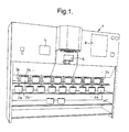
- Fig. 1 is a schematic perspective view illustrating an example of how an arrangement in a mixer according to the invention can be implemented.
- Fig. 2 illustrates, on a larger scale, an example of an operator panel which is used in the arrangement illustrated in Fig. 1.
- Fig. 3 is a schematic principle sketch illustrating a non-limiting embodiment of an arrangement according to the present invention.
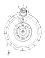
- Fig. 4 is a view as seen from above of a main member included in a special embodiment of a distribution means in an arrangement according to the present invention.
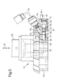
- Fig. 5 is a side view of the main member illustrated in Fig. 4.
- Figures 6A, 6B and 6C illustrate, on a larger scale, one of the valve sections included in the main member illustrated in Figures 4 and 5.
- Fig. 7 illustrates, on a larger scale, a view partly in section of a combined lid and piston illustrated in Fig. 3.
- Fig. 1 which schematically and perspectively is a view illustrating an example of how an arrangement in a mixer according to the invention can be implemented, the arrangement proper is stated by reference numeral 1.
- the present arrangement which is specifically developed in connection with the mixing of printing colours for graphics or offset-colour, but which can also be used for mixing other appropriate colours, comprises a plurality of colour containers 2a, 2b ... 2n, each of which containing a so-called base colour.
- the number of such colour containers 2a, 2b ... 2n can, of course, be varied within wide limits and an appropriate number in the embodiment according to Fig. 1, has been chosen as 17.
- Each of these 17 colour containers 2a, 2b ... 2n is connected to an individual output conduit 3a, 3b ...
- control means 4 which according to a preset programme, for example by means of a control panel 5, influences the mentioned distribution means to let through the desired quantity of base colour from preselected colour containers to a common mixing vessel 6, preferably on a scale basis.
- the operator can thus firstly chose the quantity of colour which is desired, for example a batch quantity of 50-200 g to 2500 g. Thereafter, the operator punches in the percentage part corresponding to the colour prescription, which can comprise for example five colours or more, the sum of said percentage parts summing up to 100%. Thereafter, the operator pushes on start and the arrangement according to the invention carries out the necessary operations so that the predetermined quantity of colour is taken out with the correct percentage part from the selected base colour containers for the collection thereof in a common mixing vessel 6 in accordance with the selected colour prescription.
- the mixture may be fine adjusted with quantities of colours of quantity range 0,2 g, or less, which involves that most of the practical colour prescriptions can be mixed very accurately both at the initial mixture and by repeating mixtures.
- Fig. 2 there is, on a larger scale, illustrated an example of how an operator panel 5 can be designed, especially for use in the arrangement which is schematically illustrated in Fig. 1. It is to be understood that together with the finished mixture in the mixing vessel 6 the control means 4 can print out the prescription as punched, which appropriately can be stored in the system, or be printed out as a delivery note together with the finished mixture.
- Fig. 3 there is depicted a schematic principle sketch giving an overview on how a non-limited embodiment of an arrangement according to the invention can be realized.
- a previously discussed valve carrying distribution means 10 comprising a plurality of valve sections 11a-11n, preferably arranged in a ring, above the common previously discussed mixing vessel 6 illustrated in Fig. 3.
- the distribution means 10 itself comprises for example 17 valve sections 11a-11n arranged in a ring, each valve section 11a-11n on the one side via appropriate inlet openings 13a-13n being connected to each individual of said mentioned outlet conduits 3a-3n extending from the respective colour container 2a-2n, and on the other side being adapted to appropriately recessed valve housings 14a-14n to hold regulating valve.
- valve 15 which can be held by respective valve housings 14a-14n is illustrated in Figures 4, 5 and 6, here generally designated by reference numeral 15, said figures 6A-6C illustrating the valve 15 in various operating positions, as this will be further discussed in the following.
- the distribution means 10 is substantially stationary provided, the latter encircling a valve control means which generally is designated by reference numeral 20, and which can be brought to selected position in relation to the individual valve section 11a-11n in order to contribute to a correct stroke length by opening/closing the respective valve 15 arranged therein, and then in accordance with the preprogrammed colour prescription.
- a valve control means which generally is designated by reference numeral 20, and which can be brought to selected position in relation to the individual valve section 11a-11n in order to contribute to a correct stroke length by opening/closing the respective valve 15 arranged therein, and then in accordance with the preprogrammed colour prescription.
- the valve control means 20 can appropriately be connected to a drive means 21, for example a pneumatic drive means, for thereby displacing the valve control means 20 to preselected positions, which preselected positions are controlled by the previously discussed control means 4, see Fig. 1.
- a drive means 21 for example a pneumatic drive means
- Fig. 3 and Fig. 5 the drive means 21 is symbolized by means of a triple arrow, which will indicate that the valve control means in an appropriate embodiment can be given appropriate lowering motions, as well as one or more appropriate raising movements, all of which being adapted to the remaining shape of the valve control means 20 itself, and the manner in which it communicates with the respective valves 15 in the respective valve housings 14a-14n.
- control means 4 cooperate with the valves 15 arranged in the distribution means 10 in such a way that when a colour prescription has been punched for each valve 15 in question or valve housing 14a-14n in question, there can be effected both crude dosage and/or fine dosage for achieving an accurate colour mixture.
- the individual valves 15 can be designed as this is illustrated in detail in Figures 4, 5 and 6A-6C, namely with at least two colour throughput openings, respectively a larger throughput opening 24 serving for crude dosage of the colour in question, as well as a smaller opening 25 serving for fine dosage of the colour in question.
- Examples of diameter of the openings can be 8 mm and 1,5 mm, respectively, but these dimensions can of course vary within wide limits.
- each valve 15 is provided in a respective valve housing, 14a-14n, each valve 15 comprising a substantially cylinder-shaped main member 16 having a first end portion 27 which is provided with a substantially inclined control surface 28 which is adapted to cooperate with an oppositely inclined surface 34 on the valve control means 20 in dependence of the position which the associated raising/lowering mechanism 21 has communicated to the valve control means 20.
- each valve 15 is in a valve housing 14a-14n which is connected to a pipe piece 40 for the supply of pressure air 41, which pressure air will be supplied via appropriate not illustrated individual hoses, which can have a common pressure air source or compressed air generator.
- FIG. 6A An example of a dosing course can be read from Figures 6A-6C, and in connection with Fig. 5, Fig. 6A illustrating a position in which both throughput openings or dosing openings 24 and 25 are in a retracted position, i.e. closed position, see also Fig. 5.
- the programme will order the drive means 21 of the valve control means 20, such that the valve control means 20 is lowered to an intermediate position which entails that the inclined surface 34 of the valve control means 20 will force the valve 15 to return into the valve housing 14a with a distance corresponding to the flushing of the lesser throughput opening 25 with the previously discussed outlet opening 30a which communicates with the corresponding supply hose 3a, the larger throughput opening 24 now being pulled into the valve housing 14a to a passive position, see especially Fig. 6B.
- the raising/lowering mechanism 21 will once more be activated, and then in such a manner that the valve control means 20 will be brought to its bottom lower position, which entails that the upper part of the inclined surface 34 will force the piston 15 all the way into the valve housing 14a, for complete closing of the valve, i.e. back to the starting point illustrated in Fig. 6A.
- the compressed air can be released and the used valve 15 will then remain in the valve housing 14a also after the retrieval of the valve control means 20 to its initial position, as this is illustrated in Fig.
- valve control means 20 for this to be lowered to its intermediate position, see especially Fig. 6B, before pressure air 41a is supplied via the supply piece 40 for influencing the piston 41 in the piston chamber 42, for thereby bringing the valve 15 to said fine dosage position.
- valve control means 20 Since the valve control means 20 has a lower part having conical portions 34, it is sufficient that the valve control means 20 is given a raising and lowering movement when the respective valves are to execute their dosage operations, i.e. turning of the valve control means 20 is avoided since the respective operation of the valves 15 is taken care of by separate compressed air supplies, see reference 40 in Figures 3, 4, 5 and 6A-6C.
- valve control means 20 in the form of a raisable/lowerable large piston having inclined surfaces 34, it is possible in a simple manner to perform maintenance and tests of the mixing arrangement itself.
- a test programme can be inserted for cleaning or control of the displaceability of the pistons or valves, namely the valves 15, in that the valve control means 20 is lowered to its intermediate position, i.e. the position for fine dosage, whereafter compressed air is supplied to all piston chambers 42 for advancing all valves 15 a little distance until the respective inclined surfaces 28 of the valves 15 will abut against the inclined surface 34 of the valve control means 20, see for example Fig.
- valve control means 20 in the course of a fraction of a second is lowered to its bottom position for retrieving all pistons, i.e. so quickly that colour does not leak out through the dosage openings. Thereafter the compressed air is shut off and the valve control means 20 is raised to its initial position, see Fig. 5.
- the distribution means 10 is appropriately arranged in a ring around the valve control means 20, and a further appropriate manner in which to design the distribution means 10 is as a tiltable arrangement, which will render inspection and maintenance easier.
- FIGS 5 and 6A-6C there is also illustrated O-rings 45 and 46 arranged in opposite circumferential recesses for appropriate sealing of the respective valves 15, respectively their valve bodies 16 in respective valve housings 14a-14n for the intermediate portion housing the graduated valve openings 24 and 25.
- a variant of an embodiment of distribution means can be reside in letting the valve control means being provided without bottom inclined surfaces, but only as a substantially cylindrical piston which can take only two positions, namely an upper position allowing full stroke of the respective valve for bringing the largest throughput opening to flush with the outlet opening above the mixing vessel, as well as a lower position allowing for the valve only to have a reduced stroke bringing the lesser throughput opening to flush with the respective outlet opening in the valve section in question.
- Such a variant will require a two-way pneumatic or hydraulic control of the valve which is arranged in the individual valve section or valve chamber, namely either a double supply of compressed air hoses to the piston chambers for the control of compressed air "behind” and "ahead of” said piston, or a special two-way valve with associated control means for controlling the same compressed air on the one or second side of the piston.
- a mixing course can then take place by the following steps:
- each of said colour containers here the colour container 2a, comprises a displaceable piston 50 operating as a lid and at its centre portion being provided with an outlet opening 51 which in turn via a hollow piston rod 52 is connected to the previously discussed outlet conduit 3a.
- the piston rod 52 is connected to a drive means which generally is designated by reference numeral 53, and which cooperates with said control means 4, for thereby being able to be influenced by means of a power cylinder 54 and via a lowering jib 55 to move the piston 50 down into or into the selected colour container 2a for pressing out therefrom an appropriate quantity of colour 56 from the colour container 2a and through the hollow piston rod 52 and corresponding outlet conduit 3a to the previously discussed distribution means 10, namely via the associated supply opening 13n to the respective valve housing 14n, and for via the outlet opening 30n of the valve housing in the form of a colour string 31 which ends up in the collection vessel 6.
- a drive means which generally is designated by reference numeral 53, and which cooperates with said control means 4, for thereby being able to be influenced by means of a power cylinder 54 and via a lowering jib 55 to move the piston 50 down into or into the selected colour container 2a for pressing out therefrom an appropriate quantity of colour 56 from the colour container 2a and through the hollow piston rod 52 and
- the piston rod 52 can further be provided with an engaging mechanism 57 which will be effective when the corresponding colour container 2a is to deliver a certain quantity of colour to the distribution means 10, which entails that the lowering jib 55 will serve only the piston rod 52 and associated piston 50 for the selected colour container 2a, whereas the remaining colour containers remain non-influenced.
- the same mechanism 57 may be effective when the piston 50 has been guided all the way to the bottom of the respective colour container 2a, which indicates an empty colour container 2a, such that the piston 50 thereafter can be guided all the way out of the empty box for replacement respectively filling up of the same.
- the piston 50 In order to secure that the piston 50 will empty the box 2a completely of colour, even if the box 2a is provided with inclined, upwardly extending walls 2aa, the piston 50 is around its circumference appropriately provided with a flexible gasket 50a having such dimensions and being of such a material that all the time there will be executed a sealed pressing out of colour 56, which is also illustrated, on a larger scale, in Fig. 7.
- the quantity of colour 32 which has been collected in the collecting vessel 6, is subjected to control weighing by means of one or more weighing cells 60 which appropriately are positioned between the mixing vessel 6 and a displaceable rack 61. It is to be understood that this control weighing can be effected in cooperation with said control means 4, based on the out-feeding string of colour 31 by means of an adaptive adjustment or lag adaption of expected outfeed of colour quantity. This adaptive adjustment or lag adaption can be based on the outfeed of colour string weight and/or time for pressing colour through the associated valve, respective valve opening.
- the distance between the mixing vessel bottom 6a or colour surface 32a of already supplied colour 32 can be regulated such that the colour string 31 which is fed out through the valve 15, will have an approximately equal extension when hitting the mixing vessel bottom 6a or the colour surface 32a.
- Said control means 4 can thus after signal from the weighing cells 60 accomplish an accurately monitored mixing operation, said control means both compensating for tara weight and calculated lag of colour. Said control means 4 control all movements, inter alia the individual valves, such that a larger quantity of colour will pass through the large valve opening, whereas finishing fine dosage takes place through a lesser valve opening.
- valve sections can be varied within wide limits, depending on the practical number of base colour including boxes in question. Further, it is to be understood that the output of colour from the individual base colour boxes can take place by means of other drive means than piston mechanisms, depending on the viscosity of the colour in question. In connection with offset-colour the viscosity can correspond to the consistency of vaseline or grease, but in connection with finely-fluid colours, there may be contemplated for example supply of colour by gravitation, possibly in combination with a pumping supply through appropriate conduits and valves.
Landscapes
- Chemical & Material Sciences (AREA)
- Chemical Kinetics & Catalysis (AREA)
- Processing And Handling Of Plastics And Other Materials For Molding In General (AREA)
- Accessories For Mixers (AREA)
- Paints Or Removers (AREA)
- Nozzles (AREA)
- Screen Printers (AREA)
Claims (15)
- Anordnung in einem Mischer (1), um insbesondere Druckfarbe zu mischen, wobei die Anordnung umfasst:dadurch gekennzeichnet, dass die Ventile tragende Verteilungseinrichtung (10) im Wesentlichen stationär angeordnet ist, und eine gemeinsame Ventilsteuerungseinrichtung (20) umgibt, die in eine Stellung vor dem einzelnen Ventilgehäuse (14a-14n) gebracht werden kann, um zu dem Öffnen/Schließen des entsprechenden Ventils (15) beizutragen, beziehungsweise die Hublänge des einzelnen Ventils zu entscheiden,eine Vielzahl von Farbbehältern (2a-2n), von denen jeder eine Grundfarbe enthält und an Auslassleitungen (3a-3n) angeschlossen ist, durch welche die Grundfarbe zugeführt werden kann, zueiner Ventile tragenden Verteilungseinrichtung (10), die mit den einzelnen Farbbehältern (2a-2n) über die Auslassleitungen (3a-3n)in Verbindung gebracht werden kann,und eine Steuerungseinrichtung (4), die gemäß einem voreingestellten Programm die verteilungseinrichtung (10) beeinflusst, um eine gewünschte Menge von Basisfarbe, vorzugsweise auf einer Gewichtsbasis, aus vorgewählten Farbbehältern (2a-2n) zu einem gemeinsames Mischgefäß (6) durchzulassen,
- Anordnung nach Anspruch 1 dadurch gekennzeichnet, dass die ventiltragende Verteilungseinrichtung (10) eine Ventilsteuerungseinrichtung (20) umgibt, die an eine Antriebseinrichtung (21) angeschlossen ist, zum Beispiel eine hydraulische oder pneumatische Einheit, um die Ventilsteuerungseinrichtung (20) auf vorgewählte Stellungen anzuheben/abzusenken, wobei die unterschiedlichen Stellungen der Ventilsteuerungseinrichtung (20) die Hublänge des Regulierventils (15) und möglicherweise die geschlossene Stellung oder abgestuft geöffnete Stellungen des Ventils bestimmt.
- Anordnung nach Anspruch 1 oder 2 dadurch gekennzeichnet, dass die Ventil tragende Verteilungseinrichtung (10) eine Vielzahl von Ventilgehäusen (14a-14n) umfasst, die vorzugsweise in einem Ring (Fig. 3, Fig. 4) oberhalb des Mischgefäßes (6)angeordnet sind, wobei jedes Ventilgehäuse (14a-14n) auf der einen Seite (13a-13n) an eine einzelne Auslassleitung (3a-3n) von einem Farbgehäuse (2a-2n) angeschlossen ist, und auf der anderen Seite angepasst ist, um ein regelndes Ventil (15) zu halten.
- Anordnung nach einem der vorangegangenen Ansprüche dadurch gekennzeichnet, dass jedes der regelnden Ventile (15) in einem einzelnen Ventilgehäuse (14a-14n) angeordnet ist, welche einzeln durch geeignete Zuführungseinrichtungen (40) für individuelle Druckzufuhr zu den einzelnen Ventilgehäusen (14a-14n) an eine Druckluftzufuhr (41a), angeschlossen ist.
- Anordnung nach einem der vorangegangenen Ansprüche dadurch gekennzeichnet, dass die Steuerungsseinrichtung (4) mit Ventilen (15) in der Verteilungseinrichtung (10) zusammenarbeitet, die mindestens zwei Farbdurchsatzöffnungen (24, 25) mit unteschiedlichen Abmessungen umfassen, wobei eine oder mehrere der größeren Durchsatzöffnungen (24) der Grobdosierung der betreffenden Farbe dienen, während eine oder mehrere der kleineren Öffnungen (25) der Feindosierung der betreffenden Farbe dienen.
- Anordnung nach einem der vorangegangenen Ansprüche dadurch gekennzeichnet, dass die Verteilungseinrichtung (10) eine Ventilsteuerungseinrichtung (20) umgibt, die an ihrem unteren Abschnitt die Form eines Konus annimmt, d.h. mindestens eine geneigte Fläche (34) beinhaltet, welche mit einer entgegegesetzt geneigten Fläche (28) eines abgestuften Ventils (15) zusammenarbeiten kann.
- , Anordnung nach einem der vorangegangenen Ansprüche dadurch gekennzeichnet, dass jedes Ventilgehäuse (14a-14n) einen Kolben (41) umfasst, der mit einer Druckluftquelle (40) in Verbindung steht, und dass jedes Ventil (15) ein im Wesentlichen zylindrisches Hauptelement (16) mit einem freien Endabschnitt (27) besitzt, der mit einer geneigten Führungsfläche (28) versehen ist, die an einer entsprechenden geneigten Fläche (34) der Ventilsteuerungseinrichtung anliegt, wobei eine im Wesentlichen senkrechten Verlagerung der Ventilsteuerungseinrichtung (20) in die eine Richtung eine große Hublänge des Ventils (15) verursacht, wenn letzteres Druckluft ausgesetzt wird, während eine weitere Absenkung der Ventilsteuerungseinrichtungs (20) eine Verlagerung des Ventils (15) in das Ventilgehäuse (14a) zurück verursacht, um die zweite offene Position (25) einzustellen.
- Anordnung nach einem der Ansprüche 1-4 dadurch gekennzeichnet, dass die Verteilungseinrichtung eine Ventilsteuerungseinrichtung umgibt, die im Wesentlichen zylindrisch geformt ist, und die angepasst ist, eine obere Stellung einzunehmen, die eine volle Hublänge zur Grobdosierung durch ein oder mehrere Ventile erlaubt, sowie eine abgesenkte Stellung, die die Hublänge zur Feindosierung durch eine oder mehrere Ventile vermindert.
- Anordnung nach einem der vorangegangenen Ansprüche dadurch gekennzeichnet, dass die Verteilungseinrichtung (10) eine Vielzahl von Ventilabschnitten (11a-11n) umfasst, die vorzugsweise auf einer neigbaren Einrichtung zur vereinfachten Prüfung und Reinigung der Verteilungseinrichtung angeordnet sind.
- Anordnung nach einem der vorangegangenen Ansprüche dadurch gekennzeichnet, dass die gewünschte vorgewählte Farbmenge (31), die durch die Verteilungseinrichtung (10) gelassen wird, einer Kontrollwägung mittels eines oder mehrerer Wägeelemente (60) unterzogen wird, die das Mischgefäß (12) tragen, insbesondere durch Einrichtungen mit anpassungsfähiger Justierung oder Zeitabstandsanpassung der erwarteten Farbenmenge, die ausgepresst werden soll, basierend auf dem Gewicht des ausgepressten Farbstrangs und/oder der Zeit zum Pressen der Farbe durch das zugehörige Ventil (15).
- Anordnung nach einem der vorangegangenen Ansprüche dadurch gekennzeichnet, dass das Wägeelement (60) für das Mischgefäß (12) auf einer verlagerbaren Auflage (61) angeordnet ist, die vorzugsweise Anhebungs-/Absenkungseinrichtungen umfasst, um die Entfernung zwischen dem Boden des Mischgefäßes (12a) oder der Farboberfläche (32a) zu ihr angemessen zu ändern, derart, dass der durch ein Ventil (15) ausgepresste Farbstrang (31) eine annähernd gleiche Länge aufweist, wenn er den Boden des Mischgefäßes (12a) oder die Farboberfläche (32a) trifft.
- Anordnung nach einem der vorangegangenen Ansprüche dadurch gekennzeichnet, dass jeder der Farbbehälter (2a-2n) einen verschieblichen Kolben (50) umfasst, der als Deckel dient und in seinem mittleren Abschnitt mit einer Auslassöffnung (51) versehen ist, die an die Auslassleitung (3a) angeschlossen ist, wobei die Auslassleitung (3a) in dem Bereich des Deckels (50) als hohle Kolbenstange (52) ausgebildet ist.
- Anordnung nach Anspruch 12 dadurch gekennzeichnet, dass die Kolbenstange (52) mit einer Antriebseinrichtung (53) versehen ist, die mit der Steuerungseinrichtung (2) zusammenarbeitet, und die beeinflusst wird, um den Kolben (50) runter hinein oder in den gewählten Farbbehälter (2a) zu verlagern, um daraus eine angemessene Farbmenge durch die Kolbenstange (52) und die zugehörige Auslassleitung (3a) zu der Verteilungseinrichtung (10) auszupressen.
- Anordnung nach Anspruch 12 oder 13 dadurch gekennzeichnet, dass die Kolbenstange (52) mit einem Mechanismus(53) vorgesehen ist, der reagiert, wenn der Kolben (50) vollständig in den Farbbehälter (2a) eingebracht ist, um dadurch einen leeren Farbbehälter und die Notwendigkeit zum Wechsel/Auffüllen desselben anzuzeigen.
- Anordnung nach Anspruch 12, 13 oder 14 dadurch gekennzeichnet, dass um den Umfang des Kolbens (50) eine flexible Dichtungseinrichtung (50a) angeordnet ist, die mit solchen Abmessungen gestaltet und aus einem solchen Material gefertigt ist, dass der Kolben (50) dichtend gegen die geneigten Behälterwände (2aa) drückt.
Priority Applications (1)
| Application Number | Priority Date | Filing Date | Title |
|---|---|---|---|
| DE29624382U DE29624382U1 (de) | 1995-03-01 | 1996-02-27 | Anordnung in einem Mischer, insbesondere zum Mischen von Druckfarbe |
Applications Claiming Priority (5)
| Application Number | Priority Date | Filing Date | Title |
|---|---|---|---|
| NO950797A NO950797L (no) | 1995-03-01 | 1995-03-01 | Anordning ved blandemaskin, spesielt for blanding av trykk-farge |
| NO950797 | 1995-03-01 | ||
| NO954406 | 1995-11-03 | ||
| NO954406A NO954406L (no) | 1995-03-01 | 1995-11-03 | Anordning ved blandemaskin, spesielt for blanding av trykk-farge |
| PCT/NO1996/000045 WO1996026889A1 (en) | 1995-03-01 | 1996-02-27 | Arrangement in a mixer, especially for mixing printing colour |
Publications (2)
| Publication Number | Publication Date |
|---|---|
| EP0809603A1 EP0809603A1 (de) | 1997-12-03 |
| EP0809603B1 true EP0809603B1 (de) | 2002-11-13 |
Family
ID=26648560
Family Applications (1)
| Application Number | Title | Priority Date | Filing Date |
|---|---|---|---|
| EP96906109A Expired - Lifetime EP0809603B1 (de) | 1995-03-01 | 1996-02-27 | Anordnung in einem mischer, insbesondere zum mischen von druckfarben |
Country Status (9)
| Country | Link |
|---|---|
| US (1) | US6000837A (de) |
| EP (1) | EP0809603B1 (de) |
| CN (1) | CN1070388C (de) |
| AT (1) | ATE227691T1 (de) |
| AU (1) | AU685355B2 (de) |
| CA (1) | CA2212299C (de) |
| DE (1) | DE69624793T2 (de) |
| NO (1) | NO954406L (de) |
| WO (1) | WO1996026889A1 (de) |
Families Citing this family (14)
| Publication number | Priority date | Publication date | Assignee | Title |
|---|---|---|---|---|
| NL1006911C2 (nl) * | 1997-09-02 | 1999-03-04 | Gerritse Beheer Bv | Inrichting voor het gedoseerd afgeven van een aantal verschillende vloeibare of pasteuze massa's. |
| US7339000B1 (en) | 1998-12-23 | 2008-03-04 | Coatings Management Systems Inc. | Method and apparatus for producing an aqueous paint composition from a plurality of premixed compositions |
| ATE326205T1 (de) | 2000-01-31 | 2006-06-15 | Engelhard Corp | Tensidfreietopische zusammensetzungen und verfahren zur schnelle herstellung davon |
| DE10034890A1 (de) * | 2000-07-18 | 2002-01-31 | Basf Ag | Vorrichtung und Verfahren zur automatisierten Formulierung und automatisierten Charakterisierung von Dispersionen |
| DE102004040020A1 (de) * | 2004-08-18 | 2006-03-02 | Werner & Mertz Gmbh | Apparat und Verfahren zur Herstellung von Reinigungsmitteln |
| DE102006006288A1 (de) * | 2006-02-10 | 2007-08-23 | Hte Ag The High Throughput Experimentation Company | Dosierstation und Verfahren zur Dosierung hochviskoser Flüssigkeiten |
| US7698021B2 (en) * | 2007-06-01 | 2010-04-13 | Microblend Technologies, Inc. | Method and apparatus for producing paint |
| US10549247B2 (en) * | 2010-03-22 | 2020-02-04 | Eric D. Schwartz | Portable custom nail polish creator |
| NL2006972C2 (en) | 2011-06-21 | 2012-12-28 | F Ll Process S A | Colorant fluid dispensing system. |
| US9604186B1 (en) * | 2012-05-01 | 2017-03-28 | Dow Agrosciences Llc | Automated multichannel media dispenser |
| TWI556874B (zh) * | 2014-02-26 | 2016-11-11 | 辛耘企業股份有限公司 | 中空緩衝驅動裝置 |
| TWI599406B (zh) * | 2014-02-26 | 2017-09-21 | 辛耘企業股份有限公司 | 中空緩衝驅動裝置 |
| US20160082403A1 (en) * | 2014-09-24 | 2016-03-24 | Younes Ounzar | Multi-color fluid dispenser apparatus |
| US10441929B2 (en) * | 2016-11-01 | 2019-10-15 | Walmart Apollo, Llc | Automated paint mixing and verification system and methods |
Family Cites Families (17)
| Publication number | Priority date | Publication date | Assignee | Title |
|---|---|---|---|---|
| DE3000949A1 (de) * | 1979-01-26 | 1980-08-28 | Bi M Insutrument Co | Einrichtung und verfahren zur erzeugung eines eichgasgemisches sowie ventilanordnung hierfuer |
| US4302113A (en) * | 1980-04-11 | 1981-11-24 | Eastman Kodak Company | Method and apparatus for admixing photographic processing compositions |
| DE3201221A1 (de) * | 1982-01-16 | 1983-07-28 | Walter 4600 Dortmund Ribic | Station zum anmischen insbesondere von farben und dergleichen |
| DE3419485A1 (de) * | 1984-05-25 | 1985-11-28 | FECO-Industrieanlagenbau GmbH, 2000 Hamburg | Dosiervorrichtung |
| DE3431112A1 (de) * | 1984-08-24 | 1986-03-06 | Spühl AG, St. Gallen | Mischkopf zur reaktiven mischung von kunststoff-komponenten |
| IT1182287B (it) * | 1984-09-26 | 1987-10-05 | Montelera Spa | Impianto per la produzione estemporanea di inchiostri da stampa liquidi o semiliquidi di qualita e colori differenti |
| GB2193581B (en) * | 1986-07-03 | 1990-09-19 | Francis Packaging Ltd | Fluid dispensing apparatus and method of operation thereof |
| DE3729318C2 (de) * | 1987-09-02 | 1994-08-11 | Mader Gmbh | Hubvorrichtung |
| US4944599A (en) * | 1987-11-10 | 1990-07-31 | Krauss-Maffei A.G. | Impingement mixing device with pressure controlled nozzle adjustment |
| US5020917A (en) * | 1987-12-23 | 1991-06-04 | Chemstation International, Inc. | Cleaning solution mixing and metering system |
| US4871262A (en) * | 1988-02-04 | 1989-10-03 | Hydrocosmetics, Inc. | Cosmetic dispensing system |
| JPH01278320A (ja) * | 1988-04-30 | 1989-11-08 | Toyoda Gosei Co Ltd | ミキシングヘッド |
| US4924900A (en) * | 1988-08-02 | 1990-05-15 | Systems Specialties | Adjustable ratio mixing valve |
| US5163010A (en) * | 1990-02-22 | 1992-11-10 | Revlon Consumer Products Corporation | Formulating device for cosmetically functional cosmetic products |
| US5350233A (en) * | 1992-09-22 | 1994-09-27 | Reagent Chemical & Research, Inc. | Mixing apparatus and method for forming a blended composite material from a plurality of components |
| DE4322442A1 (de) * | 1993-07-06 | 1995-01-12 | Reinhard Kissler Gmbh Anlagenb | Verfahren und Vorrichtung zum Mischen von Flüssigkeiten, insbesondere Farben |
| US5375634A (en) * | 1993-10-07 | 1994-12-27 | Graco Inc. | Variable mass flow rate fluid dispensing control |
-
1995
- 1995-11-03 NO NO954406A patent/NO954406L/no not_active Application Discontinuation
-
1996
- 1996-02-27 AT AT96906109T patent/ATE227691T1/de not_active IP Right Cessation
- 1996-02-27 DE DE69624793T patent/DE69624793T2/de not_active Expired - Fee Related
- 1996-02-27 US US08/894,891 patent/US6000837A/en not_active Expired - Fee Related
- 1996-02-27 CA CA002212299A patent/CA2212299C/en not_active Expired - Fee Related
- 1996-02-27 WO PCT/NO1996/000045 patent/WO1996026889A1/en not_active Ceased
- 1996-02-27 CN CN96192267A patent/CN1070388C/zh not_active Expired - Fee Related
- 1996-02-27 EP EP96906109A patent/EP0809603B1/de not_active Expired - Lifetime
- 1996-02-27 AU AU49588/96A patent/AU685355B2/en not_active Ceased
Also Published As
| Publication number | Publication date |
|---|---|
| NO954406L (no) | 1996-09-02 |
| AU4958896A (en) | 1996-09-18 |
| CN1177335A (zh) | 1998-03-25 |
| CA2212299A1 (en) | 1996-09-06 |
| DE69624793D1 (de) | 2002-12-19 |
| AU685355B2 (en) | 1998-01-15 |
| ATE227691T1 (de) | 2002-11-15 |
| CN1070388C (zh) | 2001-09-05 |
| DE69624793T2 (de) | 2003-08-14 |
| EP0809603A1 (de) | 1997-12-03 |
| NO954406D0 (no) | 1995-11-03 |
| US6000837A (en) | 1999-12-14 |
| CA2212299C (en) | 2005-01-25 |
| WO1996026889A1 (en) | 1996-09-06 |
Similar Documents
| Publication | Publication Date | Title |
|---|---|---|
| US6000837A (en) | Arrangement in a mixer, especially for mixing printing color | |
| US5584326A (en) | Compact apparatus for the storage, delivery and mixing of fluid substances | |
| US4288230A (en) | Method and a device for the production of a solid-forming or foam-forming flowable reaction mixture | |
| US20030010398A1 (en) | Flow meter type liquid filling apparatus | |
| EP0946274B1 (de) | Dosier- und abtönanlage | |
| CN101273249A (zh) | 用于聚氨酯设备的添加物定量装置 | |
| EP0944814B1 (de) | Verfahren und vorrichtung zur bestimmung des volumens eines gases und/oder des materialvolumens einer probe aus feststoff- und/oder flüssigstoff-material | |
| US3915437A (en) | Mixing apparatus | |
| US6662975B1 (en) | Apparatus and a method for metering liquids | |
| US4196852A (en) | Compressed air test sample preparing and spraying apparatus | |
| US5947141A (en) | Foam inductor system and method of using same | |
| JP3267529B2 (ja) | 塗料混合装置および方法 | |
| US2742914A (en) | Method of and apparatus for continuously maintaining uniform the composition of a composite liquid | |
| US6230761B1 (en) | Injection system | |
| KR900701491A (ko) | 폴리올에 유동 가능한 첨가물들을 혼합하는 방법 및 이 방법을 실시하기 위한 장치 | |
| CN103055735B (zh) | 含果肉的饮料和含纤维的饮料用的混合器 | |
| KR100320526B1 (ko) | 도징시스템 | |
| DE202014100750U1 (de) | Vorrichtung zur gesteuerten Entnahme von flüssigen Materialien aus mehreren Vorlagebehältern | |
| CN209383378U (zh) | 一种用于锂电池电极涂布的陶瓷供料系统 | |
| GB2073035A (en) | Seed dressing equipment for a sowing machine | |
| CN119258912B (zh) | 一种定时加料的医药中间体生成设备 | |
| DE1783080C (de) | Pneumatisch betriebene Dosiervorrichtung für flüssige Zuschlagstoffe bei einem kontinuierlich arbeitenden Mischapparat für Gießereisand | |
| CN214563848U (zh) | 一种全自动供墨设备的进料系统 | |
| DE29624382U1 (de) | Anordnung in einem Mischer, insbesondere zum Mischen von Druckfarbe | |
| JPH0392318A (ja) | 複数液の反応射出装置 |
Legal Events
| Date | Code | Title | Description |
|---|---|---|---|
| PUAI | Public reference made under article 153(3) epc to a published international application that has entered the european phase |
Free format text: ORIGINAL CODE: 0009012 |
|
| 17P | Request for examination filed |
Effective date: 19970728 |
|
| AK | Designated contracting states |
Kind code of ref document: A1 Designated state(s): AT BE CH DE DK ES FR GB IT LI NL PT SE |
|
| GRAG | Despatch of communication of intention to grant |
Free format text: ORIGINAL CODE: EPIDOS AGRA |
|
| 17Q | First examination report despatched |
Effective date: 20020204 |
|
| GRAG | Despatch of communication of intention to grant |
Free format text: ORIGINAL CODE: EPIDOS AGRA |
|
| GRAH | Despatch of communication of intention to grant a patent |
Free format text: ORIGINAL CODE: EPIDOS IGRA |
|
| GRAG | Despatch of communication of intention to grant |
Free format text: ORIGINAL CODE: EPIDOS AGRA |
|
| GRAH | Despatch of communication of intention to grant a patent |
Free format text: ORIGINAL CODE: EPIDOS IGRA |
|
| RAP3 | Party data changed (applicant data changed or rights of an application transferred) |
Owner name: BJELLAND, MORTEN Owner name: RANDSBORG, TORBJOERN |
|
| RIN1 | Information on inventor provided before grant (corrected) |
Inventor name: BJELLAND, MORTEN Inventor name: RANDSBORG, TORBJOERN |
|
| GRAH | Despatch of communication of intention to grant a patent |
Free format text: ORIGINAL CODE: EPIDOS IGRA |
|
| GRAA | (expected) grant |
Free format text: ORIGINAL CODE: 0009210 |
|
| AK | Designated contracting states |
Kind code of ref document: B1 Designated state(s): AT BE CH DE DK ES FR GB IT LI NL PT SE |
|
| PG25 | Lapsed in a contracting state [announced via postgrant information from national office to epo] |
Ref country code: NL Free format text: LAPSE BECAUSE OF FAILURE TO SUBMIT A TRANSLATION OF THE DESCRIPTION OR TO PAY THE FEE WITHIN THE PRESCRIBED TIME-LIMIT Effective date: 20021113 Ref country code: LI Free format text: LAPSE BECAUSE OF FAILURE TO SUBMIT A TRANSLATION OF THE DESCRIPTION OR TO PAY THE FEE WITHIN THE PRESCRIBED TIME-LIMIT Effective date: 20021113 Ref country code: IT Free format text: LAPSE BECAUSE OF FAILURE TO SUBMIT A TRANSLATION OF THE DESCRIPTION OR TO PAY THE FEE WITHIN THE PRESCRIBED TIME-LIMIT;WARNING: LAPSES OF ITALIAN PATENTS WITH EFFECTIVE DATE BEFORE 2007 MAY HAVE OCCURRED AT ANY TIME BEFORE 2007. THE CORRECT EFFECTIVE DATE MAY BE DIFFERENT FROM THE ONE RECORDED. Effective date: 20021113 Ref country code: CH Free format text: LAPSE BECAUSE OF FAILURE TO SUBMIT A TRANSLATION OF THE DESCRIPTION OR TO PAY THE FEE WITHIN THE PRESCRIBED TIME-LIMIT Effective date: 20021113 Ref country code: BE Free format text: LAPSE BECAUSE OF FAILURE TO SUBMIT A TRANSLATION OF THE DESCRIPTION OR TO PAY THE FEE WITHIN THE PRESCRIBED TIME-LIMIT Effective date: 20021113 Ref country code: AT Free format text: LAPSE BECAUSE OF FAILURE TO SUBMIT A TRANSLATION OF THE DESCRIPTION OR TO PAY THE FEE WITHIN THE PRESCRIBED TIME-LIMIT Effective date: 20021113 |
|
| REF | Corresponds to: |
Ref document number: 227691 Country of ref document: AT Date of ref document: 20021115 Kind code of ref document: T |
|
| REG | Reference to a national code |
Ref country code: GB Ref legal event code: FG4D |
|
| REG | Reference to a national code |
Ref country code: CH Ref legal event code: EP |
|
| REF | Corresponds to: |
Ref document number: 69624793 Country of ref document: DE Date of ref document: 20021219 |
|
| PG25 | Lapsed in a contracting state [announced via postgrant information from national office to epo] |
Ref country code: SE Free format text: LAPSE BECAUSE OF FAILURE TO SUBMIT A TRANSLATION OF THE DESCRIPTION OR TO PAY THE FEE WITHIN THE PRESCRIBED TIME-LIMIT Effective date: 20030213 Ref country code: PT Free format text: LAPSE BECAUSE OF FAILURE TO SUBMIT A TRANSLATION OF THE DESCRIPTION OR TO PAY THE FEE WITHIN THE PRESCRIBED TIME-LIMIT Effective date: 20030213 Ref country code: DK Free format text: LAPSE BECAUSE OF FAILURE TO SUBMIT A TRANSLATION OF THE DESCRIPTION OR TO PAY THE FEE WITHIN THE PRESCRIBED TIME-LIMIT Effective date: 20030213 |
|
| NLV1 | Nl: lapsed or annulled due to failure to fulfill the requirements of art. 29p and 29m of the patents act | ||
| ET | Fr: translation filed | ||
| PG25 | Lapsed in a contracting state [announced via postgrant information from national office to epo] |
Ref country code: ES Free format text: LAPSE BECAUSE OF FAILURE TO SUBMIT A TRANSLATION OF THE DESCRIPTION OR TO PAY THE FEE WITHIN THE PRESCRIBED TIME-LIMIT Effective date: 20030529 |
|
| REG | Reference to a national code |
Ref country code: CH Ref legal event code: PL |
|
| PLBE | No opposition filed within time limit |
Free format text: ORIGINAL CODE: 0009261 |
|
| STAA | Information on the status of an ep patent application or granted ep patent |
Free format text: STATUS: NO OPPOSITION FILED WITHIN TIME LIMIT |
|
| 26N | No opposition filed |
Effective date: 20030814 |
|
| PGFP | Annual fee paid to national office [announced via postgrant information from national office to epo] |
Ref country code: GB Payment date: 20080118 Year of fee payment: 13 |
|
| PGFP | Annual fee paid to national office [announced via postgrant information from national office to epo] |
Ref country code: FR Payment date: 20080108 Year of fee payment: 13 Ref country code: DE Payment date: 20080429 Year of fee payment: 13 |
|
| GBPC | Gb: european patent ceased through non-payment of renewal fee |
Effective date: 20090227 |
|
| REG | Reference to a national code |
Ref country code: FR Ref legal event code: ST Effective date: 20091030 |
|
| PG25 | Lapsed in a contracting state [announced via postgrant information from national office to epo] |
Ref country code: DE Free format text: LAPSE BECAUSE OF NON-PAYMENT OF DUE FEES Effective date: 20090901 |
|
| PG25 | Lapsed in a contracting state [announced via postgrant information from national office to epo] |
Ref country code: GB Free format text: LAPSE BECAUSE OF NON-PAYMENT OF DUE FEES Effective date: 20090227 Ref country code: FR Free format text: LAPSE BECAUSE OF NON-PAYMENT OF DUE FEES Effective date: 20090302 |