EP0809749B1 - Moteur a pistons alternatifs comportant des cylindres adjacents dans le sens du vilebrequin dans un carter - Google Patents
Moteur a pistons alternatifs comportant des cylindres adjacents dans le sens du vilebrequin dans un carter Download PDFInfo
- Publication number
- EP0809749B1 EP0809749B1 EP96904775A EP96904775A EP0809749B1 EP 0809749 B1 EP0809749 B1 EP 0809749B1 EP 96904775 A EP96904775 A EP 96904775A EP 96904775 A EP96904775 A EP 96904775A EP 0809749 B1 EP0809749 B1 EP 0809749B1
- Authority
- EP
- European Patent Office
- Prior art keywords
- guide
- eccentric
- reciprocating
- disposed
- piston rods
- Prior art date
- Legal status (The legal status is an assumption and is not a legal conclusion. Google has not performed a legal analysis and makes no representation as to the accuracy of the status listed.)
- Expired - Lifetime
Links
- 238000002485 combustion reaction Methods 0.000 claims description 4
- 238000005096 rolling process Methods 0.000 claims description 4
- 230000003068 static effect Effects 0.000 claims description 2
- 230000008878 coupling Effects 0.000 description 9
- 238000010168 coupling process Methods 0.000 description 9
- 238000005859 coupling reaction Methods 0.000 description 9
- 238000004519 manufacturing process Methods 0.000 description 3
- 210000001061 forehead Anatomy 0.000 description 2
- 238000005461 lubrication Methods 0.000 description 2
- 230000005540 biological transmission Effects 0.000 description 1
- 230000015572 biosynthetic process Effects 0.000 description 1
- 238000010276 construction Methods 0.000 description 1
- 230000008030 elimination Effects 0.000 description 1
- 238000003379 elimination reaction Methods 0.000 description 1
- 239000004575 stone Substances 0.000 description 1
Images

Classifications
-
- F—MECHANICAL ENGINEERING; LIGHTING; HEATING; WEAPONS; BLASTING
- F01—MACHINES OR ENGINES IN GENERAL; ENGINE PLANTS IN GENERAL; STEAM ENGINES
- F01B—MACHINES OR ENGINES, IN GENERAL OR OF POSITIVE-DISPLACEMENT TYPE, e.g. STEAM ENGINES
- F01B9/00—Reciprocating-piston machines or engines characterised by connections between pistons and main shafts, not specific to groups F01B1/00 - F01B7/00
- F01B9/02—Reciprocating-piston machines or engines characterised by connections between pistons and main shafts, not specific to groups F01B1/00 - F01B7/00 with crankshaft
- F01B9/026—Rigid connections between piston and rod; Oscillating pistons
-
- F—MECHANICAL ENGINEERING; LIGHTING; HEATING; WEAPONS; BLASTING
- F02—COMBUSTION ENGINES; HOT-GAS OR COMBUSTION-PRODUCT ENGINE PLANTS
- F02B—INTERNAL-COMBUSTION PISTON ENGINES; COMBUSTION ENGINES IN GENERAL
- F02B75/00—Other engines
- F02B75/16—Engines characterised by number of cylinders, e.g. single-cylinder engines
- F02B75/18—Multi-cylinder engines
- F02B75/24—Multi-cylinder engines with cylinders arranged oppositely relative to main shaft and of "flat" type
- F02B75/246—Multi-cylinder engines with cylinders arranged oppositely relative to main shaft and of "flat" type with only one crankshaft of the "pancake" type, e.g. pairs of connecting rods attached to common crankshaft bearing
Definitions
- the invention is based on the preamble of claim 1 of GB-A 1,060,372.
- This document shows and describes an embodiment of a reciprocating piston machine with diametrically arranged pairs of cylinders, the parallel axes of which Cut the crankshaft axis of rotation orthogonally.
- This generic reciprocating machine is an internal combustion engine combined with a piston compressor.
- This known machine comprises a jack with a hypocycloid Straight guidance, which combined with a crankshaft and with each other rotatably connected eccentric includes.
- Both opposed in diametrical cylinders Piston rods connecting pistons stand out together with one two-part, tubular stroke eccentric in drive connection, in the a guide eccentric with one end of the machine housing on both ends rectilinearly guided guide element is arranged.
- Another disadvantage is the complex and complex structure of this jack with hypocycloidal straight line.
- DE-PS 271 755 shows and describes an embodiment of an internal combustion engine with reciprocating pistons in diametrically arranged cylinder pairs, whose parallel axes run in a transverse plane to the crankshaft axis of rotation. This The arrangement allows the for a jack with hypocycloidal straight guidance Connection of the parallel piston rods to a single guide ring stroke eccentric arranged in the middle between pinions of pairs of cardan circles.
- a hypocycloid reciprocating piston machine in the plane of the crankshaft axis of rotation in the direction of the crankshaft has adjacent pairs of cylinders, between the push rods as a hypocycloid straight line, another orthogonally arranged A pair of cylinders is provided.
- this pair of cylinders they serve in others Cylinders of the reciprocating piston machine oscillating pistons as guide elements, so that with this crosswise arrangement of pairs of cylinders a disadvantage large-scale internal combustion engine results.
- the invention is based, for a generic piston engine the task the greatest possible simplification, in particular of the lifting engine depict hypocycloidal straightness, which is also a compact design allowed at a relatively low weight.
- Piston rods for pistons in a pair of cylinders or for pistons in two The invention offers diametrically arranged cylinder pairs (4-cylinder flat engine) in an advantageous manner in addition to a space-saving arrangement of a part of the Mainly hypocycloidal straight line between the piston rods a particularly simple structure. This can be done with minimal effort of a single, interacting with guide surfaces provided on the housing Guide element reached, with which a minimum of straight guide components and guide surfaces is achieved.
- a reciprocating piston machine are diametrically arranged pairs of cylinders opposite reciprocating pistons via piston rods connected connected in the same direction, being on a crank pin of the crankshaft in the middle between the piston rods with the single guide element hypocycloidal straight guide interacting guide eccentric rotatable is arranged, which is arranged on both sides adjacent to the crank pin and stroke eccentrics that engage in the piston rods so as to rotate the straight guide is in a rotationally fixed connection.
- This 3-disc eccentric combination according to the invention points to that from the above DE-PS 271 755 known eccentric double pinion combination due to the elimination of the gears on a simpler design, which also the transmission high piston forces with safe hydrodynamic lubrication guaranteed.
- This arrangement according to the invention advantageously reduces the Free crank pin length for two pairs of pistons in synchronism to a minimum, which results from the cylinder distance plus twice the half piston rod strength results.
- the guiding element is the hypocycloid Straight guidance a Wattscher already proposed in DE-A 41 08 311 Handlebar provided
- the coupling between the piston rods on the single Guide eccentric is arranged, the swing arms in at least one in their articulation points with one relative to the coupling and / or Machine housing rotatably and fixably arranged eccentric as a means are equipped to compensate for dimensional tolerances.
- This setting eccentric will after assembling the lifting gear when the coupling is in the middle position, first in rotated one direction until resistance appeared, then in the opposite direction Direction turned to the next resistance and finally fixed between the two resistance positions.
- the machine housing encapsulated coupling of the Watts handlebars are advantageously the Articulation points of the swivel arms with adjusting eccentrics on the machine housing side equipped, for example for automatic adjustment in a Series production of the reciprocating machine are accessible.
- the guide eccentric formed from parts connectable in the axial direction of the trunnion, with support a simple construction of a stroke eccentric on each part on the piston rod side and a balancing mass related to the axis of the crankshaft crank pin is arranged.
- the guide eccentric the hypocycloidal straight guide with one between the piston rods on the machine housing side straight-line sliding guiding element combined, which, according to one embodiment, is designed with parallel guide surfaces Sliding block, in particular rolling bearing block or after one another embodiment, a roller bearing arranged on the guide eccentric can be.
- the last-mentioned embodiment is already per se, for example GB-A 1 060 372 mentioned at the outset.
- the aforementioned guide elements each act with separate guide strips together, to compensate for dimensional tolerances across the direction of guidance are arranged displaceably in / on the machine housing.
- To relocate the Guide rails are preferably arranged hydraulically in the machine housing acted upon pistons provided, which are additionally tiltable with the guide strips Connect.
- the sliding block is parallel to its guide surfaces in the guide direction divided in half so that the guide eccentric including in its two forehead areas arranged balancing masses can be formed in one piece. Is achieved thus a rigid formation of the guide eccentric described.
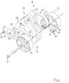
- Reciprocating pistons 4, 4 'and 5, 5' according to FIG. 2 are connected to one another via piston rods 6, 7 connected.
- a jack 8 for the oscillating arrangement of the piston pairs 4, 4 'and 5, 5' by means of the piston rods 6, 7 is a jack 8 with a hypocycloidal straight line 9 provided.
- a line 15 of the crankshaft 10 parallel to the crankshaft axis of rotation 1 symbolizes a crank pin.
- On this crank pin 15 are in the outer End regions that are mounted in the piston rods 6 and 7 parallel to one another Hub eccentric 13, 14 rotatably arranged. Due to the oscillating in the same direction Piston pairs 4, 4 'and 5, 5' are the stroke eccentrics 13, 14 on the common Crank pin 15 arranged in the same direction.
- This leadership eccentric 16 acts with one between the piston rods 6, 7 for reciprocating piston pairs 4, 4 'and 5, 5' of a row of adjacent cylinders 2, 3 arranged guide element 17 of the straight guide 9 together, which is transverse to the directions of movement the piston rods 6 and 7 in the substantially straight guide element 17 principally with guide surfaces arranged on the machine housing cooperates.
- the straight line is hypocycloid 9 of the lifting gear 8 combined with a Watt handlebar 18, the Coupling 19 as a guide element 17 between the piston rods 6 and 7 on the Guide eccentric 16 is arranged mounted.
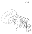
- the coupling 19 is schematic shown swing arms 20 hinged to the machine housing, not shown.
- the swing arms 20 are preferably in their housing-side articulation points 21 each with a rotatable and fixable relative to the machine housing Adjusting eccentric 22 equipped as a means to compensate for dimensional tolerances.
- This setting eccentric 22 are after the assembly of the jack 8 in Machine housing, not shown, one after the other first in one direction rotated to produce a turning resistance, then in the opposite Direction turned until the next resistance and finally about fixed between the two resistance positions.
- the coupling 19 is arranged in its central position, the center of the guide eccentric 16 receiving bore 23 substantially with the crankshaft axis of rotation 1 is aligned or slightly due to dimensional tolerances is parallel spaced.
- the setting eccentrics 22 can in the lifting engine 8 existing bearing games a setting of the paddock 19 can be found, with the coupling 19 over its entire guide stroke between its extreme positions jamming in the lifting engine is safely avoided.
- Arrangement is an automatic setting of the sliding block 26 reached with its hole center relative to the crankshaft axis of rotation 1.
- the backdrop stone 26 can also with the interposition of roller bearing devices, not shown or rolling elements interact with the guide strips 27, 27 'in order to thereby alone or in connection with the displaceable guide strips 27, 27 ' a jamming or self-locking of the straight guide 9 in a TDC area Avoid the pistons 4, 4 ', 5, 5', especially during a cold start.
- a roller bearing arranged on the guide eccentric 16 is provided be that, for example, relocatable with its outer bearing ring arranged guide strips 27, 27 'is slidably connected.
Landscapes
- Engineering & Computer Science (AREA)
- Mechanical Engineering (AREA)
- General Engineering & Computer Science (AREA)
- Chemical & Material Sciences (AREA)
- Combustion & Propulsion (AREA)
- Transmission Devices (AREA)
- Shafts, Cranks, Connecting Bars, And Related Bearings (AREA)
- Reciprocating Pumps (AREA)
Claims (12)
- Moteur à pistons alternatifs comportant des cylindres placés de façon voisine dans la direction du vilebrequin, dans un carter ou bloc moteur, en particulier moteur à combustion interne, comprenant un train moteur (8) destiné à des pistons à mouvements alternatifs (4, 4'; 5, 5'), reliés en entraínement par l'intermédiaire de bielles (6, 7) avec interposition d'un guidage rectiligne (9) de nature hypocycloïdale, avec des excentriques de courses et de guidages (13, 14, 16) mobiles en rotation sur un vilebrequin (10), où un élément de guidage (17) du guidage rectiligne (9) coopère avec des surfaces de guidage disposées sur le carter moteur,
caractérisé en ce qu'
un élément de guidage (17) unique appartenant au guidage rectiligne sert aux deux bielles (6, 7) voisines et est monté à rotation sur un excentrique de guidage (16) disposé entre deux bielles (6, 7) voisines destinées à des pistons (4, 4' ; 5, 5') appartenant à des cylindres (2, 3) voisins dans la rangée. - Moteur à pistons alternatifs selon la revendication 1,
caractérisé en ce que
chaque guidage rectiligne (9) est équipé de moyens destinés à assurer une compensation statique et/ou dynamique des tolérances dimensionnelles entre le carter moteur et le train moteur (8). - Moteur à piston alternatif selon les revendications 1 et 2, caractérisé en ce que,
les pistons alternatifs (4, 4' ; 5, 5') placés à l'opposé dans des paires de cylindres (2, 3) disposées diamétralement sont reliés en entraínement dans le même sens, par l'intermédiaire de bielles (6, 7), où sur un maneton (15) du vilebrequin (10) est disposé, mobile à rotation, centralement, entre deux bielles (6, 7) voisines un excentrique de guidage (16), coopérant avec l'élément de guidage (17) du guidage rectiligne (9) hypocycloïdal qui est relié, de façon assujettie en rotation, à des excentriques de course (13, 14) du guidage rectiligne (9) qui s'engagent, avec une mobilité de rotation, dans les bielles (6, 7) et sont disposés, avec une mobilité de rotation, de part et d'autre de façon voisine sur le maneton (15). - Moteur à pistons alternatifs selon les revendications 1 à 3, caractérisé en ce que
le guidage rectiligne hypocycloïdal (9) est combiné à un bras articulé de Watt (18), dont la bielle (19) est montée à rotation entre les bielles (6, 7) voisines sur l'excentrique de guidage (16), où ses bras oscillants (20), en au moins l'un de leurs points d'articulation (21), sont équipés d'un excentrique de réglage (22), disposé de façon à pouvoir être tourné et être fixé par rapport à la bielle (19) et/ou au carter moteur, pour faire office de moyens de compensation des tolérances dimensionnelles. - Moteur à pistons alternatifs selon les revendications 1 à 4,
caractérisé en ce que,
en chaque point d'articulation (21), situé du coté carter moteur, des bras oscillants (20), est disposé un excentrique de réglage (22) conçu, le cas échéant, pour assurer un réglage automatique. - Moteur à pistons alternatifs selon les revendications 1 à 5
caractérisé en ce que
l'excentrique de guidage (16) est réalisé sous la forme de parties (24,24') susceptibles d'être reliées dans la direction axiale du maneton, où sur chaque partie (24, 24') est disposé, du coté bielle, un excentrique de course (13, 14), ainsi qu'une masse d'équilibrage (25) se référant à l'axe du maneton (15) du vilebrequin. - Moteur à pistons alternatifs selon les revendications 1 à 3,
caractérisé en ce que
l'excentrique de guidage (16) du guidage rectiligne hypocycloïdal (9) est combiné à un élément de guidage (17), guidé avec une mobilité accompagnée de glissement, sur une trajectoire rectiligne, du coté carter moteur, entre les bielles (6, 7) voisines. - Moteur à pistons alternatifs selon les revendications 1 à 3 et 7,
caractérisé en ce que
l'élément de guidage (17) est un patin de coulisse (26) réalisé avec des surfaces de guidage (29, 29') parallèles. - Moteur à pistons alternatifs selon les revendications 1 à 3 et 7,
caractérisé en ce que
l'élément de guidage (17) guidé avec une mobilité accompagnée de glissement est un palier à roulement disposé sur excentrique de guidage (16). - Moteur à pistons alternatifs selon les revendications 1 à 3 et 6 à 9,
caractérisé en ce que,
l'élément de guidage (17) respectif coopère avec des bandes de guidage (27, 27') séparées qui sont disposées de façon à pouvoir se déplacer dans, respectivement sur le carter moteur, transversalement par rapport à la direction du guidage, en vue de compenser les tolérances dimensionnelles et, le cas échéant, coopère avec le patin de coulisse (26) par l'intermédiaire de paliers à roulement. - Moteur à pistons alternatifs selon les revendications 1 à 3 et 6 à 10,
caractérisé en ce que,
les bandes de guidage (27, 27') sont disposées de façon à être déplaçables par l'intermédiaire de pistons (28, 28') sollicités hydrauliquement, disposés dans le carter moteur, où les bandes de guidage (27, 27') sont montés avec une mobilité en basculement par rapport aux pistons (28, 28'). - Moteur à pistons alternatifs selon les revendications 1 à 3 et 6 à 11,
caractérisé en ce quel'excentrique de guidage (16), y compris des masses d'équilibrage (30) disposées dans ses deux zones frontales, est réalisé d'une seule pièce, etle patin de coulisse (26) est subdivisé en moitiés dans la direction de guidage, parallèlement à ses surfaces de guidage (29, 29').
Applications Claiming Priority (3)
| Application Number | Priority Date | Filing Date | Title |
|---|---|---|---|
| DE19504890A DE19504890A1 (de) | 1995-02-14 | 1995-02-14 | Hubkolbenmaschine mit in Kurbelwellenrichtung in einem Maschinengehäuse benachbarten Zylindern |
| DE19504890 | 1995-02-14 | ||
| PCT/EP1996/000631 WO1996025587A1 (fr) | 1995-02-14 | 1996-02-14 | Moteur a pistons alternatifs comportant des cylindres adjacents dans le sens du vilebrequin dans un carter |
Publications (2)
| Publication Number | Publication Date |
|---|---|
| EP0809749A1 EP0809749A1 (fr) | 1997-12-03 |
| EP0809749B1 true EP0809749B1 (fr) | 1999-04-07 |
Family
ID=7753920
Family Applications (1)
| Application Number | Title | Priority Date | Filing Date |
|---|---|---|---|
| EP96904775A Expired - Lifetime EP0809749B1 (fr) | 1995-02-14 | 1996-02-14 | Moteur a pistons alternatifs comportant des cylindres adjacents dans le sens du vilebrequin dans un carter |
Country Status (8)
| Country | Link |
|---|---|
| US (1) | US5943987A (fr) |
| EP (1) | EP0809749B1 (fr) |
| JP (1) | JP3676812B2 (fr) |
| KR (1) | KR100380643B1 (fr) |
| CN (1) | CN1076073C (fr) |
| DE (2) | DE19504890A1 (fr) |
| ES (1) | ES2130801T3 (fr) |
| WO (1) | WO1996025587A1 (fr) |
Cited By (2)
| Publication number | Priority date | Publication date | Assignee | Title |
|---|---|---|---|---|
| DE102005024361A1 (de) * | 2005-05-27 | 2006-12-07 | Bayerische Motoren Werke Ag | Antriebsaggregat für Fahrzeuge |
| DE102014018561B3 (de) * | 2014-12-15 | 2016-01-28 | Gert Fischer | Verbrennungsmotor mit in Linie gegenüberliegenden Zylindern |
Families Citing this family (21)
| Publication number | Priority date | Publication date | Assignee | Title |
|---|---|---|---|---|
| DE19607920A1 (de) | 1996-03-01 | 1997-09-04 | Bayerische Motoren Werke Ag | Hypozykloidisches Kurbelgetriebe für Hubkolbenmaschinen, insbesondere Brennkraftmaschinen |
| DE19623552A1 (de) * | 1996-06-13 | 1997-12-18 | Bayerische Motoren Werke Ag | Hubkolbenmaschine mit einem Hypozykloiden-Kolbenhubgetriebe mit Watt'scher Führung, insbesondere mit Kolben in gegenüberliegenden Zylindern |
| ITTO980080A1 (it) * | 1998-02-02 | 1999-08-02 | Fiat Auto Spa | Manovellismo per una macchina alternativa, particolarmente per un motore a combustione interna |
| UA50790C2 (uk) * | 1999-03-09 | 2002-11-15 | Олексій Феліксович Вуль | Поршнева машина з безшатунним механізмом |
| CN100436779C (zh) * | 2004-08-18 | 2008-11-26 | 何观龙 | 一种内燃机活塞零侧压技术及装置 |
| US7878081B2 (en) * | 2004-12-13 | 2011-02-01 | Gregory S Sundheim | Portable, refrigerant recovery unit |
| US7328682B2 (en) * | 2005-09-14 | 2008-02-12 | Fisher Patrick T | Efficiencies for piston engines or machines |
| US7654802B2 (en) * | 2005-12-22 | 2010-02-02 | Newport Medical Instruments, Inc. | Reciprocating drive apparatus and method |
| WO2008010490A1 (fr) * | 2006-07-18 | 2008-01-24 | Univ Shizuoka Nat Univ Corp | MOTEUR ALTERNATIF cycloïdAL ET POMPE EMPLOYANT CE MÉCANISME DE VILEBREQUIN |
| AU2007312935A1 (en) * | 2006-10-16 | 2008-04-24 | Wintech International Pty Ltd | Hypocycloidal transmission |
| WO2008085920A2 (fr) * | 2007-01-05 | 2008-07-17 | Efficient-V, Inc. | Mécanisme de translation d'un mouvement |
| GB0907496D0 (en) * | 2009-05-01 | 2009-06-10 | Hall Keith G | Engines and drives |
| CN101672264B (zh) * | 2009-09-30 | 2011-10-19 | 浙江鸿友压缩机制造有限公司 | 直线往复活塞式压缩机 |
| CN101886693B (zh) * | 2010-07-02 | 2014-02-12 | 北京中清能发动机技术有限公司 | 一种曲柄圆滑块机构及设备 |
| WO2012075680A1 (fr) * | 2010-12-06 | 2012-06-14 | 北京中清能发动机技术有限公司 | Mécanisme à blocs coulissants circulaires de vilebrequin et élément alternatif, bloc-cylindres, moteur à combustion interne et compresseur |
| US9708976B1 (en) * | 2011-09-30 | 2017-07-18 | Warren Engine Company, Inc. | Opposed piston engine and elements thereof |
| US9119382B2 (en) | 2013-02-26 | 2015-09-01 | Tyson Foods Inc. | Portable basket colony for growing and transport and method of use |
| CN104154195A (zh) * | 2014-07-21 | 2014-11-19 | 苏州市华宁机械制造有限公司 | 一种双偏心轮驱动导杆机构 |
| CN104747674A (zh) * | 2015-01-23 | 2015-07-01 | 陈桢皓 | 动力输出装置、气缸及柴油发动机 |
| AT518769B1 (de) * | 2016-08-18 | 2018-01-15 | Ecool Advanced Urban Eng Gmbh | Brennkraftmaschine |
| JP6734464B1 (ja) * | 2019-12-26 | 2020-08-05 | 竹本 護 | 無振動レシプロエンジン |
Family Cites Families (33)
| Publication number | Priority date | Publication date | Assignee | Title |
|---|---|---|---|---|
| DE271755C (fr) * | ||||
| US848635A (en) * | 1906-04-13 | 1907-04-02 | George S Comstock | Transmission mechanism. |
| US908605A (en) * | 1907-07-05 | 1909-01-05 | Fred C Olin | Crank and yoke connection. |
| US1233621A (en) * | 1914-08-12 | 1917-07-17 | Henry W Jessup | Valve mechanism for internal-combustion engines. |
| US1866702A (en) * | 1930-04-15 | 1932-07-12 | Cooper Bessemer Corp | Driving connection |
| DE725239C (de) * | 1941-03-11 | 1942-09-17 | Ferdinand Meyer | Exzentergetriebe |
| US2302851A (en) * | 1941-11-28 | 1942-11-24 | Joseph F Gelser | Internal combustion engine |
| US2367963A (en) * | 1942-07-22 | 1945-01-23 | Ricardo Harry Ralph | Two-cycle sleeve-valve engine |
| US2513514A (en) * | 1945-10-08 | 1950-07-04 | Robert A Poage | Piston and crankshaft connecting means for internal-combustion engines |
| DE898372C (de) * | 1951-11-30 | 1953-11-30 | Max Ruediger | Mit Ladepumpe arbeitender, schnell laufender Zweitaktmotor mit Verdichtungszuendung, schlitzgesteuert und mit Auslassventil im Zylinderdeckel |
| US3195420A (en) * | 1963-10-17 | 1965-07-20 | Donald J Johannsen | Dual piston unit for internal combustion engine |
| GB1060372A (en) * | 1963-11-13 | 1967-03-01 | Bancroft Charles | Improvements in or relating to reciprocating compressors, pumps, engines and the like |
| DE1301323B (de) * | 1965-06-04 | 1969-08-21 | Elsbett L | Pleuelstange fuer Hochleistungs-Hubkolbenbrennkraftmaschinen |
| US3386429A (en) * | 1966-07-11 | 1968-06-04 | Earl M. Trammell Jr. | Internal combustion engine |
| FR2260199B1 (fr) * | 1974-02-05 | 1977-03-04 | Elhyco Ag | |
| DE2519908A1 (de) * | 1975-05-03 | 1976-11-11 | Juergen Dipl Ing Lambrecht | Hubkolbenmaschine mit exzentrischer nachfuehrung |
| GB2038937A (en) * | 1979-01-04 | 1980-07-30 | Suzuku K | Reciprocating Piston Engine |
| FR2482190A1 (fr) * | 1980-05-08 | 1981-11-13 | Abeillon Jackie | Amplificateur de puissance pour moteurs thermiques ou autres |
| US4559686A (en) * | 1980-06-11 | 1985-12-24 | Tecumseh Products Company | Method of assembling a hermetic compressor |
| US4450754A (en) * | 1980-08-18 | 1984-05-29 | Liljequist Jon L | Mechanical arrangements for piston-crankshaft devices |
| GB8608237D0 (en) * | 1986-04-04 | 1986-05-08 | Collins Motor Corp Ltd | Reciprocatory positive displacement machines |
| DE3636873A1 (de) * | 1986-10-30 | 1988-05-11 | Forsch Kraftfahrwesen Und Fahr | Synchronisiergetriebe an einem hypozykloidengetriebe fuer eine hubkolbenmaschine |
| GB8712645D0 (en) * | 1987-05-29 | 1987-07-01 | Collins Motor Corp Ltd | Interconnecting rotary & reciprocatory motion |
| DE3824521A1 (de) * | 1988-07-20 | 1990-01-25 | Heinrich Rode | Hypozykloiden-motor (verbrennungs-kraftmaschine) |
| GB2229248A (en) * | 1989-03-15 | 1990-09-19 | Ford Motor Co | Phase change mechanism |
| DE3927593A1 (de) * | 1989-08-22 | 1991-02-28 | Bayerische Motoren Werke Ag | Hubgetriebe, insbesondere fuer hubkolbenmaschinen |
| AU642718B2 (en) * | 1990-02-21 | 1993-10-28 | Collins Motor Corporation Limited | Interconnecting rotary and reciprocating motion |
| DE4108311C2 (de) * | 1991-03-14 | 2000-09-21 | Bayerische Motoren Werke Ag | Hypozykloiden-Hubgetriebe für Hubkolbenmaschinen in Boxerbauart |
| DE4142385A1 (de) * | 1991-12-20 | 1993-06-24 | Bayerische Motoren Werke Ag | Mehrzylindrige hubkolbenmaschine mit einem hypozykloid-hubgetriebe, insbesondere brennkraftmaschine |
| DE4204319A1 (de) * | 1992-02-13 | 1993-08-19 | Norbert Kraemer | Brennkraftmaschine |
| US5331926A (en) * | 1993-07-23 | 1994-07-26 | Denner, Inc. | Dwelling scotch yoke engine |
| DE4412165A1 (de) * | 1994-04-08 | 1994-09-01 | Viktor Hammermeister | Kurbelgetriebe zur Umwandlung von geradelinigen Hin- und Herbewegungen in Drehbewegungen und umgekehrt |
| DE19607920A1 (de) * | 1996-03-01 | 1997-09-04 | Bayerische Motoren Werke Ag | Hypozykloidisches Kurbelgetriebe für Hubkolbenmaschinen, insbesondere Brennkraftmaschinen |
-
1995
- 1995-02-14 DE DE19504890A patent/DE19504890A1/de not_active Withdrawn
-
1996
- 1996-02-14 US US08/894,178 patent/US5943987A/en not_active Expired - Lifetime
- 1996-02-14 JP JP52466296A patent/JP3676812B2/ja not_active Expired - Fee Related
- 1996-02-14 ES ES96904775T patent/ES2130801T3/es not_active Expired - Lifetime
- 1996-02-14 EP EP96904775A patent/EP0809749B1/fr not_active Expired - Lifetime
- 1996-02-14 CN CN96191881A patent/CN1076073C/zh not_active Expired - Fee Related
- 1996-02-14 KR KR1019970704503A patent/KR100380643B1/ko not_active Expired - Fee Related
- 1996-02-14 WO PCT/EP1996/000631 patent/WO1996025587A1/fr not_active Ceased
- 1996-02-14 DE DE59601612T patent/DE59601612D1/de not_active Expired - Lifetime
Cited By (2)
| Publication number | Priority date | Publication date | Assignee | Title |
|---|---|---|---|---|
| DE102005024361A1 (de) * | 2005-05-27 | 2006-12-07 | Bayerische Motoren Werke Ag | Antriebsaggregat für Fahrzeuge |
| DE102014018561B3 (de) * | 2014-12-15 | 2016-01-28 | Gert Fischer | Verbrennungsmotor mit in Linie gegenüberliegenden Zylindern |
Also Published As
| Publication number | Publication date |
|---|---|
| CN1173907A (zh) | 1998-02-18 |
| JP3676812B2 (ja) | 2005-07-27 |
| ES2130801T3 (es) | 1999-07-01 |
| EP0809749A1 (fr) | 1997-12-03 |
| JPH11500200A (ja) | 1999-01-06 |
| DE19504890A1 (de) | 1996-08-22 |
| CN1076073C (zh) | 2001-12-12 |
| KR100380643B1 (ko) | 2003-07-18 |
| US5943987A (en) | 1999-08-31 |
| WO1996025587A1 (fr) | 1996-08-22 |
| DE59601612D1 (de) | 1999-05-12 |
Similar Documents
| Publication | Publication Date | Title |
|---|---|---|
| EP0809749B1 (fr) | Moteur a pistons alternatifs comportant des cylindres adjacents dans le sens du vilebrequin dans un carter | |
| EP2524127B1 (fr) | Moteur en ligne avec commande à manivelle à articulation multiple avec un seul arbre d'équilibrage | |
| DD256894A5 (de) | Kolben-verbrennungsmotoren | |
| DE2639260C3 (de) | Mehrzylindrige Hubkolben-Brennkraftmaschine | |
| DE19607920A1 (de) | Hypozykloidisches Kurbelgetriebe für Hubkolbenmaschinen, insbesondere Brennkraftmaschinen | |
| EP0815370B1 (fr) | Transmission a manivelle hypocycloidale pour machines a pistons a mouvement alternatif, en particulier les moteurs a combustion interne ayant des rangees de cylindres opposees | |
| DE102010004588B4 (de) | Brennkraftmaschine mit verlängertem Expansionshub und Ausgleichsgewichten auf der Exzenterwelle | |
| DE10348345B4 (de) | Hubkolben-Brennkraftmaschine | |
| DE102012008244B4 (de) | Mehrgelenkskurbeltrieb einer Brennkraftmaschine | |
| DE2816429C2 (de) | Mechanischer Pressenantrieb | |
| DE69936522T3 (de) | Steifer kurbelwellenhalter und betätigungsvorrichtung | |
| WO2013110470A1 (fr) | Mécanisme à bielle et manivelle à articulations multiples d'un moteur à combustion interne et procédé de montage d'un mécanisme à bielle et manivelle à articulations multiples | |
| DE3927593A1 (de) | Hubgetriebe, insbesondere fuer hubkolbenmaschinen | |
| DE3642681A1 (de) | Kurbelwelle, insbesondere fuer hubkolben-verbrennungsmaschinen | |
| DE102013019214B3 (de) | Mehrgelenkskurbeltrieb einer Brennkraftmaschine sowie Verfahren zum Betreiben eines Mehrgelenkskurbeltriebs | |
| DE3420956A1 (de) | Synchronisiergetriebe fuer ein zentrisches, gleichschenkliges geradschubkurbelgetriebe einer hubkolbenmaschine | |
| DE19500854C2 (de) | Hubkolbenmaschine | |
| WO1988004356A1 (fr) | Embiellage, notamment pour moteurs a piston alternatif | |
| WO2015090605A1 (fr) | Organe d'accouplement pour embiellage à plusieurs articulations et embiellage à plusieurs articulations | |
| DE866115C (de) | Kolbenmaschine mit Taumelscheibe, insbesondere Brennkraftkolbenmaschine | |
| DE4237463C2 (de) | Ausgleichsgetriebe | |
| DE2723269C2 (de) | Mehrzylindrige Hubkolbenmaschine | |
| DE102009038850B4 (de) | Boxermotor mit Kulissenpleuel | |
| DE2602436A1 (de) | Kolben-kraft- und arbeitsmaschine | |
| DE514780C (de) | Axial-Kolbenmaschine, insbesondere Brennkraftmaschine, bei welcher die Kolben mit einer Taumelscheibe verbunden sind |
Legal Events
| Date | Code | Title | Description |
|---|---|---|---|
| PUAI | Public reference made under article 153(3) epc to a published international application that has entered the european phase |
Free format text: ORIGINAL CODE: 0009012 |
|
| 17P | Request for examination filed |
Effective date: 19970528 |
|
| AK | Designated contracting states |
Kind code of ref document: A1 Designated state(s): DE ES FR GB IT |
|
| GRAG | Despatch of communication of intention to grant |
Free format text: ORIGINAL CODE: EPIDOS AGRA |
|
| 17Q | First examination report despatched |
Effective date: 19980623 |
|
| GRAG | Despatch of communication of intention to grant |
Free format text: ORIGINAL CODE: EPIDOS AGRA |
|
| GRAH | Despatch of communication of intention to grant a patent |
Free format text: ORIGINAL CODE: EPIDOS IGRA |
|
| GRAH | Despatch of communication of intention to grant a patent |
Free format text: ORIGINAL CODE: EPIDOS IGRA |
|
| GRAA | (expected) grant |
Free format text: ORIGINAL CODE: 0009210 |
|
| AK | Designated contracting states |
Kind code of ref document: B1 Designated state(s): DE ES FR GB IT |
|
| GBT | Gb: translation of ep patent filed (gb section 77(6)(a)/1977) |
Effective date: 19990408 |
|
| REF | Corresponds to: |
Ref document number: 59601612 Country of ref document: DE Date of ref document: 19990512 |
|
| ET | Fr: translation filed | ||
| REG | Reference to a national code |
Ref country code: ES Ref legal event code: FG2A Ref document number: 2130801 Country of ref document: ES Kind code of ref document: T3 |
|
| PLBE | No opposition filed within time limit |
Free format text: ORIGINAL CODE: 0009261 |
|
| STAA | Information on the status of an ep patent application or granted ep patent |
Free format text: STATUS: NO OPPOSITION FILED WITHIN TIME LIMIT |
|
| 26N | No opposition filed | ||
| REG | Reference to a national code |
Ref country code: GB Ref legal event code: IF02 |
|
| PGFP | Annual fee paid to national office [announced via postgrant information from national office to epo] |
Ref country code: IT Payment date: 20110224 Year of fee payment: 16 Ref country code: FR Payment date: 20110315 Year of fee payment: 16 |
|
| PGFP | Annual fee paid to national office [announced via postgrant information from national office to epo] |
Ref country code: ES Payment date: 20110131 Year of fee payment: 16 Ref country code: DE Payment date: 20110402 Year of fee payment: 16 |
|
| PGFP | Annual fee paid to national office [announced via postgrant information from national office to epo] |
Ref country code: GB Payment date: 20120223 Year of fee payment: 17 |
|
| REG | Reference to a national code |
Ref country code: FR Ref legal event code: ST Effective date: 20121031 |
|
| PG25 | Lapsed in a contracting state [announced via postgrant information from national office to epo] |
Ref country code: IT Free format text: LAPSE BECAUSE OF NON-PAYMENT OF DUE FEES Effective date: 20120214 |
|
| REG | Reference to a national code |
Ref country code: DE Ref legal event code: R119 Ref document number: 59601612 Country of ref document: DE Effective date: 20120901 |
|
| PG25 | Lapsed in a contracting state [announced via postgrant information from national office to epo] |
Ref country code: FR Free format text: LAPSE BECAUSE OF NON-PAYMENT OF DUE FEES Effective date: 20120229 |
|
| PG25 | Lapsed in a contracting state [announced via postgrant information from national office to epo] |
Ref country code: DE Free format text: LAPSE BECAUSE OF NON-PAYMENT OF DUE FEES Effective date: 20120901 |
|
| REG | Reference to a national code |
Ref country code: ES Ref legal event code: FD2A Effective date: 20130708 |
|
| PG25 | Lapsed in a contracting state [announced via postgrant information from national office to epo] |
Ref country code: ES Free format text: LAPSE BECAUSE OF NON-PAYMENT OF DUE FEES Effective date: 20120215 |
|
| GBPC | Gb: european patent ceased through non-payment of renewal fee |
Effective date: 20130214 |
|
| PG25 | Lapsed in a contracting state [announced via postgrant information from national office to epo] |
Ref country code: GB Free format text: LAPSE BECAUSE OF NON-PAYMENT OF DUE FEES Effective date: 20130214 |