EP0809751B1 - Temperaturregelung für eine flüssigkeitskonditionierungsanordnung - Google Patents
Temperaturregelung für eine flüssigkeitskonditionierungsanordnung Download PDFInfo
- Publication number
- EP0809751B1 EP0809751B1 EP96901055A EP96901055A EP0809751B1 EP 0809751 B1 EP0809751 B1 EP 0809751B1 EP 96901055 A EP96901055 A EP 96901055A EP 96901055 A EP96901055 A EP 96901055A EP 0809751 B1 EP0809751 B1 EP 0809751B1
- Authority
- EP
- European Patent Office
- Prior art keywords
- liquid
- housing
- heat exchange
- bulkhead
- chamber
- Prior art date
- Legal status (The legal status is an assumption and is not a legal conclusion. Google has not performed a legal analysis and makes no representation as to the accuracy of the status listed.)
- Expired - Lifetime
Links
- 239000007788 liquid Substances 0.000 title claims abstract description 96
- 230000003750 conditioning effect Effects 0.000 title claims abstract description 21
- 230000001105 regulatory effect Effects 0.000 title claims abstract description 9
- 238000004140 cleaning Methods 0.000 claims abstract description 71
- 238000012546 transfer Methods 0.000 claims description 13
- 239000012530 fluid Substances 0.000 claims description 10
- 230000001143 conditioned effect Effects 0.000 claims description 3
- 238000004891 communication Methods 0.000 claims description 2
- 239000010687 lubricating oil Substances 0.000 abstract description 10
- 238000001816 cooling Methods 0.000 abstract description 7
- 238000010438 heat treatment Methods 0.000 abstract description 7
- 230000000694 effects Effects 0.000 abstract description 3
- 239000000314 lubricant Substances 0.000 description 6
- 238000002485 combustion reaction Methods 0.000 description 3
- 239000000356 contaminant Substances 0.000 description 3
- 230000005484 gravity Effects 0.000 description 3
- 239000011159 matrix material Substances 0.000 description 3
- 239000007787 solid Substances 0.000 description 3
- 238000006243 chemical reaction Methods 0.000 description 2
- 239000004020 conductor Substances 0.000 description 2
- 210000004907 gland Anatomy 0.000 description 2
- 230000001050 lubricating effect Effects 0.000 description 2
- 238000005461 lubrication Methods 0.000 description 2
- NJPPVKZQTLUDBO-UHFFFAOYSA-N novaluron Chemical compound C1=C(Cl)C(OC(F)(F)C(OC(F)(F)F)F)=CC=C1NC(=O)NC(=O)C1=C(F)C=CC=C1F NJPPVKZQTLUDBO-UHFFFAOYSA-N 0.000 description 2
- XLYOFNOQVPJJNP-UHFFFAOYSA-N water Substances O XLYOFNOQVPJJNP-UHFFFAOYSA-N 0.000 description 2
- 238000013459 approach Methods 0.000 description 1
- 230000004323 axial length Effects 0.000 description 1
- 230000009286 beneficial effect Effects 0.000 description 1
- 238000005266 casting Methods 0.000 description 1
- 238000009833 condensation Methods 0.000 description 1
- 230000005494 condensation Effects 0.000 description 1
- 238000010276 construction Methods 0.000 description 1
- 238000006073 displacement reaction Methods 0.000 description 1
- 238000001704 evaporation Methods 0.000 description 1
- 230000008020 evaporation Effects 0.000 description 1
- 230000001747 exhibiting effect Effects 0.000 description 1
- 238000001914 filtration Methods 0.000 description 1
- CNQCVBJFEGMYDW-UHFFFAOYSA-N lawrencium atom Chemical compound [Lr] CNQCVBJFEGMYDW-UHFFFAOYSA-N 0.000 description 1
- 238000012423 maintenance Methods 0.000 description 1
- 238000000034 method Methods 0.000 description 1
- 239000003921 oil Substances 0.000 description 1
- 239000002245 particle Substances 0.000 description 1
Images




Classifications
-
- B—PERFORMING OPERATIONS; TRANSPORTING
- B01—PHYSICAL OR CHEMICAL PROCESSES OR APPARATUS IN GENERAL
- B01D—SEPARATION
- B01D36/00—Filter circuits or combinations of filters with other separating devices
- B01D36/04—Combinations of filters with settling tanks
- B01D36/045—Combination of filters with centrifugal separation devices
-
- F—MECHANICAL ENGINEERING; LIGHTING; HEATING; WEAPONS; BLASTING
- F01—MACHINES OR ENGINES IN GENERAL; ENGINE PLANTS IN GENERAL; STEAM ENGINES
- F01M—LUBRICATING OF MACHINES OR ENGINES IN GENERAL; LUBRICATING INTERNAL COMBUSTION ENGINES; CRANKCASE VENTILATING
- F01M1/00—Pressure lubrication
- F01M1/10—Lubricating systems characterised by the provision therein of lubricant venting or purifying means, e.g. of filters
-
- F—MECHANICAL ENGINEERING; LIGHTING; HEATING; WEAPONS; BLASTING
- F01—MACHINES OR ENGINES IN GENERAL; ENGINE PLANTS IN GENERAL; STEAM ENGINES
- F01M—LUBRICATING OF MACHINES OR ENGINES IN GENERAL; LUBRICATING INTERNAL COMBUSTION ENGINES; CRANKCASE VENTILATING
- F01M11/00—Component parts, details or accessories, not provided for in, or of interest apart from, groups F01M1/00 - F01M9/00
- F01M11/03—Mounting or connecting of lubricant purifying means relative to the machine or engine; Details of lubricant purifying means
-
- F—MECHANICAL ENGINEERING; LIGHTING; HEATING; WEAPONS; BLASTING
- F01—MACHINES OR ENGINES IN GENERAL; ENGINE PLANTS IN GENERAL; STEAM ENGINES
- F01M—LUBRICATING OF MACHINES OR ENGINES IN GENERAL; LUBRICATING INTERNAL COMBUSTION ENGINES; CRANKCASE VENTILATING
- F01M5/00—Heating, cooling, or controlling temperature of lubricant; Lubrication means facilitating engine starting
- F01M5/002—Cooling
-
- B—PERFORMING OPERATIONS; TRANSPORTING
- B01—PHYSICAL OR CHEMICAL PROCESSES OR APPARATUS IN GENERAL
- B01D—SEPARATION
- B01D35/00—Filtering devices having features not specifically covered by groups B01D24/00 - B01D33/00, or for applications not specifically covered by groups B01D24/00 - B01D33/00; Auxiliary devices for filtration; Filter housing constructions
- B01D35/18—Heating or cooling the filters
-
- F—MECHANICAL ENGINEERING; LIGHTING; HEATING; WEAPONS; BLASTING
- F01—MACHINES OR ENGINES IN GENERAL; ENGINE PLANTS IN GENERAL; STEAM ENGINES
- F01M—LUBRICATING OF MACHINES OR ENGINES IN GENERAL; LUBRICATING INTERNAL COMBUSTION ENGINES; CRANKCASE VENTILATING
- F01M1/00—Pressure lubrication
- F01M1/10—Lubricating systems characterised by the provision therein of lubricant venting or purifying means, e.g. of filters
- F01M2001/1007—Lubricating systems characterised by the provision therein of lubricant venting or purifying means, e.g. of filters characterised by the purification means combined with other functions
- F01M2001/1014—Lubricating systems characterised by the provision therein of lubricant venting or purifying means, e.g. of filters characterised by the purification means combined with other functions comprising supply of additives
-
- F—MECHANICAL ENGINEERING; LIGHTING; HEATING; WEAPONS; BLASTING
- F01—MACHINES OR ENGINES IN GENERAL; ENGINE PLANTS IN GENERAL; STEAM ENGINES
- F01M—LUBRICATING OF MACHINES OR ENGINES IN GENERAL; LUBRICATING INTERNAL COMBUSTION ENGINES; CRANKCASE VENTILATING
- F01M1/00—Pressure lubrication
- F01M1/10—Lubricating systems characterised by the provision therein of lubricant venting or purifying means, e.g. of filters
- F01M2001/1028—Lubricating systems characterised by the provision therein of lubricant venting or purifying means, e.g. of filters characterised by the type of purification
- F01M2001/1035—Lubricating systems characterised by the provision therein of lubricant venting or purifying means, e.g. of filters characterised by the type of purification comprising centrifugal filters
-
- F—MECHANICAL ENGINEERING; LIGHTING; HEATING; WEAPONS; BLASTING
- F01—MACHINES OR ENGINES IN GENERAL; ENGINE PLANTS IN GENERAL; STEAM ENGINES
- F01M—LUBRICATING OF MACHINES OR ENGINES IN GENERAL; LUBRICATING INTERNAL COMBUSTION ENGINES; CRANKCASE VENTILATING
- F01M11/00—Component parts, details or accessories, not provided for in, or of interest apart from, groups F01M1/00 - F01M9/00
- F01M11/03—Mounting or connecting of lubricant purifying means relative to the machine or engine; Details of lubricant purifying means
- F01M2011/031—Mounting or connecting of lubricant purifying means relative to the machine or engine; Details of lubricant purifying means characterised by mounting means
- F01M2011/033—Mounting or connecting of lubricant purifying means relative to the machine or engine; Details of lubricant purifying means characterised by mounting means comprising coolers or heat exchangers
-
- F—MECHANICAL ENGINEERING; LIGHTING; HEATING; WEAPONS; BLASTING
- F28—HEAT EXCHANGE IN GENERAL
- F28F—DETAILS OF HEAT-EXCHANGE AND HEAT-TRANSFER APPARATUS, OF GENERAL APPLICATION
- F28F2280/00—Mounting arrangements; Arrangements for facilitating assembling or disassembling of heat exchanger parts
- F28F2280/02—Removable elements
Definitions
- This invention relates to conditioning arrangements for conditioning a liquid circulated through a system, and in particular to regulating the temperature of the liquid.
- Liquid may typically be circulated through a system to provide motive power to one or more elements of the system or to provide lubrication to bearings of an engine or the like.
- a lubricating liquid oil
- a conditioning arrangement which conditions the liquid by cleaning the liquid of solid contaminants.
- GB-A-2160796, GB-A-2160449 and DE-C1-4306431 examples of such arrangements containing both cleaning element types are disclosed in GB-A-2160796, GB-A-2160449 and DE-C1-4306431, all of which disclose coaxially arranged full flow and centrifugal cleaning elements within housing means that is arranged to be coupled to an engine block.
- the housing means forms part of a liquid lubricant circulation system of the engine, receiving a liquid lubricant therefrom and returning it thereto by way of aligned passages or ducts. Most of the liquid, after passage through the full flow element is returned to the engine under pressure in order to lubricate bearings etc. whereas a proportion of the lubricant by-passes that element to the centrifugal cleaning element from which it is returned directly to a reservoir or sump.
- GB-A-2160449 discloses the coaxially disposed cleaning elements, one surrounding the other, and capable of separate removal in an axial direction
- GB-A-2160796 discloses the cleaning elements axially displaced and accessible from different axial directions by way of separately removable parts of the housing means.
- DE-C1-4306431 discloses both cleaning elements axially displaced within a single housing and removable in the same axial direction.
- heating and/or cooling means associated with lubricating liquid for use by an engine as it is circulated and cleaned by a typical full flow cleaning element.
- Such means may take the form of a heat exchanger matrix disposed separately of the engine block, usually where it is in a stream of cooler air caused to pass across it, and liquid is piped from the engine thereto and back again.
- a matrix may have a full flow filter in line with the liquid flow, but the use of a discrete matrix and external pipework increase capital and maintenance costs, assuming space is available, whilst also being potentially vulnerable to damage.
- the damage that can be caused by loss of liquid lubricant, each at a small rate in a relatively short interval, compared with the wide tolerance of viscosity changes acceptable to most engines, means that temperature regulation of the liquid by such externally effected lubricant cooling is employed only where it is considered essential, not merely beneficial to engine efficiency.
- engines which have the liquid cleaned by a full flow cleaning element of the self-contained kind, that is, as a sealed canister containing a paper, or like, filter element and adapted to be screwed onto a mounting block which also transfers liquid to and from the engine may have the mounting block adapted to include or support a simple heat exchanger element in the form of a water jacket to which the canister is actually screwed and through which the liquid is directed by additional pipework or ducting.
- liquid lubricant cleaning arrangements which have such associated heat exchanger element are disclosed in GB-A-2163967, EP-A-0200809, DE-C-3444267 and DE-A-1934193.
- the mounting is adapted such that the heat exchanger is formed integrally within it, it becomes a complex casting, whereas if it is a separate element interposed between conventional mounting block and the cleaning element canister, there are two interfaces for liquid transfer that have potential for leakage.
- Such arrangements as described also introduce resistance into the liquid flow by forcing it through confined passage of the heat exchanger and do not offer a cost effective approach to effecting such cooling, or possibly heating, of liquid when the cleaning includes not only a full flow cleaning element but also a self-powered centrifugal cleaner to operate on a proportion of the liquid by-passing the full flow cleaning element.
- liquid cleaning and conditioning systems are not restricted only to lubricating oil systems of internal combustion engines, and preserving the generality of the foregoing it is an object of the present invention to provide a liquid temperature regulating liquid conditioning arrangement which includes liquid filtering by both full flow and centrifugal cleaning elements that is of simple, compact and practicable construction and which mitigates actual or potential disadvantages of techniques hitherto adapted to perform a similar function.
- a temperature regulating liquid conditioning arrangement comprises housing means, adapted for attachment to apparatus for supplying liquid under pressure and utilising conditioned liquid returned thereto, having defined therein a plurality of chambers arranged individually to contain centrifugal and full flow cleaning elements disposed coaxially with respect to each other and with respect to a single housing closure means providing access to the housing chambers, and heat exchange means comprising a heat exchange element operably disposed within a chamber of the housing filled with the liquid and in the liquid flow path of the full flow cleaning element such that the liquid is exposed to the heat exchange element.
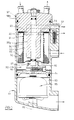
- a temperature regulating liquid conditioning arrangement 10 comprises a housing 11 that is a generally tubular body surrounding a longitudinal axis 12 thereof having laterally extending passages 13 1 ... 13 4 adapted to line up with corresponding lubricant 14 1 ... 14 4 in an engine block 15 to which the housing is operably secured with the axis 12 substantially vertical.
- the housing is closed at one axial end 11 1 which forms a floor or base but open at the other end 11 2 .
- the housing is divided into three discrete chambers 16, 17 and 18 by bulkhead means comprising removable bulkheads 19 and 20.
- the bulkhead 19 is arranged to locate against shoulder 19 1 in the housing wall to limit its proximity to the end wall 11 1 and a radially contractible snap ring 19 2 is arranged to locate in a groove in the housing wall above the bulkhead to act as a retainer therefor should the housing become inverted.
- the lower chamber 16 contains lateral passage 13 1 which couples by way of engine block duct 14 1 to an engine sump (not shown) containing a reservoir of liquid lubricant and the end wall 11, of the housing defines a sloping floor to the chamber permitting liquid to empty therefrom by gravity.
- the end wall 11 1 of the housing also has a pedestal 22 extending axially into the chamber 16 on which is mounted for rotation about the axis a centrifugal cleaner element 23, the element being supported at its upper end by a tubular spindle 24 which extends down through the bulkhead 19 and supplies liquid to the inside of the element.
- the bulkhead 19 also contains a valve 25 which controls the passage of liquid through the bulkhead and into the spindle 24 from middle chamber 17, the valve being closed by a bias spring 26 such that it is only opened when the pressure of liquid in the chamber 17 exceeds a predetermined minimum at which it is appropriate to direct some of it through the centrifugal cleaner.
- the middle chamber 17 connects with liquid inlet passage 13 2 , which couples by way of engine block duct 14 2 to receive pressurised liquid from a pump (not shown) driven by the engine and contains a full flow cleaning element 27, comprising a tubular body of pleated mesh contained between end caps 27 1 and 27 2 .
- the lower end cap 27 1 is supported on the bulkhead 19 and by way of a spring 28 therebetween the upper end cap 27 2 , which is centrally opened, is biased against bulkhead 20 such that the central aperture 29 is aligned with an axial passage 30 in the bulkhead.
- the bulkhead 20 is secured with respect to the housing, being prevented from displacement towards the open end of the housing, by a radially contractible snap ring 31 locatable in a recess in the housing wall and supports at its centre, surrounding passage 30, a stand tube 32 which extends through the upper chamber 18 along the axis.
- the stand tube has lateral apertures 33 connecting with the chamber and is threaded at its upper end 34 to receive removable closure means indicated generally at 35, for both the stand tube and the surrounding chamber, and being therefore closure means for the housing.
- the upper chamber 18 connects with liquid outlet passages 13 3 and 13 4 , the former being connected to engine block duct 14 3 to supply liquid to bearings and like parts of the engine requiring a constant supply of cleaned lubricant delivered at an optimum pressure and the latter being connected by way of engine block duct 14 4 to the sump when a pressure relief valve 21 opens to return pumped liquid to the sump if the pressure in passage 13, exceeds the optimum pressure.
- liquid is supplied by way of duct 13 2 to chamber 17; the liquid passes in a generally radial direction through the apertured screen mesh of full flow cleaning element 27 and then to the centre region thereof from which it passes through the end cap aperture 29 and bulkhead passage 30 (and by way of stand tube 32 and upper chamber 18) to exit along passage 13 3 .
- bias of valve 25 in the bulkhead 19 is overcome and liquid therefrom is permitted to enter the axial passage 24 and thus centrifugal cleaning element 23, exiting from the element by way of reaction nozzles 23' before returning to the sump by way of passage 13 1 .
- the heat exchange means comprises a source 41 of a heat transfer medium, conveniently a liquid such as water having good thermal conductivity, although to avoid confusion with the liquid to be conditioned, it is convenient to refer to it throughout this specification as the "medium".
- the source 41 may also be a conventional radiator exposed to a flow of cool air.
- the heat exchange means also comprises a heat exchange element 42 having conduction means for the medium, namely inlet and outlet pipes 43, 44 respectively, joined by one or more heat exchanging pipes 45, possibly with heat conducting fins 46, which extends axially into the chamber 18 and around central stand tube 32.
- the heat exchange element is operably immersed in the liquid that fills the chamber such that the liquid flowing through the chamber between the stand tube apertures 33 and the outlet passage 13, flows across the surface of the heat exchange element which can conduct heat to the medium and vice versa.
- the heat exchange element is mechanically connected to a central nut member 47 and comprises therewith the removable closure means 35 for the housing.
- the heat exchange means further comprises means 49, such as a circulating pump, to cause the medium to pass from inlet to outlet pipe by way of the heat exchanging pipe(s) 45 to effect a transfer of heat by way of each heat exchanging pipe in response to a temperature difference between the medium and the liquid.
- means 49 such as a circulating pump
- the heat exchange means 40 may include sensing means, such as indicated at 51 disposed in the outlet passage 13 3 or at some other point in the housing or engine to sense a parameter at least related to the temperature of the liquid, that is, the temperature itself or the related parameter such as viscosity, means to vary the effective thermal capacity of the fluid medium, such as the circulating pump 49 and heat exchanger 41, and control means 52, operable in response to signals from the sensing means and a demand or datum source 53 which represents a demanded temperature for the liquid, to vary the effective thermal capacity of the medium by way of the circulating rate of pump 49 and/or radiating efficiency of heat exchanger 41 to maintain the temperature of the liquid substantially at the demanded value.
- sensing means such as indicated at 51 disposed in the outlet passage 13 3 or at some other point in the housing or engine to sense a parameter at least related to the temperature of the liquid, that is, the temperature itself or the related parameter such as viscosity
- control means 52 operable in response to signals from the sensing means and a demand or datum source
- heat exchange means may take a variety of different forms which will be recognised by those skilled in the art of temperature regulation and implemented without the need for detailed descriptions.
- the heat exchange means may operate with a medium comprising a volatile liquid that is both circulated and compressed by the circulating pump 49, that is, as a refrigerator, or may operate other than with a forced circulating pump 49, the liquid being caused to circulate by way of 'gravity' convection currents or by some other mechanism, such as a heat pipe, that operates by a combination of evaporation and condensation of a volatile liquid.
- the fluid medium may alternatively be of a purely gaseous nature rather than a liquid.
- the heat exchange means may be other than a closed system that restores fluid temperature and recycles it, discarding the fluid medium after passage through the heat exchange element and replenishing it with fresh fluid.
- the heat exchange means may provide heating as well as, or instead of, cooling of the liquid by use of a heat exchanger 41 which includes a source of heat.
- a heat exchanger 41 which includes a source of heat.
- Such heat particularly when required prior to starting the engine and/or to rapidly modify a normally cooling effect a fluid medium, may be provided by using an electric current as the heat transfer medium and one or more electrical conductors (being heating elements) disposed in the chamber 18.
- the precise structure of the heat exchange element is open to variation, but preferably, when it occupies its own discrete chamber, it has a structure which serves to act to maximise the path between the chamber inlet apertures 33 and outlet passage 13 3 and thus the dwell time of the liquid in the chamber.
- the closure means 35 in carrying the heat exchange element therewith, when removed from the housing by removal of nut 47 also removes the heat exchange element and provide ready access to the full flow cleaning element 27 (after removal of snap ring 31 and bulkhead 20) and centrifugal cleaning element 23 (after removal of the element 27, snap ring 19 2 and bulkhead 19).
- heat exchange element may be disposed differently with respect to the housing and the cleaning elements, particularly the full flow element, therein.
- a second form of temperature regulating liquid conditioning arrangement 60 comprises a generally tubular housing 61 having an operably vertically disposed longitudinal axis 62 and is divided lengthwise into three chambers 63, 64 and 65 by removable bulkheads 66 and 67.
- a cover 68 of chamber 65 supports a centrifugal cleaner element 69 mounted on bulkhead 67 and the middle chamber 64 contains a full flow cleaner element 70 mounted between the bulkheads.
- the lower chamber 63 which receives liquid from the full flow element by way of axial passage 72, contains a heat exchange element 73 which rests against the end of the housing and is secured by way of gland seals 74 secured to the inlet and outlet pipes 75, 76 respectively. Operation is essentially as described above for the arrangement 10, except that the heat exchange element does not require to be removed to access the cleaning elements.
- a third form of liquid conditioning arrangement 80 comprises a generally tubular housing 81 similar to the housing 11 described above and having an operably vertically disposed longitudinal axis 82.
- the housing has a lower chamber 83 defined by bulkhead 84 and containing a centrifugal cleaning element 85 that is mounted between the bulkhead and floor of the housing.
- the bulkhead 84 defines above it a chamber 86 and has an upwardly extending pedestal 87 upon which is supported a full flow cleaning element 88.
- the cleaning element 88 comprises a closed lower end piece 89 upon which is supported an annular pleated mesh screen 90 through which liquid in the chamber flows in a radially inward direction.
- the mesh screen is supported for strength by a perforated tube 91 which extends between the lower end piece 89 and an upper end piece 92 having central aperture 93.
- the mesh screen is surrounded for part of its length by an unperforated baffle 94 which constrains the liquid that flows radially through the mesh to flow also lengthwise before it is permitted to pass through the perforated tube 91 and into a central region 95, which region is in communication with outlet passage 96.
- Removable closure means for the housing also comprises a heat exchange element 98 which shares the chamber 86 with the full flow cleaning element.
- An upper part 98 1 is solid and forms a removable sealable closure for the housing, whilst the lower part 98 2 comprises heat transfer medium conductors, such as the fluid carrying pipes or the like described above.
- the heat exchange element extends axially parallel to the full flow element and is surrounded thereby.
- the arrangement 80 is functionally similar to the arrangement 10, there is one less bulkhead within the housing and the full flow cleaning element and heat exchange element has greater axial length without extending the housing.
- housing 101 having operably vertical axis 102 contains a centrifugal cleaning element 103 in a lower chamber 104 defined by a modified form of bulkhead 105 which supports, and supplies liquid to, the centre part 106 of a full flow cleaning element 107.
- the cleaning element is surrounded by a lower part 109 2 of heat exchange element 109 whose upper part 109 1 forms a removable closure for the housing indicated by 110.
- the arrangements 80 and 100 have been shown with the heat exchange element in the upper part of the housing and carried by, and removable with housing closure means, it may also be disposed similarly with respect to the full flow cleaning element, that is, ... element surrounding the other, in the lower part of the housing in the manner of Figure 2.
- housing 121 comprises a base portion 122 and a closure 125 which defines, by way of axially extending inner and out walls 126 and 127, a central chamber 128 and a surrounding chamber 129.
- the base portion 122 supports a centrifugal cleaning element 130 for rotation about an operably vertical axis 131 within the central chamber 128 whereas the surrounding chamber 129 contains an annular full flow cleaning chamber 132 surrounded in turn by an annular heat exchange element 133.
- the full flow cleaning element is supported by radially extending end pieces 134, 135 and axially extending perforated tube 136 carried by the inner housing wall 126 whereas the heat exchange element is supported with respect to the base 131 by way of inlet and outlet pipes 137, 138 extending through liquid-tight mounting glands 139, 140 in the base.
- the inner and outer housing walls 126 and 127 are not attached to each other to form a unitary structure but in a region 141 radially displaced from the axis 131 are capable of abutting to form a liquid tight seal in response to the housing being forced by mounting nut 142 axially towards the base.
- Liquid supplied to the arrangement 120 enters chamber 129 by way of inlet passage 145 and passes radially through the heat exchange element to reach the full flow cleaning element 132 through which it also passes radially to exit by way of trough 146, a cross passage 147 and outlet passage 148.
- a by-pass passage 149 which includes a valve (not shown) similar to valve 15 in Figure 1, permits a proportion of the liquid exiting the full flow element to enter the centrifugal cleaning element by way of the axial mounting spindle, liquid exiting the centrifugal element draining by way of gravity through passage 150.
- Heat exchange means has been described in a form having a heat exchange element associated with the liquid which flows through the full flow element. It will be appreciated that the, or another, heat exchange element may be associated with liquid specifically intended for passage through the centrifugal cleaning element, for instance, if the viscosity of the liquid has to be kept within a specific range of values to permit efficient operation of the centrifuge in reaction to the liquid being ejected therefrom by way of the usual tangentially directed nozzles.
Landscapes
- Engineering & Computer Science (AREA)
- Mechanical Engineering (AREA)
- General Engineering & Computer Science (AREA)
- Chemical & Material Sciences (AREA)
- Chemical Kinetics & Catalysis (AREA)
- Heat-Exchange Devices With Radiators And Conduit Assemblies (AREA)
- Lubrication Of Internal Combustion Engines (AREA)
- Control Of Temperature (AREA)
- Devices That Are Associated With Refrigeration Equipment (AREA)
- Mounting, Exchange, And Manufacturing Of Dies (AREA)
- Air-Conditioning For Vehicles (AREA)
Claims (10)
- Flussigkeitsaufbereitungsanordnung (10; 60; 80; 100; 120;) mit Temperaturregelung, umfassend eine Gehäuseeinrichtung (11; 61; 81; 101; 121), die zur Befestigung an einer Vorrichtung zur Zuführung von Flüssigkeit unter Druck und zur Verwendung der zu ihr rückgeführten aufbereiteten Flüssigkeit ausgelegt ist, wobei in der Gehäuseeinrichtung eine Mehrzahl von Kammern (16, 17, 18; 63, 64, 65; 83, 86; 104; 128; 129) festgelegt ist, die einzeln angeordnet sind, um Zentrifugal- und Vollstrom-Reinigungselemente zu enthalten, die in Bezug aufeinander (23, 27; 69, 70; 85, 88; 103, 107; 130, 132) und in Bezug auf eine einzige Gehäuseverschlußeinrichtung (35; 68; 97; 109; 125) koaxial angeordnet sind, die zu den Gehäusekammern Zugriff gewährt,
gekennzeichnet durch
eine Wärmetauschereinrichtung mit einem Wärmetauscherelement (42; 73; 98; 109; 133), das innerhalb einer mit Flüssigkeit gefüllten Kammer des Gehäuses und in dem Flüssigkeitsstrompfad von zumindest einem Reinigungselement betriebsmäßig so angeordnet ist, daß die Flüssigkeit dem Wärmetauscherelement ausgesetzt ist. - Anordnung nach Anspruch 1, dadurch gekennzeichnet, daß die Gehäuseeinrichtung umfaßt:ein rohrförmiges Gehäuse (11; 61; 81; 101), das sich entlang sowie um seine Längsachse (12; 62; 82; 102) erstreckt und an einem Ende einen geschlossenen Boden (111) und am anderen Ende (112) eine abnehmbare Verschlußeinrichtung (35; 68; 97; 109) aufweist, wobei das Gehäuse zur Befestigung bei im wesentlichen vertikal verlaufender Längsachse ausgelegt ist, undeine Trennwandeinrichtung mit zumindest einer Trennwand (19, 20; 66, 67; 84; 105), die in dem Gehäuse zwischen dem Boden und der Verschlußeinrichtung angeordnet ist und dazu dient, das Gehäuse in eine Mehrzahl von in Reihe liegende Kammern (16, 17, 18; 63, 64, 65; 83, 86; 104) in Fluidverbindung miteinander mittels der Trennwandeinrichtung zu unterteilen,wobei das Zentrifugal-Reinigungselement (23; 69; 85; 103) und das Vollstrom-Reinigungselement (27; 70; 88; 107) in getrennten durch Trennwände festgelegten Kammern angeordnet sind, und wobei zumindest ein Reinigungselement koaxial darin durch die Trennwandeinrichtung getragen ist.
- Anordnung nach Anspruch 2, dadurch gekennzeichnet, daß das Wärmetauscherelement (42; 98; 109) durch die Gehäuseverschlußeinrichtung (35; 97; 110) getragen ist und sich von dort in eine Kammer (18; 86) der Gehäuseeinrichtung hinein erstreckt.
- Anordnung nach Anspruch 2 oder 3, dadurch gekennzeichnet,
daß das Wärmetauscherelement (42, 73) in einer getrennten durch Trennwände festgelegten Kammer (18; 63) angeordnet ist, die mit der Kammer (17; 64) in Verbindung steht, welche das Vollstrom-Reinigungselement (27; 70) enthält. - Anordnung nach Anspruch 2 oder 3, dadurch gekennzeichnet,
daß das Wärmetauscherelement (98; 169) in der Kammer (86) enthalten ist, welche das Volstrom-Reinigungselement (88; 107) enthält. - Anordnung nach Anspruch 5, dadurch gekennzeichnet,
daß das Wärmetauscherelement 98 sich axial parallel zur axialen Erstreckung des Vollstrom-Reinigungselements (88) erstreckt, und das ein Element im wesentlichen das andere umgibt und daß das Vollstom-Reinigungselement eine Ablenkelementeinrichtung (94) enthält, das dazu dient, die Zeit zu verlängern, für welche die Flüssigkeit in der Kammer (86) verweilt. - Anordnung nach einem der Ansprüche 2 bis 6, dadurch gekennzeichnet,
daß jede Trennwand der Trennwandeinrichtung so angeordnet ist, daß sie in Bezug auf das rohrförmige Gehäuse gegenüber einer Bewegung in einer axialen Richtung lösbar befestigt ist. - Anordnung nach einem der Ansprüche 2 bis 7, dadurch gekennzeichnet,
daß zumindest eine Trennwand (19) der Trennwandeinrichtung eine druckempfindliche Ventileinrichtung (25) umfaßt, die dazu dient, die Fluidströmung zwischen benachbarten Kammern zu steuern. - Anordnung nach einem der vorangehenden Ansprüche, dadurch gekennzeichnet,
daß die Wärmetauschereinrichtung (40) eine Quelle (41) eines Wärmeübertragungsmediums und das Wärmetauscherelement (32) eine Übertragungsmediumleitungseinrichtung (45) umfaßt, die so angeordnet ist, daß das Übertragungsmedium dort entlang strömt, und so angeordnet ist, daß die Flüssigkeit in der Kammer (18) dazu veranlaßt wird, über die Übertragungsmediumleitungseinrichtung zu strömen. - Anordnung nach Anspruch 9, dadurch gekennzeichnet,
daß die Wärmetauschereinrichtung eine Erfassungseinrichtung (51) umfaßt, die dazu dient, einen Parameter zu ermitteln, der sich zumindest auf die Temperatur der Flüssigkeit bezieht, eine Einrichtung (41) zum Variieren der effektiven Wärmekapazität des Wärmeübertragungsmediums, das durch das Wärmetauscherelement hindurchtritt, und eine Steuereinrichtung (52), die ansprechend auf die Erfassungseinrichtung betreibbar ist, um die effektive Wärmekapazität des Wärmeübertragungsmediums zu variieren, um die Flüssigkeitstemperatur im wesentlichen auf einem Bedarfswert zu halten.
Applications Claiming Priority (3)
| Application Number | Priority Date | Filing Date | Title |
|---|---|---|---|
| GB9503411 | 1995-02-18 | ||
| GB9503411A GB2298037B (en) | 1995-02-18 | 1995-02-18 | Temperature regulating liquid conditioning arrangements |
| PCT/GB1996/000172 WO1996026353A1 (en) | 1995-02-18 | 1996-01-26 | Temperature regulating liquid conditioning arrangement |
Publications (2)
| Publication Number | Publication Date |
|---|---|
| EP0809751A1 EP0809751A1 (de) | 1997-12-03 |
| EP0809751B1 true EP0809751B1 (de) | 1999-03-31 |
Family
ID=10769982
Family Applications (1)
| Application Number | Title | Priority Date | Filing Date |
|---|---|---|---|
| EP96901055A Expired - Lifetime EP0809751B1 (de) | 1995-02-18 | 1996-01-26 | Temperaturregelung für eine flüssigkeitskonditionierungsanordnung |
Country Status (9)
| Country | Link |
|---|---|
| US (1) | US5975245A (de) |
| EP (1) | EP0809751B1 (de) |
| JP (1) | JP4011111B2 (de) |
| AT (1) | ATE178387T1 (de) |
| DE (2) | DE69601926T2 (de) |
| FR (1) | FR2730789B1 (de) |
| GB (1) | GB2298037B (de) |
| WO (1) | WO1996026353A1 (de) |
| ZA (1) | ZA961140B (de) |
Families Citing this family (28)
| Publication number | Priority date | Publication date | Assignee | Title |
|---|---|---|---|---|
| DE19606182A1 (de) * | 1996-02-20 | 1997-08-21 | Mann & Hummel Filter | Abtrennvorrichtung |
| DE19626867A1 (de) * | 1996-07-04 | 1998-01-29 | Daimler Benz Ag | An ein Kurbelgehäuse eines Verbrennungsmotors anflanschbares Trägerteil für Aggregate der Schmier-Ölversorgung und -behandlung |
| DE19635777A1 (de) * | 1996-09-04 | 1998-03-05 | Mann & Hummel Filter | Baugruppe für eine Verbrennungskraftmaschine |
| GB2317203B (en) * | 1996-09-13 | 2000-03-08 | Glacier Metal Co Ltd | I C engine crankcase breather assembly |
| SE509759C2 (sv) * | 1996-09-24 | 1999-03-08 | Volvo Lastvagnar Ab | Filtrerings- och kylanordning för ett flytande smörjmedium samt växellåda innefattande en dylik anordning |
| DE19650033A1 (de) * | 1996-12-03 | 1998-06-04 | Mann & Hummel Filter | Baugruppe für eine Verbrennungskraftmaschine |
| FR2757261B1 (fr) * | 1996-12-18 | 1999-02-12 | Valeo Thermique Moteur Sa | Echangeur de chaleur a lames avec filtre integre pour le refroidissement d'huile |
| DE19701066B4 (de) * | 1997-01-15 | 2016-12-15 | Mann + Hummel Gmbh | Vorrichtung zum Filtrieren von Öl |
| DE19704209A1 (de) * | 1997-02-05 | 1998-08-06 | Mann & Hummel Filter | Baugruppe für eine Verbrennungskraftmaschine |
| DE19736039B4 (de) * | 1997-08-20 | 2018-01-11 | Man Truck & Bus Ag | Brennkraftmaschine mit einem Ölmodul |
| DE19802492C1 (de) * | 1998-01-23 | 1999-04-15 | Mc Micro Compact Car Ag | Vorrichtung zum Heizen oder Kühlen in einem Kraftfahrzeug |
| SE513440C2 (sv) * | 1999-01-27 | 2000-09-11 | Alfa Laval Ab | Utlopp vid centrifugalseparator med reaktionsdriven rotor |
| GB2348830A (en) * | 1999-04-12 | 2000-10-18 | Federal Mogul Eng Ltd | Liquid cleaning arrangement including duplex filter and centrifugal separator therefor |
| DE20018278U1 (de) * | 2000-10-25 | 2002-02-28 | Ing. Walter Hengst GmbH & Co. KG, 48147 Münster | Aggregatemodul einer Brennkraftmaschine |
| DE20201418U1 (de) | 2001-05-03 | 2002-09-19 | Ing. Walter Hengst GmbH & Co. KG, 48147 Münster | Vorrichtung zum Abtrennen von Verunreinigungen aus dem Schmieröl einer Brennkraftmaschine |
| DE10124463A1 (de) * | 2001-05-19 | 2003-01-30 | Mahle Filtersysteme Gmbh | Vorrichtung zum Abtrennen von Verunreinigungen aus einem Schmieröl einer Brennkraftmaschine |
| DE20118682U1 (de) * | 2001-11-19 | 2003-03-27 | Hengst GmbH & Co.KG, 48147 Münster | Ölfilter mit Absteuerventil im Reinölrohr |
| US6752200B2 (en) * | 2002-06-21 | 2004-06-22 | Ford Global Technologies, Llc | Transmission oil cooler and filter |
| DE20312484U1 (de) * | 2003-08-13 | 2004-12-23 | Hengst Gmbh & Co.Kg | Vorrichtung zum Abtrennen von Verunreinigungen aus dem Schmieröl einer Brennkraftmaschine |
| DE202005009691U1 (de) * | 2005-06-21 | 2006-11-02 | Hengst Gmbh & Co.Kg | Anordnung von zwei Bauteilen, sowie Ventil, sowie Ölfilter für eine Brennkraftmaschine |
| CN100502998C (zh) * | 2005-08-05 | 2009-06-24 | 许巴莱 | 机油还原装置 |
| DE102005053653A1 (de) * | 2005-08-09 | 2007-02-15 | Daimlerchrysler Ag | Ölmodul |
| DE202005014232U1 (de) * | 2005-09-08 | 2007-02-01 | Hengst Gmbh & Co.Kg | Zentrifugen, insbesondere für das Schmieröl einer Brennkraftmaschine |
| DE202005014632U1 (de) * | 2005-09-15 | 2007-02-01 | Hengst Gmbh & Co.Kg | Wärmetauscher mit Zwischenbauteil und Parallelventil |
| US8283295B1 (en) * | 2007-02-21 | 2012-10-09 | Tajwar Shadikhan | Oil solids precipitation |
| JP5394223B2 (ja) * | 2009-12-24 | 2014-01-22 | 株式会社スペシャルパーツ武川 | オイルクーラー用オイルライン取出し構造 |
| CN103696824B (zh) * | 2013-12-24 | 2016-11-23 | 潍柴动力股份有限公司 | 一种机油温控旁通阀及设有该阀的发动机 |
| CN109499177B (zh) * | 2018-11-20 | 2021-07-30 | 南京溧水高新产业股权投资有限公司 | 一种涡盘式转子滤出机 |
Family Cites Families (20)
| Publication number | Priority date | Publication date | Assignee | Title |
|---|---|---|---|---|
| US2713422A (en) * | 1951-04-06 | 1955-07-19 | Fram Corp | Combined oil and water conditioner |
| DE1934193C3 (de) * | 1969-07-05 | 1979-04-26 | Farymann - Diesel Farny & Weidmann Gmbh & Co Kg, 6840 Lampertheim | Ölkühler-Ausbildung und -Befestigung zusammen mit einem ölfilter im wassergekühlten Schmierölkreislauf einer Brennkraftmaschine |
| SE8301867L (sv) * | 1983-04-05 | 1984-10-06 | Joenkoeping Vulcan Ab | Trumma for upplindning av langstreckta foremal |
| DE3317008C2 (de) * | 1983-05-10 | 1985-04-04 | Knecht Filterwerke Gmbh, 7000 Stuttgart | Filtergehäuse mit integriertem Wärmetauscher |
| GB2160796B (en) * | 1984-05-04 | 1987-09-16 | Ae Plc | Oil cleaning assemblies for engines |
| GB2160449B (en) * | 1984-05-04 | 1988-09-21 | Ae Plc | Oil cleaning assemblies for engines |
| JPS6144294A (ja) * | 1984-08-07 | 1986-03-03 | Nippon Denso Co Ltd | 熱交換器 |
| DE3444267C3 (de) * | 1984-12-05 | 1993-12-02 | Hengst Walter Gmbh & Co Kg | Flüssigkeitsfilter |
| DE3508834A1 (de) * | 1985-03-13 | 1986-09-25 | Ing. Walter Hengst GmbH & Co KG, 4400 Münster | Oelfilter mit integriertem waermetauscher |
| SE467471B (sv) * | 1987-02-16 | 1992-07-20 | Stenhex Ab | Anordning foer filtrering och vaermevaexling |
| US4831980A (en) * | 1987-07-13 | 1989-05-23 | Toyo Radiator Co., Ltd. | Oil cooler assembly with integrated oil filter for internal combustion engine |
| DE3831847C1 (en) * | 1988-09-20 | 1989-11-16 | Daimler-Benz Aktiengesellschaft, 7000 Stuttgart, De | Heating/cooling apparatus for liquids |
| US4975188A (en) * | 1989-01-27 | 1990-12-04 | Brunsell Dennis A | Centrifugal filter apparatus |
| US5014775A (en) * | 1990-05-15 | 1991-05-14 | Toyo Radiator Co., Ltd. | Oil cooler and manufacturing method thereof |
| FR2684895A1 (fr) * | 1991-12-16 | 1993-06-18 | Labinal | Filtre a huile. |
| DE4306431C2 (de) * | 1993-03-02 | 2000-04-20 | Hengst Walter Gmbh & Co Kg | Vorrichtung zum Abtrennen von Verunreinigungen aus dem Schmieröl einer Brennkraftmaschine |
| FR2706993B1 (de) * | 1993-06-23 | 1995-08-18 | Valeo Thermique Moteur Sa | |
| US5382355A (en) * | 1994-01-04 | 1995-01-17 | Arlozynski; Daniel A. | Engine coolant filter |
| US5718281A (en) * | 1994-05-13 | 1998-02-17 | Contech Division, Spx Corporation | Cooler reservoir/filter holder |
| US5472045A (en) * | 1994-07-29 | 1995-12-05 | Modine Manufacturing Company | Donut oil cooler with a reusable filter |
-
1995
- 1995-02-18 GB GB9503411A patent/GB2298037B/en not_active Expired - Lifetime
-
1996
- 1996-01-26 US US08/894,272 patent/US5975245A/en not_active Expired - Lifetime
- 1996-01-26 AT AT96901055T patent/ATE178387T1/de active
- 1996-01-26 WO PCT/GB1996/000172 patent/WO1996026353A1/en not_active Ceased
- 1996-01-26 JP JP52546996A patent/JP4011111B2/ja not_active Expired - Lifetime
- 1996-01-26 DE DE69601926T patent/DE69601926T2/de not_active Expired - Lifetime
- 1996-01-26 EP EP96901055A patent/EP0809751B1/de not_active Expired - Lifetime
- 1996-02-12 DE DE29602434U patent/DE29602434U1/de not_active Expired - Lifetime
- 1996-02-13 ZA ZA961140A patent/ZA961140B/xx unknown
- 1996-02-15 FR FR9601856A patent/FR2730789B1/fr not_active Expired - Lifetime
Also Published As
| Publication number | Publication date |
|---|---|
| ATE178387T1 (de) | 1999-04-15 |
| WO1996026353A1 (en) | 1996-08-29 |
| DE69601926T2 (de) | 1999-09-30 |
| US5975245A (en) | 1999-11-02 |
| MX9706192A (es) | 1997-11-29 |
| GB9503411D0 (en) | 1995-04-12 |
| JPH11500206A (ja) | 1999-01-06 |
| EP0809751A1 (de) | 1997-12-03 |
| GB2298037B (en) | 1999-07-28 |
| JP4011111B2 (ja) | 2007-11-21 |
| ZA961140B (en) | 1996-12-13 |
| FR2730789B1 (fr) | 2000-04-28 |
| DE69601926D1 (de) | 1999-05-06 |
| DE29602434U1 (de) | 1996-06-20 |
| FR2730789A1 (fr) | 1996-08-23 |
| GB2298037A (en) | 1996-08-21 |
Similar Documents
| Publication | Publication Date | Title |
|---|---|---|
| EP0809751B1 (de) | Temperaturregelung für eine flüssigkeitskonditionierungsanordnung | |
| CA2372885C (en) | Concentric fuel/oil filters and heat exchanger package | |
| US6182616B1 (en) | Cooling water circulating structure for engines | |
| JP5017110B2 (ja) | 冷媒処理装置を備えたオイル・冷媒モジュールおよびフィルタエレメント | |
| US4608827A (en) | Cooling system of an internal combustion engine having a turbo-charger | |
| US4372260A (en) | Engine fluid heater | |
| US5509381A (en) | Method of and means for cooling and lubricating an alternator | |
| HU202642B (en) | Apparatus for simultaneous filtering while heat exchanging | |
| US3090365A (en) | Engine lubrication and cooling system | |
| US3477729A (en) | Cooling system for a stuffing box seal | |
| US6227221B1 (en) | Single-fluid apparatus for supplying vehicle power and lubrication fluid requirements and a system and method for fluid distribution and delivery | |
| US5139082A (en) | Cooling system for a liquid cooled engine | |
| US4553585A (en) | Cooling arrangement for internal combustion engines with combined seawater-fresh water cooling | |
| US2713422A (en) | Combined oil and water conditioner | |
| US3876401A (en) | Air compressor support package | |
| EP0961898B1 (de) | Vorrichtung in einem schmierstoffkreislaufsystem | |
| US6341667B1 (en) | Arrangement in a circulation lubrication system | |
| US2737933A (en) | Engine | |
| MXPA97006192A (en) | Arrangement to condition a liquid to regulate the temperat | |
| US2014028A (en) | Oil cooler | |
| US2476405A (en) | Lubricating oil conditioner | |
| US3173480A (en) | Heat exchanger assembly | |
| WO2018047049A1 (en) | Lubrication and cooling system of an internal combustion engine | |
| US2650767A (en) | Valve for lubricant temperature regulating systems | |
| KR960005516Y1 (ko) | 오일필터 냉각기 |
Legal Events
| Date | Code | Title | Description |
|---|---|---|---|
| PUAI | Public reference made under article 153(3) epc to a published international application that has entered the european phase |
Free format text: ORIGINAL CODE: 0009012 |
|
| 17P | Request for examination filed |
Effective date: 19970801 |
|
| AK | Designated contracting states |
Kind code of ref document: A1 Designated state(s): AT BE DE DK ES FR IE IT NL SE |
|
| GRAG | Despatch of communication of intention to grant |
Free format text: ORIGINAL CODE: EPIDOS AGRA |
|
| 17Q | First examination report despatched |
Effective date: 19980610 |
|
| GRAG | Despatch of communication of intention to grant |
Free format text: ORIGINAL CODE: EPIDOS AGRA |
|
| GRAH | Despatch of communication of intention to grant a patent |
Free format text: ORIGINAL CODE: EPIDOS IGRA |
|
| GRAH | Despatch of communication of intention to grant a patent |
Free format text: ORIGINAL CODE: EPIDOS IGRA |
|
| GRAA | (expected) grant |
Free format text: ORIGINAL CODE: 0009210 |
|
| AK | Designated contracting states |
Kind code of ref document: B1 Designated state(s): AT BE DE DK ES FR IE IT NL SE |
|
| PG25 | Lapsed in a contracting state [announced via postgrant information from national office to epo] |
Ref country code: ES Free format text: THE PATENT HAS BEEN ANNULLED BY A DECISION OF A NATIONAL AUTHORITY Effective date: 19990331 Ref country code: BE Free format text: LAPSE BECAUSE OF FAILURE TO SUBMIT A TRANSLATION OF THE DESCRIPTION OR TO PAY THE FEE WITHIN THE PRESCRIBED TIME-LIMIT Effective date: 19990331 |
|
| REF | Corresponds to: |
Ref document number: 178387 Country of ref document: AT Date of ref document: 19990415 Kind code of ref document: T |
|
| RAP2 | Party data changed (patent owner data changed or rights of a patent transferred) |
Owner name: FEDERAL-MOGUL ENGINEERING LIMITED |
|
| REG | Reference to a national code |
Ref country code: IE Ref legal event code: FG4D |
|
| REF | Corresponds to: |
Ref document number: 69601926 Country of ref document: DE Date of ref document: 19990506 |
|
| ET | Fr: translation filed | ||
| ITF | It: translation for a ep patent filed | ||
| NLT2 | Nl: modifications (of names), taken from the european patent patent bulletin |
Owner name: FEDERAL-MOGUL ENGINEERING LIMITED |
|
| PG25 | Lapsed in a contracting state [announced via postgrant information from national office to epo] |
Ref country code: DK Free format text: LAPSE BECAUSE OF FAILURE TO SUBMIT A TRANSLATION OF THE DESCRIPTION OR TO PAY THE FEE WITHIN THE PRESCRIBED TIME-LIMIT Effective date: 19990630 |
|
| PG25 | Lapsed in a contracting state [announced via postgrant information from national office to epo] |
Ref country code: IE Free format text: LAPSE BECAUSE OF NON-PAYMENT OF DUE FEES Effective date: 20000126 |
|
| PLBE | No opposition filed within time limit |
Free format text: ORIGINAL CODE: 0009261 |
|
| STAA | Information on the status of an ep patent application or granted ep patent |
Free format text: STATUS: NO OPPOSITION FILED WITHIN TIME LIMIT |
|
| 26N | No opposition filed | ||
| REG | Reference to a national code |
Ref country code: IE Ref legal event code: MM4A |
|
| NLS | Nl: assignments of ep-patents |
Owner name: FILTERWERK MANN & HUMMEL GMBH |
|
| REG | Reference to a national code |
Ref country code: FR Ref legal event code: TP |
|
| REG | Reference to a national code |
Ref country code: FR Ref legal event code: PLFP Year of fee payment: 20 |
|
| PGFP | Annual fee paid to national office [announced via postgrant information from national office to epo] |
Ref country code: NL Payment date: 20150129 Year of fee payment: 20 |
|
| PGFP | Annual fee paid to national office [announced via postgrant information from national office to epo] |
Ref country code: DE Payment date: 20150121 Year of fee payment: 20 Ref country code: IT Payment date: 20150128 Year of fee payment: 20 |
|
| PGFP | Annual fee paid to national office [announced via postgrant information from national office to epo] |
Ref country code: FR Payment date: 20150122 Year of fee payment: 20 Ref country code: AT Payment date: 20150122 Year of fee payment: 20 Ref country code: SE Payment date: 20150121 Year of fee payment: 20 |
|
| REG | Reference to a national code |
Ref country code: DE Ref legal event code: R071 Ref document number: 69601926 Country of ref document: DE |
|
| REG | Reference to a national code |
Ref country code: NL Ref legal event code: MK Effective date: 20160125 |
|
| REG | Reference to a national code |
Ref country code: SE Ref legal event code: EUG |
|
| REG | Reference to a national code |
Ref country code: AT Ref legal event code: MK07 Ref document number: 178387 Country of ref document: AT Kind code of ref document: T Effective date: 20160126 |