EP0809811B1 - Verfahren und amplituden- oder phasen-monopulsradargerät zur ortung von flugobjekten - Google Patents
Verfahren und amplituden- oder phasen-monopulsradargerät zur ortung von flugobjekten Download PDFInfo
- Publication number
- EP0809811B1 EP0809811B1 EP96907242A EP96907242A EP0809811B1 EP 0809811 B1 EP0809811 B1 EP 0809811B1 EP 96907242 A EP96907242 A EP 96907242A EP 96907242 A EP96907242 A EP 96907242A EP 0809811 B1 EP0809811 B1 EP 0809811B1
- Authority
- EP
- European Patent Office
- Prior art keywords
- act
- antenna
- target
- functions
- accordance
- Prior art date
- Legal status (The legal status is an assumption and is not a legal conclusion. Google has not performed a legal analysis and makes no representation as to the accuracy of the status listed.)
- Expired - Lifetime
Links
Images


Classifications
-
- G—PHYSICS
- G01—MEASURING; TESTING
- G01S—RADIO DIRECTION-FINDING; RADIO NAVIGATION; DETERMINING DISTANCE OR VELOCITY BY USE OF RADIO WAVES; LOCATING OR PRESENCE-DETECTING BY USE OF THE REFLECTION OR RERADIATION OF RADIO WAVES; ANALOGOUS ARRANGEMENTS USING OTHER WAVES
- G01S13/00—Systems using the reflection or reradiation of radio waves, e.g. radar systems; Analogous systems using reflection or reradiation of waves whose nature or wavelength is irrelevant or unspecified
- G01S13/02—Systems using reflection of radio waves, e.g. primary radar systems; Analogous systems
- G01S13/06—Systems determining position data of a target
- G01S13/42—Simultaneous measurement of distance and other co-ordinates
- G01S13/44—Monopulse radar, i.e. simultaneous lobing
- G01S13/4418—Monopulse radar, i.e. simultaneous lobing with means for eliminating radar-dependent errors in angle measurements, e.g. multipath effects
-
- G—PHYSICS
- G01—MEASURING; TESTING
- G01S—RADIO DIRECTION-FINDING; RADIO NAVIGATION; DETERMINING DISTANCE OR VELOCITY BY USE OF RADIO WAVES; LOCATING OR PRESENCE-DETECTING BY USE OF THE REFLECTION OR RERADIATION OF RADIO WAVES; ANALOGOUS ARRANGEMENTS USING OTHER WAVES
- G01S13/00—Systems using the reflection or reradiation of radio waves, e.g. radar systems; Analogous systems using reflection or reradiation of waves whose nature or wavelength is irrelevant or unspecified
- G01S13/02—Systems using reflection of radio waves, e.g. primary radar systems; Analogous systems
- G01S13/06—Systems determining position data of a target
- G01S13/42—Simultaneous measurement of distance and other co-ordinates
- G01S13/44—Monopulse radar, i.e. simultaneous lobing
- G01S13/4463—Monopulse radar, i.e. simultaneous lobing using phased arrays
-
- G—PHYSICS
- G01—MEASURING; TESTING
- G01S—RADIO DIRECTION-FINDING; RADIO NAVIGATION; DETERMINING DISTANCE OR VELOCITY BY USE OF RADIO WAVES; LOCATING OR PRESENCE-DETECTING BY USE OF THE REFLECTION OR RERADIATION OF RADIO WAVES; ANALOGOUS ARRANGEMENTS USING OTHER WAVES
- G01S13/00—Systems using the reflection or reradiation of radio waves, e.g. radar systems; Analogous systems using reflection or reradiation of waves whose nature or wavelength is irrelevant or unspecified
- G01S13/02—Systems using reflection of radio waves, e.g. primary radar systems; Analogous systems
- G01S13/06—Systems determining position data of a target
- G01S13/42—Simultaneous measurement of distance and other co-ordinates
- G01S13/44—Monopulse radar, i.e. simultaneous lobing
- G01S13/4445—Monopulse radar, i.e. simultaneous lobing amplitude comparisons monopulse, i.e. comparing the echo signals received by an antenna arrangement with overlapping squinted beams
-
- G—PHYSICS
- G01—MEASURING; TESTING
- G01S—RADIO DIRECTION-FINDING; RADIO NAVIGATION; DETERMINING DISTANCE OR VELOCITY BY USE OF RADIO WAVES; LOCATING OR PRESENCE-DETECTING BY USE OF THE REFLECTION OR RERADIATION OF RADIO WAVES; ANALOGOUS ARRANGEMENTS USING OTHER WAVES
- G01S13/00—Systems using the reflection or reradiation of radio waves, e.g. radar systems; Analogous systems using reflection or reradiation of waves whose nature or wavelength is irrelevant or unspecified
- G01S13/02—Systems using reflection of radio waves, e.g. primary radar systems; Analogous systems
- G01S13/06—Systems determining position data of a target
- G01S13/42—Simultaneous measurement of distance and other co-ordinates
- G01S13/44—Monopulse radar, i.e. simultaneous lobing
- G01S13/4454—Monopulse radar, i.e. simultaneous lobing phase comparisons monopulse, i.e. comparing the echo signals received by an interferometric antenna arrangement
-
- G—PHYSICS
- G01—MEASURING; TESTING
- G01S—RADIO DIRECTION-FINDING; RADIO NAVIGATION; DETERMINING DISTANCE OR VELOCITY BY USE OF RADIO WAVES; LOCATING OR PRESENCE-DETECTING BY USE OF THE REFLECTION OR RERADIATION OF RADIO WAVES; ANALOGOUS ARRANGEMENTS USING OTHER WAVES
- G01S13/00—Systems using the reflection or reradiation of radio waves, e.g. radar systems; Analogous systems using reflection or reradiation of waves whose nature or wavelength is irrelevant or unspecified
- G01S13/66—Radar-tracking systems; Analogous systems
- G01S13/72—Radar-tracking systems; Analogous systems for two-dimensional [2D] tracking, e.g. combination of angle and range tracking, track-while-scan radar
- G01S13/723—Radar-tracking systems; Analogous systems for two-dimensional [2D] tracking, e.g. combination of angle and range tracking, track-while-scan radar by using numerical data
- G01S13/726—Multiple target tracking
Definitions
- the present invention relates to a method for locating flying objects for an amplitude or phase monopulse radar device according to claim 1 or 2 and a corresponding amplitude or phase monopulse radar device according to claim 18 or 19.
- Monopulse radar devices are normally used today for locating and possibly tracking flying objects used, such as in M. Skolnik, Radar Handbook, Mc Graw Hill 1970, chapter 21 or E. Brookner (editor), ASPECTS OF MODERN RADAR, Artech House Inc. 1988, Chapter 5 (S.M. Sherman, Monopulse Principles and Techniques).
- Angle error signals are generated with each received pulse in azimuth and elevation become zero if the antenna or boresight axis is precisely aligned with the target. The Alignment and, if necessary, tracking of the boresight axis takes place mechanically or with a Phased array antenna electronic.
- the measuring range is often measured with a phased array antenna Elevation electronically and mechanically scanned in azimuth (A.E. Acker, HOW TO SPEAK RADAR, BASIC FUNDAMENTALS AND APPLICATIONS OF RADAR, Varian Associates, Palo Alto 1988, pages 30 and 31).
- Known amplitude or phase monopulse radars provide accurate angle measurement data with respect a flying object, in addition to those received directly from the monitored flying object Signals, no signals from other objects or single or multiple reflected signals from first or the other objects are received.
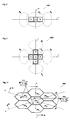
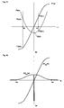
- Fig. 1 shows two flying objects TT1 and TT2 in an antenna beam B, of which the first above and the second below the boresight axis bx.
- E. Brookner, op. Cit., Chapter 5, pages 323 - 330 the spatial position of a Flying object can no longer be determined precisely as soon as a second flying object is in the same Radar steel is located.
- the phase of the resulting difference signal changes compared to the single-target case regarding the sum signal.
- conventional monopulse radars deliver faulty ones Angle measurement data, provided that the targets cannot be separated by distance.
- a special case of the two-target case is the reflection of the radar echo reflected by a flying object e.g. on a water surface.
- an elevation angle error signal usually occurs which is not zero even if the boresight axis is aligned precisely with the flying object.
- a second target echo signal reflected on the water surface is received.
- the resulting signal can then neither be resolved in distance nor in angle with respect to these two signals.
- the superimposition of these two echo signals therefore gives incorrect information regarding the elevation of the target object.
- the elevation servo circuit guides the boresight axis in the wrong direction away from the target during the tracking phase.
- Radar device is an amplitude monopulse radar device, in which the conventional with four Antennae provided with feeds (see E. Brookner, op. Cit., Chapter 5, page 301, Fig. 5.1-3) is rotated by 45 ° (diamond arrangement of the antenna horns). In addition to the previously known Antenna signals (see E. Brookner, op. Cit., Chapter 5, page 301, Fig.
- cross signal Cross difference or Cross term signal
- An antenna can also be used for this method, the three antenna horns forming a triangle having.
- the crossfeed method is therefore based, among other things, on on the evaluation of a cross term signal, which is generated by difference formation of signals emitted by antenna horns, which are not all in the measurement plane and in the basic version of the crossfeed antenna Form a cross.
- the present invention is therefore based on the object of a method and a radar device to be indicated by the two flying objects regardless of their position within the radar beam can be precisely located and measured in terms of their location.
- the second signal can instead of a second flying object also a reflected signal from the first flying object.
- the method according to the invention allows the echo signals from two to be in the antenna beam flying objects resolved and for determining the position of the flying objects in azimuth and elevation be used.
- the method according to the invention is suitable as an extension for both Amplitude as for phase monopulse radar devices, as search, target tracking or secondary radar devices be used.
- Dependent on the position of the flying objects within the antenna beam This avoids measurement errors.
- the arrangement and configuration provided according to the invention the antenna antenna or partial antennas and the evaluation of the signals emitted by them can be realized with relatively little effort.
- the area of unfavorable phase positions close to 0 ° or 180 ° between a directly received and the corresponding one indirectly reflected echo signal or the signal from a second target, making the measurement unfavorable influence, is greatly reduced by the inventive method and the device. It is particularly important for search and secondary radar systems that this also applies measurement errors are completely avoided with target deposits perpendicular to the measuring axis.
- the present invention is based on the finding that at least three sub-antennas A, B and ⁇ , the signals of which are combined with one another in such a way that two of them are required to determine the placement angle of two flying objects in one dimension (measuring axis), which are simultaneously detected by the monopulse antenna linearly independent functions F1 (x), F2 (x) (x is the target position in the selected measurement dimension, e.g. azimuth), which are not influenced by lateral positions of the detected flying objects perpendicular to the measurement axis x.
- the resulting functions F1 (x) and F2 (x) (and thus the partial antennas formed, for example, by combinations of antenna elements and the combination rule for their signals) must meet certain conditions described below.
- the intended measuring axes x, y correspond to azimuth and elevation and can be perpendicular to each other. It is e.g. however, it is also possible that the intended Measuring axes x, y enclose an acute angle and neither with azimuth nor with elevation agree in terms of direction. The direction perpendicular to the first measuring axis x therefore does not have to be inevitably correspond to the direction of the second measuring axis y. In the given embodiments, unless specifically stated, the measuring axes x and y are perpendicular to each other and chosen in accordance with azimuth or elevation. The dimensions perpendicular to the measurement dimensions x and y are referred to as sx and sy below.
- the radiation diagrams have the same amplitude and phase response perpendicular to the measuring plane and the axes bx A , bx B and bx ⁇ of the sub-antennas A, B and ⁇ consequently lie in this measuring plane .
- the partial antennas A, B and ⁇ which receive beams within the measuring plane in different directions (squint beams that only have an angular difference within the measuring plane) and which have a common phase center or an identical phase response.
- the phase centers of the partial antennas A, B and ⁇ or the corresponding subarrays, the antenna beams of which are preferably transmitted in parallel, should lie on a straight line.
- the partial beams should have the same direction and directional characteristic in planes perpendicular to the measuring plane.
- the requirement for phase monopulse radar devices can be met particularly easily.
- the formation of a cross-term signal (cross difference) with signal components from antenna horns with assigned radiation directions that are not in the measurement plane can therefore be dispensed with.
- Lateral shelves (perpendicular to the measurement plane) of the flying objects TT1, TT2 therefore do not influence the measurement results obtained in relation to the measurement plane.
- the measurement is no longer impossible if one of the flying objects has the same storage in the measurement axis and perpendicular to it.
- the functions F1 (x) and F2 (x) are selected such that they are linearly independent of one another and, in the case of a single target, give signals ( F1 ACT and F2 ACT ) which are purely real or purely imaginary. Second, equations containing the in-phase and quadrature components of the two signals F1 ACT and F2 ACT , which are complex in the two-target case, and the functions F1 (x) and F2 (x) themselves, are solved with respect to the four unknowns contained therein.
- the functions for the second measuring axis y are marked accordingly ( F1 (y), F2 (y), etc.).
- the two independent functions F1 (x) and F2 (x) required to determine the position of the flying objects per measurement dimension are formed as follows:
- the signals a2 (x, sx), b2 (x, sx) and ⁇ 2 (x, sx) emitted by partial antennas A, B and ⁇ of an extended monopulse antenna are generally of the position x of a flying object with respect to the measurement dimension and the position perpendicular thereto sx dependent.
- the radiation diagrams of the partial antennas A, B and ⁇ have the same amplitude and phase response perpendicular to the measurement plane.
- the antenna function ⁇ 2 (x, sx) was used arbitrarily for standardization. This partial antenna function ⁇ 2 (x, sx) and ⁇ (x) is therefore referred to as the reference function and the partial antenna ⁇ as the reference antenna.
- a normalization of the partial antenna functions a (x) and b (x) with ⁇ (x) results in quotients A (x) and B (x), which are independent of deposits in the dimension sx:
- a (x) a (x) / ⁇ (x)
- B (x) b (x) / ⁇ (x)
- phase positions of the partial antenna functions a (x) and b (x) are related to the phase position of the reference function ⁇ (x):
- a (x), ⁇ a (x) and ⁇ b (x) and the phases ⁇ (x), ⁇ a (x) as well as ⁇ b (x) or ⁇ (x) and ⁇ (x) depend on the target position in the measuring axis x.
- Equation sets G12 and G22 result in functions with poles that are unfavorable for further processing. Equation theorem G11 and equation theorem G21 are therefore of practical importance. Either set of equations G11 or set of equations G21 must therefore be fulfilled for each of the functions F1 (x) and F2 (x).
- the weighting factors R, S, T, E, G and H can be freely selected for the functions F1 (x) and F2 (x) in the following formula, in which the affiliation to the amplitude monopulse method is indicated by the index A.
- Mp A ( x ) R * ⁇ a ( x ) ⁇ ⁇ ( x ) + S + T * ⁇ b ( x ) ⁇ ⁇ ( x ) E * ⁇ a ( x ) ⁇ ⁇ ( x ) + G + H * ⁇ b ( x ) ⁇ ⁇ ( x )
- F2 A ( x ) R * ( ⁇ a ( x ) ⁇ ⁇ ( x ) + ⁇ a (- x ) ⁇ ⁇ (- x ) - 2 * ⁇ a (0) ⁇ (0) ) E * ( ⁇ a ( x ) ⁇ ⁇ ( x ) + ⁇ a (- x ) ⁇ ⁇ (- x ) ) + G
- the functions F1 (x) and F2 (x), on the other hand, are always independent of one another if one (eg F1 (x)) is odd and the other ( F2 (x)) is even. Since of the two functions F1 A (x) and F2 A (x) specified for the amplitude monopulse method, for example, the first is odd and the second is even, in addition to claims 1 and 2, requirement 3 mentioned above for independence of functions F1 A (x) and F2 A (x) fulfilled. Since the functions F1 A (x) and F2 A (x) have the same denominator, requirement 4 is also fulfilled.
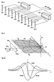
- FIG. 7 shows an extended phase monopulse antenna PA1, which can be used particularly advantageously for the method according to the invention, since antenna elements AE of the phased array antenna PA can be selected without difficulty in such a way that partial antennas ⁇ , C, D are formed, the Phase centers lie on a straight line and their main radiation axes tax C , tax D and tax ⁇ , as shown in FIG. 8, lie parallel to one another in one plane.
- the zones Z ⁇ , Z C , and Z D whose phase centers are to be arranged according to the invention, are selected, for example, as in FIG. 7.
- the antenna PA1 is used, for example, to measure objects in elevation.
- additional partial antennas A, B or zones Z A , Z B are to be provided, the phase centers of which lie on a further straight line, which is arranged, for example, orthogonally to the first straight line on which the phase centers of the partial antennas ⁇ , C, D lie.
- the phase centers of the partial antennas A and B should also have the same distance from the phase center of the central antenna ⁇ .
- those of partial antennas have one Phase monopulse radar device received signals from outside the boresight axis flying object TT were reflected, unequal phases and same amplitudes.
- the difference signals are related on the sum signals a phase difference of 0 ° for amplitude monopulse or 90 ° for Phase monopulse. This fact is also in the formation of the formulas for eleven Monopulse radars to be considered accordingly.
- ⁇ a (x) ⁇ a (-x)
- ⁇ b (x) ⁇ b (-x)
- ⁇ (x) ⁇ (-x)
- ⁇ (x) - ⁇ (x).
- This condition is met if the partial antenna ⁇ and thus its phase center is exactly in the middle between the phase centers the partial antennas A and B is arranged.
- These conditions can be compared to Amplitude monopulse method, in which all sub-antennas A, B and ⁇ the same phase center should have, are relatively easy to meet.
- weighting factors E, G, H, R, S and T in the formulas 8a to 8d either G11 or G21 is satisfied.
- the index ⁇ is used.
- the odd function F1 ⁇ (x) and the even function F2 ⁇ (x) are linearly independent of each other.
- the antenna function pair formed (F1 A (x), F2 A (x) or F1 ⁇ (x), F2 ⁇ (x)), which meets the requirements 1, 2, 3 and 4, is measured for the single-target case.
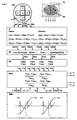
- the determined functional areas are stored in a memory. Function curves measured for, for example, fixed antenna functions F1 (x), F2 (x) are shown in FIG. 10.
- the values of the antenna functions F1 (x), F2 (x) at the locations x1 and x2 where the flying objects TT1, TT2 are located are also shown.
- R1, S1 and T1 denote the coefficients R, S and T selected for the first function F1 (x).
- a target from direction x generates the field strength ex.
- the signal values F1 ACT and F2 ACT determined in the radar device according to these formulas become complex and no longer correspond to the values recorded for the single-target case.
- quadrature signal components F1q ACT and F2q ACT also occur, which must be taken into account for the correct position determination of the two flying objects. The resulting signals are derived below:
- the signals with the field strengths ex1 and ex2 are received from two destinations from the directions x1 and x2, which are phase-shifted by the angle ⁇ and have different signal strengths by the factor ⁇ .
- F1 (x) and F2 (x) are now broken down into their real and imaginary components (p and q):
- F1 (x1) F1p (x1) + j * F1q (x1)
- F1 (x2) F1p (x2) + j * F1q (x2)
- F2 (x1) F2p (x1) + j * F2q (x1)
- F2 (x2) F2p (x2) + j * F2q (x2)
- F 12 (x1, x2, ⁇ , ⁇ ) and F22 (x1, x2, ⁇ , ⁇ ) therefore applies:
- F 1 2 ( x 1, x 2, ⁇ , ⁇ ) ( F 1 p ( x 1) + j * F 1 q ( x 1)) + N * e j ⁇ * ( F 1 p ( x 2) + j * F 1 q ( x 2)) 1 + N * e j ⁇
- F 22 ( x 1, x 2, ⁇ , ⁇ ) ( F 2 p ( x 1) + j * F 2 q ( x 1)) + N * e j ⁇ * ( F 2 p ( x 2) + j * F 2 q ( x 2)) 1 + N * e j ⁇
- the real and imaginary parts correspond to F12p (x1, x2, ⁇ , ⁇ ), F12q (x1, x2, ⁇ , ⁇ ), F22p ( x1, x2, ⁇ , ⁇ ) and F12q (x1, x2, ⁇ , ⁇ ) now the actually measured (or formed in quadrature channels) signal values F1p ACT , F2p ACT , F1q ACT and F2q ACT , which are obtained from the sub-antennas A , B, ⁇ are emitted and correspondingly weighted and combined signals are formed.
- the signal values F1p ACT , F2p ACT , F1q ACT and F2q ACT are therefore equal to the real and imaginary parts F12p (x1, x2, ⁇ , ⁇ ), F12q (x1, x2, ⁇ , ⁇ ), F22p (x1, x2, ⁇ , ⁇ ) and F22q (x1, x2, ⁇ , ⁇ ) of the functions F12 (x1, x2, ⁇ , ⁇ ) and F22 (x1, x2, ⁇ , ⁇ ).
- F 1 p ACT F 1 ( x 1) + N * cos ⁇ * ( F 1 ( x 1) + F 1 ( x 2)) + N 2 * F 1 ( x 2) 1 + 2 * N * cos ⁇ + N 2
- F 1 q ACT ( F 1 ( x 2) - F 1 ( x 1)) * N * sin ⁇ 1 + 2 * N * cos ⁇ + N 2
- F 1 p ACT j * ( F 1 ( x 2) - F 1 ( x 1)) * N * sin ⁇ 1 + 2 * N * cos ⁇ + N 2
- F 1 q ACT - j * F 1 ( x 1) + N * cos ⁇ * ( F 1 ( x 1) + F 1 ( x 2)) + N 2 * F 1 ( x 2) 1 + 2 * N * cos ⁇ + N 2
- F 2 p ACT F 2 ( x 1) + N * cos ⁇ * ( F 2 ( x 1) + F 2 ( x 2)) + N 2 * F 2 ( x 2) 1 + 2 * N * cos ⁇ + N 2
- F 2 q ACT ( F 2 ( x 1) - F 2 ( x 2)) * N * sin ⁇ 1 + 2 * N * cos ⁇ + N 2
- the values F1 A p ACT , F1 A q ACT , F2 A p ACT and F2 A q ACT or F1 ⁇ p ACT , F1 ⁇ q ACT , F2 ⁇ p ACT and F2 ⁇ q ACT are measured.
- the value of x for the target closer to the boresight axis can also be determined approximately from the formulas 120p or 120q derived from the formulas 119a, 119b, in that the value for F2 A (x) or F2 ⁇ (x) is equal to F2 A (0 ) or equal to F2 ⁇ (0).
- the method according to the invention therefore allows, in comparison to the classic monopulse method Even in the case of a single target, the exact determination of the target data, since x, y each for determining the target deposits two equations are available.
- Fig. 4 shows a section through a parabolic antenna
- the same procedure can also be carried out for the second measuring axis (elevation).
- the centrally located partial antenna ⁇ can serve as a reference antenna for both measurement dimensions.
- the main beam direction of the partial antenna ⁇ lies together with the main beam directions of the partial antennas A and B in a first measuring plane and together with the axes of the partial antennas C and D in a second measurement plane, which is preferably orthogonal to the eleventh plane.
- partial antennas consisting of antenna elements AE1,..., AEn can also be used advantageously for the amplitude monopulse method.
- the antenna elements AE1, ..., AEn are to be arranged and connected to existing networks AFa and AFb in such a way that the main radiation directions of the partial antennas are in turn aligned as shown in FIG. 6.
- the signal a (x) is emitted by the network AFa, the signal b (x) by the network AFb and the signal ⁇ (x) by the antenna element AE6.
- the weighting and combination of the antenna signals a (x), b (x) and ⁇ (x) takes place, for example, in a subsequent network.
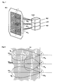
- FIG. 9 shows a monopulse radar device which has either an antenna HA2 or an antenna PA, one for summing and difference formation and for weighting the antenna signals a (x), b (x), ⁇ (x), c (x) and d ( x)
- the network AF provided, a division stage NM provided for forming the quotient, which normally also contains the receiving channels, a quadrature demodulator QG provided for forming quadrature components and a processor PROC connected to a memory unit MEM.
- Networks AF and demodulator QG are known, for example, from E. Brookner, loc. Cit., Chapter 5.4.5, page 316 (Comparators) and Chapter 5.6.2, page 322.
- the quotients according to formulas 16 and 17, which are independent of the incoming signal strength, can be formed in division level NM.
- the processes running in the stages AF, NM, QG can also be carried out in the processor PROC.
- the signals emitted by the partial antennas A, B, ⁇ , C, D are amplified, demodulated and digitized and fed to the processor PROC.
- the processor PROC preferably works according to the pipeline method and therefore has a high read cycle. However, reading out the data may be delayed by a few clock cycles.
- the stored functions F1, F2 are preferably approximated in a first step by third degree polynomials and the equations are solved analytically. The solutions found in this way are preferably used as first approximate values for an iterative process.
- the radar device can be designed as an expanded amplitude or as a phase monopulse radar device and is accordingly equipped with one of the antennas shown in FIG. 2, 3, 5 or 7 (for example, home antenna HA2 or phased array antenna PA). Mistake.
- the signals a (x), b (x) and ⁇ (x) (or c (y), d (y) and ⁇ (y) emitted by the partial antennas A, B, ⁇ , C, D are ) individually weighted and added for numerators and denominators of formulas 16 and 17 (or 101a, 101b).
- the signals are divided according to the formulas 16 and 17 (or 101a, 101b), so that at the output of this stage the signals F12 and F22 correspond to signals which are present in the demodulator QG in in-phase components F1p ACT , F2p ACT and divided into quadrature fractions F1q ACT , F2q ACT .
- the signals F1p ACT , F1q ACT , F2p ACT and F2q ACT determined by these measures in the radar device are sampled according to the signal bandwidth and fed to the processor PROC, which according to formula 119a and 119b uses the ones stored in the memory MEM for the single-target case measured antenna functions F1 (x), F2 (x) determines the solutions x1 and x2 of equations 119a and 119b.
- suitable functions F1 (x), F2 (x) can be defined and the corresponding antenna beams can then be determined according to Formula 1000.
- array antennas in which signal components are to be obtained from all antenna elements if possible, it makes more sense to define and optimize lighting functions Js , J01 and J02 and to use these to determine functions F1 (x) and F2 (x).
- the transition from the lighting function Js ; J01 or J02 which determines the weighting of the elementary signals of an array antenna as a function of the location lx on the array, for the corresponding antenna functions Fs (x), F01 (x) and F02 (x) is carried out by the founer transformation.
- Illumination functions Js (lx), J01 (lx) and J02 (lx) are used to scan or measure the wave fronts arriving from the measured targets, which are curved in the case of a multi-target case. If only a spherical or approximately flat wavefront originating from a target were to be measured, its inclination with respect to the radar antenna could be determined using an illumination function in accordance with the classic monopulse method (inclination monopulse). To measure the curvature of a wavefront originating from two targets, an additional lighting function is required which is linearly independent of the first. The extension of the classic monopulse method by introducing an additional antenna function is referred to below as the curvature monopulse method.
- the lighting function J02 (lx) is optimized for a measurement of the field curvature.
- antenna functions F1 (x), F2 (x) are achieved, by means of which the resolution of two targets with regard to position, signal power and signal phase is achieved. After determining the antenna functions F1 (x), F2 (x), the method according to the invention is carried out as already described above.
- the first odd and the second is preferably chosen.
- the course of the odd lighting function is point-symmetrical with respect to the origin of the coordinate system.
- the course of the straight lighting function is axisymmetric with respect to the ordinate of the coordinate system.
- the illumination function Js (lx) which changes into the sum or reference function Fs (x) by applying the Fourier transformation, is to be selected such that the ratio F01 (x) / Fs (x) or F02 (x) / Fs (x ) remains constant for shelves perpendicular to the measuring axis. This can be achieved, for example, if, in addition to fulfilling the above-mentioned conditions, the lighting functions J01s (lsx), J02s (lsx) and Jss (lsx) have functional profiles over the aperture of the array antenna perpendicular to the measuring axis, which differ only in a proportionality factor.
- the antenna functions resulting from the two-dimensional lighting functions j01 (lx, lsx), j02 (lx, lsx) js (lx, lsx) by Fourier transformation are f01 (lx, lsx), f02 (lx, lsx) fs (lx, lsx) .
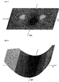
- FIG. 11 shows the two-dimensional pattern of the antenna function of the cross term signal (diagonal difference signal) known from Sherman, SM, Monopulse Principles and Techniques, Artech House, Norwood, MA, 1984, page 341, FIG. 12.2-1.
- the cross term signal (diagonal difference signal) known from Sherman, SM, Monopulse Principles and Techniques, Artech House, Norwood, MA, 1984, page 341, FIG. 12.2-1.
- the values of this cross term function change as a function of target positions x in the measurement plane and as a function of target positions sx perpendicular to the measurement plane.
- the cross term function known from the prior art therefore does not meet requirement 3 'according to the invention.
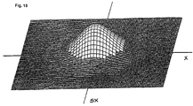
- FIG. 13 shows the two-dimensional pattern of an illumination function defined according to the invention for a function which can be used according to the invention (for example for FIG. 10, function F2 (x)).
- lx is the location on the antenna measured from the center and lxo is the distance from the edge to the center of the antenna.
- the function W2 is ideal for measuring the curvature of a field. However, it has strong side lobes that are intolerable. The lighting function J02 should therefore be approximated to the function W2 until the side peaks reach the still tolerable dimension. It is now: the reference power of the curvature beam and the measurement performance.
- lx0 is the location on the aperture where the excitation amplitude of the Gaussian function has decreased by 1 / e 1 ⁇ 2 or the excitation power by 1 / e compared to the value in the center.
- the method according to the invention can be used particularly advantageously in connection with radar devices which are suitable for carrying out the sidelobe suppression (SLS) method, which is described, for example, in Richard C. Johnson, Antenna Engineering Handbook, Mc Graw-Hill Book Company, New York 1993, third Edition, chapter 33, pages 33-6 to 33-8.
- SLS sidelobe suppression
- a gap pattern (Notch-Pattem) is used, which results from the sum pattern by the phase inversion of the elementary signals from antenna elements, which is in the middle of the Form a column antenna perpendicular to the measuring axis.
- This gap pattern is similar to the pattern of the lighting function J02 (lx) defined according to the invention shown in FIG. 13.
- the illumination function of the SLS array antenna corresponding to the gap pattern corresponds, after Fourier transformation and normalization with the sum function, to a straight function F2 (x) which can be used according to the invention.
- a radar system which is suitable for carrying out the sidelobe suppression (SLS) method can therefore be expanded to a system suitable for carrying out the method according to the invention with practically no manual changes to the antenna.
- the two methods provided in a radar system for suppressing target signals which are received via side lobes and for resolving two targets which are detected by the main lobes therefore complement one another in an ideal manner.
- the target directions determined according to the method according to the invention can also be used for control purposes the antenna can be used.
- the transmission diagram is set so that with respect to the direction of a Interference signal or a target to be hidden, if possible, no signal transmitted or received becomes.
- the data available in the processor for determining the target positions x1, x2 can also be used for determining the phase angle den between the signals arriving from direction x1, y1 and x2, y2.
- the angle ⁇ can be clearly determined on the basis of the values of sin ⁇ and cos ⁇ . Likewise can the angle ⁇ also with the data of the curvature channel (replace F1 in the formulas above with F2) as well as the data used in the phase monopulse method. By measurement of the angle ⁇ can distinguish real two-target cases from reflection cases as well as unfavorable phase positions are recognized, in which the angle ⁇ becomes close to zero or close to ⁇ .
- Phase differences ⁇ close to zero or close to ⁇ can e.g. by changing the transmission frequency be avoided.
- the phase changes between two measurements are typical about a hundred times smaller than in two-target cases where the transponder have different transmission frequencies from two destinations. This allows reflections from real A distinction is made between two target cases.
- Two targets can also have a difference frequency (Beat) can be assigned, which allows this target pair to be restored at a later time to identify.
- Beat difference frequency
- the power ratios L A 1, L A 2 can also be determined using the data of the curvature channel and the data used in the phase monopulse method. Based on the data obtained, the goals can be marked and then more easily followed. If two targets are detected by the radar system according to the invention (see FIG. 9), their angle data x1, y1 and x2, y2 can be determined according to the invention. If the targets swap their positions at a later moment, for example, this is not recognized if only the angle data x1, y1 and x2, y2 are determined. If, however, the power ratios L A 1, L A 2 were determined before the swapping, the targets can be clearly identified again even after a transmission interruption.
- the effective antenna-independent target-specific services are determined the directional characteristic of the sum diagram in the direction of the target in question with the calibration direction as a correction factor.
- the determination of the performance ratios L A 1, L A 2 and the target-specific benefits can be used extremely advantageously for various purposes.
- the goals can be labeled as described above, making it much easier to pursue these goals.
- the reflection factor can also be determined for mirrored targets. It can also be determined whether there is a one-target or a two-target case. If the division of the performance ratios L A 1, L A 2 goes towards zero or ⁇ , there is a single-target case. If a threshold value close to zero or ⁇ is undershot or exceeded, the procedure for determining the target data according to the formulas (Formula 121) is therefore used for the single-target case.
- the determination of the power ratios L A 1, L A 2 is also advantageous when measuring the target in two dimensions.
- target deposits x1, x2, y1 and y2 can be determined by the method according to the invention. It is initially unclear which target shelves are to be combined. Is the first target at x1, y2 and the second target at x2, y1 or is the first target at x1, y1 and the second target at x2, y2?
- the performance measurement can now be used to determine which pair of target shelves x1, y1; x1, y2 or x2, y1; x2, y2 has at least approximately the same power ratios L A 1 and L A 2 and belongs to a target pair and not to a phantom pair. Of particular importance is the determination of the performance ratios L A 1, L A 2 for the suppression or separation of interference signals (defruiting, degarbeling). The underlying individual signals can thus be identified.
- the honeycomb antenna provided with seven subarrays shown in FIG. 17 can also be used advantageously WA, which is able to measure two targets in three coplanar dimensions x, y, z and based on the measured values x1, x2, y1, y2, z1, z2.
- the three measuring axes x, y, z run through the phase centers pz5, pz ⁇ , pz6; pz3, pz ⁇ , pz4 or pz1, pz ⁇ , pz2 of three subarrays each and preferably intersect in the phase center pz ⁇ of the central subarray ⁇ .
- Phantom- or ghost images can be complete by using the measurements from the third measurement dimension be switched off without taking into account the performance of the individual signals are. This gives the advantage that clear location is also possible if the performance ratio both target echo signals are the same.
- the destinations TT1, TT2 shown in FIG. 17 are present Places that are identified by measurement values from all three measurement dimensions.
- the target data can be measured using the method according to the invention only with respect to position x1, y1; x2, y2, only with respect to phase ⁇ or only with regard to the power ratios L A 1, L A 2, but also in any combination.
Landscapes
- Engineering & Computer Science (AREA)
- Radar, Positioning & Navigation (AREA)
- Remote Sensing (AREA)
- Computer Networks & Wireless Communication (AREA)
- Physics & Mathematics (AREA)
- General Physics & Mathematics (AREA)
- Radar Systems Or Details Thereof (AREA)
- Variable-Direction Aerials And Aerial Arrays (AREA)
Applications Claiming Priority (4)
| Application Number | Priority Date | Filing Date | Title |
|---|---|---|---|
| CH3590/95 | 1995-12-19 | ||
| CH359095 | 1995-12-19 | ||
| CH359095 | 1995-12-19 | ||
| PCT/CH1996/000124 WO1997022890A1 (de) | 1995-12-19 | 1996-04-09 | Verfahren und amplituden- oder phasen-monopulsradargerät zur ortung von flugobjekten |
Publications (2)
| Publication Number | Publication Date |
|---|---|
| EP0809811A1 EP0809811A1 (de) | 1997-12-03 |
| EP0809811B1 true EP0809811B1 (de) | 2001-07-11 |
Family
ID=4259267
Family Applications (1)
| Application Number | Title | Priority Date | Filing Date |
|---|---|---|---|
| EP96907242A Expired - Lifetime EP0809811B1 (de) | 1995-12-19 | 1996-04-09 | Verfahren und amplituden- oder phasen-monopulsradargerät zur ortung von flugobjekten |
Country Status (7)
| Country | Link |
|---|---|
| US (1) | US5784022A (da) |
| EP (1) | EP0809811B1 (da) |
| AT (1) | ATE203109T1 (da) |
| CA (1) | CA2214285C (da) |
| DE (1) | DE59607276D1 (da) |
| DK (1) | DK0809811T3 (da) |
| WO (1) | WO1997022890A1 (da) |
Cited By (1)
| Publication number | Priority date | Publication date | Assignee | Title |
|---|---|---|---|---|
| US10514443B2 (en) * | 2016-09-28 | 2019-12-24 | Robert Bosch Gmbh | Method for evaluating radar radiation, and radar apparatus |
Families Citing this family (31)
| Publication number | Priority date | Publication date | Assignee | Title |
|---|---|---|---|---|
| EP0942294A3 (de) * | 1998-03-09 | 2000-06-07 | Siemens Schweiz AG (Siemens Suisse SA) (Siemens Svizzera SA) Siemens Switzerland Ltd) | Verfahren zur Seitenkeulenunterdrückung und Amplituden- oder Phasen-Monopulsradargerät |
| SE513939C2 (sv) * | 1998-06-24 | 2000-11-27 | Combitech Traffic Syst Ab | Anordning för positionsbestämning medelst radiovågor |
| US6388755B1 (en) * | 1998-12-03 | 2002-05-14 | Advanced Optical Technologies, Inc. | Wireless position and orientation detecting system |
| US7612716B2 (en) | 1999-03-05 | 2009-11-03 | Era Systems Corporation | Correlation of flight track data with other data sources |
| US7667647B2 (en) | 1999-03-05 | 2010-02-23 | Era Systems Corporation | Extension of aircraft tracking and positive identification from movement areas into non-movement areas |
| US7570214B2 (en) | 1999-03-05 | 2009-08-04 | Era Systems, Inc. | Method and apparatus for ADS-B validation, active and passive multilateration, and elliptical surviellance |
| US7777675B2 (en) | 1999-03-05 | 2010-08-17 | Era Systems Corporation | Deployable passive broadband aircraft tracking |
| US7739167B2 (en) | 1999-03-05 | 2010-06-15 | Era Systems Corporation | Automated management of airport revenues |
| US7782256B2 (en) | 1999-03-05 | 2010-08-24 | Era Systems Corporation | Enhanced passive coherent location techniques to track and identify UAVs, UCAVs, MAVs, and other objects |
| US8203486B1 (en) | 1999-03-05 | 2012-06-19 | Omnipol A.S. | Transmitter independent techniques to extend the performance of passive coherent location |
| US7889133B2 (en) | 1999-03-05 | 2011-02-15 | Itt Manufacturing Enterprises, Inc. | Multilateration enhancements for noise and operations management |
| US8446321B2 (en) | 1999-03-05 | 2013-05-21 | Omnipol A.S. | Deployable intelligence and tracking system for homeland security and search and rescue |
| US7908077B2 (en) | 2003-06-10 | 2011-03-15 | Itt Manufacturing Enterprises, Inc. | Land use compatibility planning software |
| US6404379B1 (en) * | 2000-06-29 | 2002-06-11 | Lockheed Martin Corporation | Matrix monopulse ratio radar processor for two target azimuth and elevation angle determination |
| US6356231B1 (en) * | 2000-06-29 | 2002-03-12 | Lockheed Martin Corporation | Monopulse radar processor for resolving two sources |
| FR2817973A1 (fr) * | 2000-12-13 | 2002-06-14 | Imra Europe Sa | Methode de detection et de positionnement d'objets basee sur deux etapes de formation numerique de faisceaux d'un reseau phase de capteurs |
| US6759983B2 (en) | 2001-03-28 | 2004-07-06 | Strategic Analysis, Inc. | Method and device for precise geolocation of low-power, broadband, amplitude-modulated signals |
| US6597312B1 (en) | 2002-01-30 | 2003-07-22 | Northrop Grumman Corporation | Phased array antenna system generating multiple beams having a common phase center |
| JP2005156337A (ja) * | 2003-11-26 | 2005-06-16 | Hitachi Ltd | 車載用レーダ装置 |
| DE102004004492A1 (de) * | 2004-01-29 | 2005-08-18 | Robert Bosch Gmbh | Radarsystem für Kraftfahrzeuge |
| US7965227B2 (en) | 2006-05-08 | 2011-06-21 | Era Systems, Inc. | Aircraft tracking using low cost tagging as a discriminator |
| US7821443B2 (en) * | 2008-02-12 | 2010-10-26 | Infineon Technologies Ag | Dual mode radar methods and systems |
| JP2009265007A (ja) * | 2008-04-28 | 2009-11-12 | Hitachi Ltd | 移動体用レーダ及び平面アンテナ |
| JP5811931B2 (ja) * | 2012-04-04 | 2015-11-11 | トヨタ自動車株式会社 | 位相モノパルスレーダ装置 |
| DE102012016475B4 (de) * | 2012-08-17 | 2022-09-08 | Hensoldt Sensors Gmbh | Verfahren zur Richtungspeilung nach dem Monopulsprinzip |
| DE102014104273B4 (de) * | 2014-03-26 | 2024-08-14 | Symeo Gmbh | Verfahren in einem Radarsystem, Radarsystem bzw. Vorrichtung eines Radarsystems |
| JP6415386B2 (ja) * | 2015-05-28 | 2018-10-31 | 三菱電機株式会社 | 測角装置、レーダ装置、及び測角方法 |
| JP6877438B2 (ja) | 2016-01-04 | 2021-05-26 | シメオ ゲゼルシャフト ミット ベシュレンクテル ハフツング | レーダシステムにおける位相ノイズに起因する干渉を低減するための方法及びシステム |
| DE102017110063A1 (de) * | 2017-03-02 | 2018-09-06 | Friedrich-Alexander-Universität Erlangen-Nürnberg | Verfahren und Vorrichtung zur Umfelderfassung |
| RU2696095C1 (ru) * | 2019-02-20 | 2019-07-31 | Акционерное общество "Концерн "Созвездие" | Способ двухмерного моноимпульсного пеленгования источников радиоизлучений |
| CN112083382B (zh) * | 2020-09-15 | 2022-08-02 | 四川九洲空管科技有限责任公司 | 一种高精度小型相控阵二次雷达方位补偿计算方法 |
Family Cites Families (2)
| Publication number | Priority date | Publication date | Assignee | Title |
|---|---|---|---|---|
| CH592887A5 (da) * | 1975-05-22 | 1977-11-15 | Siemens Ag Albis | |
| CH629898A5 (de) * | 1978-02-09 | 1982-05-14 | Siemens Ag Albis | Anordnung zur verbesserung der winkelvermessung bei einem folgeradar. |
-
1996
- 1996-04-09 EP EP96907242A patent/EP0809811B1/de not_active Expired - Lifetime
- 1996-04-09 WO PCT/CH1996/000124 patent/WO1997022890A1/de not_active Ceased
- 1996-04-09 US US08/817,703 patent/US5784022A/en not_active Expired - Fee Related
- 1996-04-09 DK DK96907242T patent/DK0809811T3/da active
- 1996-04-09 CA CA002214285A patent/CA2214285C/en not_active Expired - Fee Related
- 1996-04-09 AT AT96907242T patent/ATE203109T1/de not_active IP Right Cessation
- 1996-04-09 DE DE59607276T patent/DE59607276D1/de not_active Expired - Fee Related
Cited By (1)
| Publication number | Priority date | Publication date | Assignee | Title |
|---|---|---|---|---|
| US10514443B2 (en) * | 2016-09-28 | 2019-12-24 | Robert Bosch Gmbh | Method for evaluating radar radiation, and radar apparatus |
Also Published As
| Publication number | Publication date |
|---|---|
| CA2214285A1 (en) | 1997-06-26 |
| US5784022A (en) | 1998-07-21 |
| WO1997022890A1 (de) | 1997-06-26 |
| EP0809811A1 (de) | 1997-12-03 |
| DK0809811T3 (da) | 2001-10-22 |
| CA2214285C (en) | 2001-06-05 |
| ATE203109T1 (de) | 2001-07-15 |
| DE59607276D1 (de) | 2001-08-16 |
Similar Documents
| Publication | Publication Date | Title |
|---|---|---|
| EP0809811B1 (de) | Verfahren und amplituden- oder phasen-monopulsradargerät zur ortung von flugobjekten | |
| DE102009046499B4 (de) | Radarvorrichtung | |
| DE60302379T2 (de) | Radarverarbeitungssystem und Verfahren zur Erkennung und Überwachung von Zielen | |
| DE102010002474B4 (de) | Radarvorrichtung zum Unterdrücken von Wirkungen von Gitterkeulen bei der Erfassung einer Richtung eines Ziels auf der Grundlage einer Phasendifferenz zwischen empfangenen reflektierten Wellen | |
| DE112008000513B4 (de) | Elektronisch abtastendes Radarsystem | |
| EP0942294A2 (de) | Verfahren zur Seitenkeulenunterdrückung und Amplituden- oder Phasen-Monopulsradargerät | |
| DE102011088045B4 (de) | Phased-Array-Antenne und Phasenkalibrierungsverfahren | |
| DE2650832C2 (de) | Impulsradargerät | |
| DE60109990T2 (de) | Monopuls-Radar-Prozessor zur Bestimmung des Azimuth- und Elevationswinkels zweier Ziele über eine Matrix von Amplitudenverhältnissen | |
| DE60027418T2 (de) | Verfahren zur anzeige ausser-axialer signale für monopulsradar | |
| DE102018207686A1 (de) | MIMO-Radarsensor für Kraftfahrzeuge | |
| DE102008001467A1 (de) | Mehrstrahlradarsensor | |
| DE102018200765A1 (de) | FMCW-Radarsensor | |
| DE69106206T2 (de) | Rundstrahl-Funkpeilantennensystem. | |
| DE69314412T2 (de) | Antenne mit Nebenkeulenunterdrückung | |
| DE2306407B2 (de) | Antennensystem hoher Winkelauflösung für Radargeräte mit getrennten Sende- und Empfangsantennen | |
| WO2019158251A1 (de) | Antennenanordnung für einen radarsensor | |
| DE3136625C1 (de) | Großbasispeiler | |
| DE102021201073A1 (de) | MIMO-Radarsensor | |
| DE2929254C2 (de) | Antennensystem zur Peilung einer Mikrowellen-Signalquelle | |
| EP1500952A2 (de) | Verfahren zur Winkelbestimmung bei Mehrzielszenarien für Mehrkeulen-Monopulsradar | |
| DE2226435A1 (de) | Radiointerferometer | |
| DE60133222T2 (de) | Interferometische synthetische sonarantenne | |
| EP4139706A1 (de) | Radar-verfahren und radar-system zur phasenkohärenten auswertung | |
| EP0108094B1 (de) | Peilanordnung |
Legal Events
| Date | Code | Title | Description |
|---|---|---|---|
| PUAI | Public reference made under article 153(3) epc to a published international application that has entered the european phase |
Free format text: ORIGINAL CODE: 0009012 |
|
| AK | Designated contracting states |
Kind code of ref document: A1 Designated state(s): AT BE CH DE DK ES FI FR GB GR IE IT LI LU MC NL PT SE |
|
| 17P | Request for examination filed |
Effective date: 19971229 |
|
| 17Q | First examination report despatched |
Effective date: 19981012 |
|
| GRAG | Despatch of communication of intention to grant |
Free format text: ORIGINAL CODE: EPIDOS AGRA |
|
| GRAG | Despatch of communication of intention to grant |
Free format text: ORIGINAL CODE: EPIDOS AGRA |
|
| GRAH | Despatch of communication of intention to grant a patent |
Free format text: ORIGINAL CODE: EPIDOS IGRA |
|
| GRAH | Despatch of communication of intention to grant a patent |
Free format text: ORIGINAL CODE: EPIDOS IGRA |
|
| GRAA | (expected) grant |
Free format text: ORIGINAL CODE: 0009210 |
|
| AK | Designated contracting states |
Kind code of ref document: B1 Designated state(s): AT BE CH DE DK ES FI FR GB GR IE IT LI LU MC NL PT SE |
|
| PG25 | Lapsed in a contracting state [announced via postgrant information from national office to epo] |
Ref country code: IT Free format text: LAPSE BECAUSE OF FAILURE TO SUBMIT A TRANSLATION OF THE DESCRIPTION OR TO PAY THE FEE WITHIN THE PRE;WARNING: LAPSES OF ITALIAN PATENTS WITH EFFECTIVE DATE BEFORE 2007 MAY HAVE OCCURRED AT ANY TIME BEFORE 2007. THE CORRECT EFFECTIVE DATE MAY BE DIFFERENT FROM THE ONE RECORDED.SCRIBED TIME-LIMIT Effective date: 20010711 Ref country code: IE Free format text: LAPSE BECAUSE OF FAILURE TO SUBMIT A TRANSLATION OF THE DESCRIPTION OR TO PAY THE FEE WITHIN THE PRESCRIBED TIME-LIMIT Effective date: 20010711 Ref country code: FI Free format text: LAPSE BECAUSE OF FAILURE TO SUBMIT A TRANSLATION OF THE DESCRIPTION OR TO PAY THE FEE WITHIN THE PRESCRIBED TIME-LIMIT Effective date: 20010711 |
|
| REF | Corresponds to: |
Ref document number: 203109 Country of ref document: AT Date of ref document: 20010715 Kind code of ref document: T |
|
| REG | Reference to a national code |
Ref country code: CH Ref legal event code: EP |
|
| GBT | Gb: translation of ep patent filed (gb section 77(6)(a)/1977) |
Effective date: 20010711 |
|
| REF | Corresponds to: |
Ref document number: 59607276 Country of ref document: DE Date of ref document: 20010816 |
|
| REG | Reference to a national code |
Ref country code: IE Ref legal event code: FG4D Free format text: GERMAN |
|
| PG25 | Lapsed in a contracting state [announced via postgrant information from national office to epo] |
Ref country code: PT Free format text: LAPSE BECAUSE OF FAILURE TO SUBMIT A TRANSLATION OF THE DESCRIPTION OR TO PAY THE FEE WITHIN THE PRESCRIBED TIME-LIMIT Effective date: 20011011 |
|
| PG25 | Lapsed in a contracting state [announced via postgrant information from national office to epo] |
Ref country code: GR Free format text: LAPSE BECAUSE OF FAILURE TO SUBMIT A TRANSLATION OF THE DESCRIPTION OR TO PAY THE FEE WITHIN THE PRESCRIBED TIME-LIMIT Effective date: 20011012 |
|
| REG | Reference to a national code |
Ref country code: DK Ref legal event code: T3 |
|
| ET | Fr: translation filed | ||
| REG | Reference to a national code |
Ref country code: GB Ref legal event code: IF02 |
|
| PG25 | Lapsed in a contracting state [announced via postgrant information from national office to epo] |
Ref country code: ES Free format text: LAPSE BECAUSE OF FAILURE TO SUBMIT A TRANSLATION OF THE DESCRIPTION OR TO PAY THE FEE WITHIN THE PRESCRIBED TIME-LIMIT Effective date: 20020131 |
|
| PG25 | Lapsed in a contracting state [announced via postgrant information from national office to epo] |
Ref country code: MC Free format text: LAPSE BECAUSE OF NON-PAYMENT OF DUE FEES Effective date: 20020409 Ref country code: LU Free format text: LAPSE BECAUSE OF NON-PAYMENT OF DUE FEES Effective date: 20020409 Ref country code: GB Free format text: LAPSE BECAUSE OF NON-PAYMENT OF DUE FEES Effective date: 20020409 Ref country code: AT Free format text: LAPSE BECAUSE OF NON-PAYMENT OF DUE FEES Effective date: 20020409 |
|
| PG25 | Lapsed in a contracting state [announced via postgrant information from national office to epo] |
Ref country code: SE Free format text: LAPSE BECAUSE OF NON-PAYMENT OF DUE FEES Effective date: 20020410 |
|
| PG25 | Lapsed in a contracting state [announced via postgrant information from national office to epo] |
Ref country code: LI Free format text: LAPSE BECAUSE OF NON-PAYMENT OF DUE FEES Effective date: 20020430 Ref country code: DK Free format text: LAPSE BECAUSE OF NON-PAYMENT OF DUE FEES Effective date: 20020430 Ref country code: CH Free format text: LAPSE BECAUSE OF NON-PAYMENT OF DUE FEES Effective date: 20020430 Ref country code: BE Free format text: LAPSE BECAUSE OF NON-PAYMENT OF DUE FEES Effective date: 20020430 |
|
| PLBE | No opposition filed within time limit |
Free format text: ORIGINAL CODE: 0009261 |
|
| STAA | Information on the status of an ep patent application or granted ep patent |
Free format text: STATUS: NO OPPOSITION FILED WITHIN TIME LIMIT |
|
| 26N | No opposition filed | ||
| PG25 | Lapsed in a contracting state [announced via postgrant information from national office to epo] |
Ref country code: NL Free format text: LAPSE BECAUSE OF NON-PAYMENT OF DUE FEES Effective date: 20021101 Ref country code: DE Free format text: LAPSE BECAUSE OF NON-PAYMENT OF DUE FEES Effective date: 20021101 |
|
| EUG | Se: european patent has lapsed |
Ref document number: 96907242.0 |
|
| GBPC | Gb: european patent ceased through non-payment of renewal fee |
Effective date: 20020409 |
|
| REG | Reference to a national code |
Ref country code: CH Ref legal event code: PL |
|
| REG | Reference to a national code |
Ref country code: DK Ref legal event code: EBP |
|
| PG25 | Lapsed in a contracting state [announced via postgrant information from national office to epo] |
Ref country code: FR Free format text: LAPSE BECAUSE OF NON-PAYMENT OF DUE FEES Effective date: 20021231 |
|
| NLV4 | Nl: lapsed or anulled due to non-payment of the annual fee |
Effective date: 20021101 |
|
| REG | Reference to a national code |
Ref country code: FR Ref legal event code: ST |