EP0809878B1 - Inducteur composite pour machines tournantes electriques comportant des aimants permanents frittes enrobes dans un liant ferromagnetique - Google Patents
Inducteur composite pour machines tournantes electriques comportant des aimants permanents frittes enrobes dans un liant ferromagnetique Download PDFInfo
- Publication number
- EP0809878B1 EP0809878B1 EP96904130A EP96904130A EP0809878B1 EP 0809878 B1 EP0809878 B1 EP 0809878B1 EP 96904130 A EP96904130 A EP 96904130A EP 96904130 A EP96904130 A EP 96904130A EP 0809878 B1 EP0809878 B1 EP 0809878B1
- Authority
- EP
- European Patent Office
- Prior art keywords
- magnets
- magnet
- armature
- inductor
- inductor according
- Prior art date
- Legal status (The legal status is an assumption and is not a legal conclusion. Google has not performed a legal analysis and makes no representation as to the accuracy of the status listed.)
- Expired - Lifetime
Links
- 239000002131 composite material Substances 0.000 title claims abstract description 15
- 239000011230 binding agent Substances 0.000 title claims abstract description 12
- 230000005294 ferromagnetic effect Effects 0.000 title claims description 14
- 230000005291 magnetic effect Effects 0.000 claims abstract description 48
- 239000007787 solid Substances 0.000 claims abstract description 13
- 239000003302 ferromagnetic material Substances 0.000 claims abstract description 10
- 239000012778 molding material Substances 0.000 claims abstract description 8
- 238000000465 moulding Methods 0.000 claims abstract description 4
- 239000000463 material Substances 0.000 claims description 32
- 230000004907 flux Effects 0.000 claims description 14
- 229910052751 metal Inorganic materials 0.000 claims description 7
- 239000002184 metal Substances 0.000 claims description 7
- 229920001187 thermosetting polymer Polymers 0.000 claims description 5
- 229910000859 α-Fe Inorganic materials 0.000 claims description 4
- 238000002347 injection Methods 0.000 claims description 3
- 239000007924 injection Substances 0.000 claims description 3
- 230000035699 permeability Effects 0.000 claims description 3
- 238000005056 compaction Methods 0.000 claims description 2
- 238000001125 extrusion Methods 0.000 claims description 2
- 229910052742 iron Inorganic materials 0.000 claims description 2
- 229910052759 nickel Inorganic materials 0.000 claims description 2
- 229920005992 thermoplastic resin Polymers 0.000 claims 1
- 238000003754 machining Methods 0.000 description 12
- 229920005989 resin Polymers 0.000 description 11
- 239000011347 resin Substances 0.000 description 11
- 238000004519 manufacturing process Methods 0.000 description 7
- 239000011248 coating agent Substances 0.000 description 5
- 238000000576 coating method Methods 0.000 description 5
- 239000000696 magnetic material Substances 0.000 description 5
- 230000008901 benefit Effects 0.000 description 4
- 229910000831 Steel Inorganic materials 0.000 description 3
- 230000006698 induction Effects 0.000 description 3
- 239000004033 plastic Substances 0.000 description 3
- 239000010959 steel Substances 0.000 description 3
- 229910045601 alloy Inorganic materials 0.000 description 2
- 239000000956 alloy Substances 0.000 description 2
- 230000000712 assembly Effects 0.000 description 2
- 238000000429 assembly Methods 0.000 description 2
- 230000007547 defect Effects 0.000 description 2
- XEEYBQQBJWHFJM-UHFFFAOYSA-N iron Substances [Fe] XEEYBQQBJWHFJM-UHFFFAOYSA-N 0.000 description 2
- 238000012423 maintenance Methods 0.000 description 2
- 239000011159 matrix material Substances 0.000 description 2
- 238000000034 method Methods 0.000 description 2
- 229910001172 neodymium magnet Inorganic materials 0.000 description 2
- 239000000126 substance Substances 0.000 description 2
- 229920001169 thermoplastic Polymers 0.000 description 2
- 239000004416 thermosoftening plastic Substances 0.000 description 2
- 239000004593 Epoxy Substances 0.000 description 1
- 239000004952 Polyamide Substances 0.000 description 1
- 239000011149 active material Substances 0.000 description 1
- 238000007792 addition Methods 0.000 description 1
- 229910052782 aluminium Inorganic materials 0.000 description 1
- XAGFODPZIPBFFR-UHFFFAOYSA-N aluminium Chemical compound [Al] XAGFODPZIPBFFR-UHFFFAOYSA-N 0.000 description 1
- 230000000295 complement effect Effects 0.000 description 1
- 238000010276 construction Methods 0.000 description 1
- 230000007797 corrosion Effects 0.000 description 1
- 238000005260 corrosion Methods 0.000 description 1
- 230000001955 cumulated effect Effects 0.000 description 1
- 239000006185 dispersion Substances 0.000 description 1
- 238000005194 fractionation Methods 0.000 description 1
- 230000006872 improvement Effects 0.000 description 1
- 230000001788 irregular Effects 0.000 description 1
- 238000005304 joining Methods 0.000 description 1
- 230000002093 peripheral effect Effects 0.000 description 1
- 239000005011 phenolic resin Substances 0.000 description 1
- 229920001568 phenolic resin Polymers 0.000 description 1
- 229920002647 polyamide Polymers 0.000 description 1
- 229920000728 polyester Polymers 0.000 description 1
- 229920000642 polymer Polymers 0.000 description 1
- 239000000843 powder Substances 0.000 description 1
- 229910052761 rare earth metal Inorganic materials 0.000 description 1
- 150000002910 rare earth metals Chemical class 0.000 description 1
- 238000007493 shaping process Methods 0.000 description 1
- 239000000243 solution Substances 0.000 description 1
- 229910052723 transition metal Inorganic materials 0.000 description 1
- 150000003624 transition metals Chemical class 0.000 description 1
Images

Classifications
-
- H—ELECTRICITY
- H02—GENERATION; CONVERSION OR DISTRIBUTION OF ELECTRIC POWER
- H02K—DYNAMO-ELECTRIC MACHINES
- H02K1/00—Details of the magnetic circuit
- H02K1/06—Details of the magnetic circuit characterised by the shape, form or construction
- H02K1/22—Rotating parts of the magnetic circuit
- H02K1/27—Rotor cores with permanent magnets
-
- H—ELECTRICITY
- H02—GENERATION; CONVERSION OR DISTRIBUTION OF ELECTRIC POWER
- H02K—DYNAMO-ELECTRIC MACHINES
- H02K1/00—Details of the magnetic circuit
- H02K1/06—Details of the magnetic circuit characterised by the shape, form or construction
- H02K1/22—Rotating parts of the magnetic circuit
- H02K1/27—Rotor cores with permanent magnets
- H02K1/2786—Outer rotors
- H02K1/2787—Outer rotors the magnetisation axis of the magnets being perpendicular to the rotor axis
- H02K1/2788—Outer rotors the magnetisation axis of the magnets being perpendicular to the rotor axis the rotor consisting of a single magnet or two or more axially juxtaposed single magnets
-
- H—ELECTRICITY
- H02—GENERATION; CONVERSION OR DISTRIBUTION OF ELECTRIC POWER
- H02K—DYNAMO-ELECTRIC MACHINES
- H02K1/00—Details of the magnetic circuit
- H02K1/06—Details of the magnetic circuit characterised by the shape, form or construction
- H02K1/12—Stationary parts of the magnetic circuit
- H02K1/17—Stator cores with permanent magnets
Definitions
- the invention relates to an inductor of an electric rotary machine. comprising sintered permanent magnets coated in a binder ferromagnetic.
- Rotating electrical machines are mainly motors electric or electric generators, for example for automotive auxiliaries; they have an inductor which is usually the stator but sometimes the rotor.
- an inductor includes a cylinder head, tubular piece cylindrical whose cross section has at least one axis of symmetry and is generally circular, polygonal or square at the corners rounded.
- one or more permanent magnets made of hard magnetic material. They may be annular in shape, a single magnetic piece covering the inside periphery of the cross section, or in the form of several magnetized parts distributed symmetrically around said periphery; these parts can then have a cross section for example rectangular or preferably be a circular crown sector, or can have at least one face of circular section adapted to the armature.
- Said permanent magnets can be sintered parts, or composite bonded magnets, the magnetized material being for example embedded in a solid resin. They are such that they leave in the center of the breech a space in which the armature of the rotating machine takes place.
- Pole pieces can complement the permanent magnets on the side of armature to modify magnetic flux and improve performance of the rotating machine.
- the active material of the permanent magnets is of known type, for example ferrite, an alloy containing rare earths (such as Nd-Fe-B or Sm-Co) or other materials.
- the pole pieces are made of soft magnetic material, like the cylinder head, for example steel.
- the space air gap Between the magnets or the pole pieces and the armature is the space air gap whose thickness must be as reduced and regular as possible. In series engine manufacturing it is usually in the range of 0.6 to 1 mm. It is difficult to have a thinner, taking into account in particular that the cylinder head, which the magnets are backed with possibly their parts polar, is usually rolled or stamped steel and has a geometric irregularity, due to dimensional tolerances and symmetry, which is cumulated with that of the other components.
- the magnets are usually fixed in the cylinder head using staples or removable pins, by holding in a non-magnetic cage (e.g. plastic) or by bonding or injection of a non-magnetic resin.
- a non-magnetic cage e.g. plastic
- the rigid assembly is then easily introduced and positioned in the cylinder head; it can also be obtained by overmolding the magnets directly into the cylinder head.
- the magnets are in contact with the cylinder head, or with equivalent parts, made of soft ferromagnetic material, so that ensure a continuous magnetic flux circuit between the magnets essential for engine operation.
- Magnets composites (4) possibly associated with pole pieces additional, whose profile of the polar face is adapted and armature concentric, made from Nd-Fe-B powder mixed with a binder or compacted, are in contact with the cylinder head (1) and are possibly associated with additional pole pieces; they are overmolded in said cylinder head (1) using a resin which ensures their fixing thanks to the lateral parts (7); furthermore the magnet turns is protected, on its polar face facing the armature, by a veil resin (5) of constant thickness of about 5 mm against an atmosphere possibly corrosive.
- the gap thickness magnet / armature will be larger than usual values from 0.6 to lmm given above since it will be necessary to add the thickness of substance non-magnetic (5) covering the pole face of the magnet; performances of the rotating machine will be affected by the same amount, even if the distance separating the overmolded non-magnetic substance (5) from the armature is very weak (e.g. 0.3mm).
- a bonded magnet (4) that is to say based on a hard magnetic material dispersed in a binder thermoplastic, molded on the entire inner periphery of the cylinder head, said magnet also comprising auxiliary poles (3).
- the profile of the pole face of the magnet is adapted and concentric to the carcass and armature and the air gap of constant thickness is determined only by the distance between the magnet and the armature.
- the air gap thickness can be small thanks to the use of a magnet molded on the cylinder head, the engine will see its performance reduced because the use of said molded magnet.
- the engines with the best performance are also those that use sintered magnets in preference to bonded magnets, even if the latter are molded concentrically with the armature. Indeed a magnet bound always has lower magnetic characteristics than sintered magnets because of its crystallographic isotropy. The fact that said bonded magnets are fixed to the cylinder head by overmolding using plastic polymer does not make up for the difference.
- the magnets or magnetic poles are always in contact with the cylinder head or with parts of flux paths and that in order to obtain engines having acceptable performance it is necessary to have the smallest and most regular air gap thickness possible.
- the cylinder head must be concentric with the armature as well as the magnets which are fixed there. This leads to the need to have very tight tolerances on the cylinder head, on the machining of the magnets and additional pole pieces, on the mounting of these assemblies and more generally on the inductor-armature assembly to ensure their concentricity.
- the fact of overmolding the magnets does not make it possible to overcome these necessities, the overmolding additionally adding, as has already been said, an additional thickness of air gap.
- the Applicant has therefore sought to develop inductors making it possible to improve the performance of the motors. It also sought to reduce the cost.
- inductors comprising permanent magnets requiring only partial machining and inexpensive, for example a simple roughing, see no machining, or more generally magnets whose shape does not need to be rigorous, while at least allowing the maintenance, but more generally an improvement in the characteristics of the machines rotations obtained.
- the invention is an inductor for an electric rotary machine comprising a hollow or solid cylindrical cylinder head on a side wall of which is attached at least one magnet having a pole face located in look of an armature, characterized in that the magnet is fixed to the cylinder head by an overmolding coating at least said polar face using a composite overmolding material comprising a ferromagnetic material dispersed in a non-magnetic solid binder.
- the invention most often relates to an inductor comprising a cylinder head cylindrical hollow on the inner wall of which the magnet (s) are fixed.
- the armature is then located inside the inductor.
- it also relates to an inductor comprising a cylinder head or core cylindrical, full or hollow, on the outer wall of which the one or more magnets are attached. The armature then surrounds the inductor.
- the invention relates to an inductor whether this is a stator or a rotor and that it is located outside or inside the armature.
- the invention is especially applied to the mass production of generators or electric motors in particular for automobile auxiliaries, where the inductor is usually the stator.
- the cylinder head (or core) generally has a cross section with a center of symmetry; it is for example of polygonal shape with angles rounded, or preferably circular (for example in the form of a tube). It is usually made of dense ferromagnetic material, for example steel, so as to complete the magnetic flux lines.
- the cylinder head does not have to have tolerances precise; it may thus show false rounds or defects in symmetry; similarly it may not be concentric to the armature. This represents an advantage because it simplifies their method of obtaining and their cost.
- the inductor comprises several permanent magnets which constitute as many poles. They have usually a channel tile shape such that their cross section is a circular crown sector, with an adapted internal diameter to that of the armature.
- the invention also makes it possible to use magnets with a cross section rectangular, or square, to obtain rotating machines with very good performance.
- the magnets do not have to be in contact with the cylinder head or flow path pieces. Likewise it is not necessary that they are mounted concentrically to the armature.
- the invention makes it possible to combine the use of components having non-restrictive tolerances or requirements, therefore inexpensive, and light assembly constraints also undemanding. It is sufficient that the surface of the composite overmolding material facing the armature and determining the gap thickness is concentric to the armature, with the best possible tolerances.
- the magnets are of known type. They can be permanent magnets to ferrite or rare earth base and transition metal (e.g. Fe-Nd-B or Sm-Co ...) and can be in the form of parts sintered, molded, obtained by deformation of a blank or parts composites comprising the hard magnetic magnet material dispersed in a non-magnetic solid matrix, for example a resin. They are usually positioned near the side wall of the cylinder head and so that their major axis is parallel to that of the cylinder head.
- transition metal e.g. Fe-Nd-B or Sm-Co
- overmolding can be performed by injection, extrusion, compaction, molding, etc ... to form a rigid part which is then placed on the cylinder head; the overmolding material can also be used directly in, and possibly around, the cylinder head after having installed the magnets.
- the overmolding material at least partially coats each of the magnets, keeps them in place relative to each other and relative to the cylinder head.
- Overmolding is such that the magnets are distributed on the peripheral surface of the cylinder head and that it delimits the diameter of the inductor. It is this diameter completed with the thickness of the air gap which will give the diameter of the armature.
- the overmolding material covers the polar face of the facing magnet with the armature and since it contains a ferromagnetic material, it is he who ensures and regulates the air gap with said armature.
- the layer of overmolding material covering the polar face is called a layer polar; it is as thin as possible to avoid flow leaks transverse magnetic; its generally variable thickness allows cover the irregularities of shape of the polar face and positioning of magnets which are not concentric or adapted to the armature; on the other hand, the internal face of the overmolding is adapted and concentric to the armature.
- the thickness is generally between 0.5 and 5mm and preferably between 0.5 and 1.5mm for common engines.
- a bridge (or zone of back) of composite overmolding material which in particular ensures the rigidity of the inductor assembly, can avoid providing points anchor in the cylinder head and allows to desaturate the cylinder head. It is however advantageous to reduce the presence to the strict minimum; his thickness is preferably of the order of 1 to 4 mm to avoid leaks magnetic.
- the composite overmolding material generally comprises a metal soft ferromagnetic (e.g. at least Fe, Co, Ni or their alloys and possibly other known additions) dispersed in a solid non-magnetic material for example a resin or a binder thermosetting or thermoplastic such as polyamides, polyesters, polyesterterephthalates (PET), phenolic resins, epoxy, etc.
- a metal soft ferromagnetic e.g. at least Fe, Co, Ni or their alloys and possibly other known additions
- a solid non-magnetic material for example a resin or a binder thermosetting or thermoplastic such as polyamides, polyesters, polyesterterephthalates (PET), phenolic resins, epoxy, etc.
- the magnetic permeability of this composite is always greater than 1 since the non-magnetic binder contains a ferromagnetic metal; she is generally greater than 2 and preferably between 4 and 40.
- the ferromagnetic metal content is preferably between 10 and 40% (in volume).
- pole pieces made of soft ferromagnetic metal or non-magnetic inserts can be also embedded in the overmolding material as required.
- Permanent magnets can, as has been said, settle for a reduced or summary machining to eliminate large or no defects machining.
- the thickness and regularity of the air gap is not determined by the interval between a machined magnet with precision and armature according to the prior art, but this is the material overmolding or coating containing the magnetic dispersed material soft and shaped to precise dimensions which ensures the air gap and which eliminates irregularities resulting from a non-magnet perfectly machined or positioned or an imperfect cylinder head.
- the invention is thus particularly suitable for the use of magnets permanent sintered, not machined or of rudimentary or simple form, easy and less expensive to obtain.
- the presence of the material ferromagnetic in the overmolding keeps very good magnetic properties of inductors including sintered magnets machined without bearing the cost of their machining or shaping elaborate.
- the presence of ferromagnetic material in the coating overmolding the magnet regulates the magnetic induction in the air gap and thus minimize the variation in torque of the machine following the sudden variations in induction in the air gap due to the shape magnet irregular or not adapted to the armature.
- overmolding allows a complete and rigid immobilization of the magnet, which no longer generates mechanical vibrations. Thus noises of magnetic and mechanical origin are greatly reduced.
- the invention however makes it possible, if necessary, to further reduce the air gap thickness without appreciably altering the regularity of operation of the rotating machine and the consistency of characteristics during mass production.
- Another advantage of the invention lies in the fact that it is not necessary to use a cylinder head with tight tolerances or concentric to the armature, to carry out a rigorous positioning of the magnets in contact with the cylinder head or using magnets reproducing faithfully the shape of the armature; indeed, unlike what is necessary in the prior art, it is not magnets that depend the air gap but overmolding material.
- the inductor comprises several permanent magnets
- the magnetic leaks occurring by the lateral parts of the overmolding material coating the edges (the periphery) of the magnets are reduced to the minimum in order to limit the losses of magnetic flux in the cylinder head.
- the thickness of this side part which generally does not exceed 1 to 4mm. It can also be completely eliminated, however leaving in places some connection pads made of overmolding material which contribute to the maintenance of the magnets and to the connection of the polar layer with the return zone.
- These lateral parts or the connection pads can also be made of non-magnetic overmolding material, thus constituting a composite ferromagnetic and non-magnetic assembly of the magnets in the cylinder head.
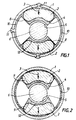
- Figures 1 and 2 illustrate a motor having a fixed inductor exterior according to the present invention and an interior mobile armature.
- the cylinder head made of soft ferromagnetic material
- permanent magnets of hard, non-machined or machined ferromagnetic material briefly with the arrows (3) indicating the direction of the magnetic field.
- the overmolding material (4) contains a soft ferromagnetic product dispersed, represented by the dotted line, in a solid matrix non-magnetic, for example a resin.
- the air gap (5) is good delimited by the overmolding material (4) containing the product soft ferromagnetic and armature (6).
- overmolding was done directly in the cylinder head and we see in the case of Figure 1 that the overmolding material (4) passes through places said cylinder head to form anchor points (11). But in in the case of FIG. 2 the overmolding was carried out outside the cylinder head and the rigid over-molding material / magnets assembly was then introduced into said cylinder head then optionally secured with it by any known means.
- FIG. 3 represents, in an engine of the same type as those of the figures 1 and 2, an inductor according to the invention in which each of the poles is made of several magnets (2) placed side by side, these magnets having more, thanks to the invention, a form of parallelepiped plate lying down.
- Figure 4 shows a case where the cylinder head is in two half-shells (or cylinder arc) (1a) and (1b) and where the overmolding according to the invention coats both the magnets (2) and the two half-shells (1a) and (1b) to get a rigid inductor.
- the junction point between the two half-shells can be located anywhere, relative to the axis of the poles.
- the magnets have been precisely machined from a sintered blank to have a gap with armature of about 0.7mm; they were then put in place and glued into the cylinder head by overmolding with a resin thermosetting so that said magnet-induced air gap is well 0.7mm.
- the overmolding is such that there is no resin veil, covering the polar face of the magnet, located in the air gap. We thus avoid increase the air gap thickness which would be necessary to hold allowance for runout tolerances (cylinder head, armature) or mounting and would lead to a decrease in engine performance.
- non-machined blanks of magnets permanent ones of lower volume then placed in the cylinder head and overmolded using a magnetic permeability composite material 4 based on the same thermosetting resin and in which dispersed iron powder (solid content 40% by volume); the air gap composite / induced overmolding material is the same as in the version standard.
- the thickness of the polar layer is approximately 1mm in places the thinnest, that of the 3mm return zone.
- Version 2 differs from version 1 mainly by an air gap about 0.3mm and thicker magnets but whose volume remains lower than the standard version.
- Table 1 gives the values of the flux, directly linked to the performance of the motors, as a function of the geometric parameters of the magnets and of the air gap value for the different versions.
Landscapes
- Engineering & Computer Science (AREA)
- Power Engineering (AREA)
- Permanent Field Magnets Of Synchronous Machinery (AREA)
- Hard Magnetic Materials (AREA)
- Iron Core Of Rotating Electric Machines (AREA)
- Soft Magnetic Materials (AREA)
- Dynamo-Electric Clutches, Dynamo-Electric Brakes (AREA)
- Coils Or Transformers For Communication (AREA)
Description
Le fait de surmouler les aimants ne permet pas de s'affranchir de ces nécessités, le surmoulage ajoutant par ailleurs, comme cela a déjà été dit, une épaisseur supplémentaire d'entrefer.
Elle a également cherché à en diminuer le coût.
Le matériau de surmoulage enrobe au moins partiellement chacun des aimants, les maintient en place les uns par rapport aux autres et par rapport à la culasse. Le surmoulage est tel que les aimants sont répartis à la surface périphérique de la culasse et qu'il délimite le diamètre de l'inducteur. C'est ce diamètre complété avec l'épaisseur de l'entrefer qui donnera le diamètre de l'induit.
Pour cela on peut réduire au minimum l'épaisseur de cette partie latérale qui ne dépasse pas en général 1 à 4mm. On peut également la supprimer complètement, en laissant cependant subsister par endroits des plots de raccordement en matériau de surmoulage qui contribuent au maintien des aimants et au raccordement de la couche polaire avec la zone de retour. Ces parties latérales ou les plots de raccordement peuvent aussi être réalisés en matériau de surmoulage amagnétique, constituant ainsi un assemblage composite ferromagnétique et amagnétique des aimants dans la culasse.
- à encombrement du moteur constant et à entrefer également constant, à diminuer le volume d'aimant non usiné pour obtenir un flux sensiblement équivalent à celui d'une structure standard de l'art antérieur utilisant des aimants usinés maintenus dans la culasse par collage, surmoulage amagnétique ou fixation mécanique;
- à encombrement du moteur constant, à diminuer l'entrefer ainsi que le volume d'aimant non usiné pour obtenir un flux supérieur à celui de ladite structure, donc à améliorer les performances de la machine tournante;
- à volume d'aimant constant et à entrefer éventuellement réduit, à accroítre considérablement le flux par rapport à ladite structure standard, donc les performances de la machine tournante;
- à encombrement constant et à entrefer éventuellement réduit, à accroítre le volume d'aimant non usiné en augmentant l'angle de couverture d'un pôle. Habituellement, et spécialement dans le cas des aimants frittés anisotropes ayant la forme de tuile canal, les contraintes de fabrication ne permettent pas de réaliser d'un seul tenant et de manière économique, des aimants présentant un angle de couverture important. Ainsi grâce au surmoulage de l'invention un pôle peut être réalisé en accolant bord à bord plusieurs aimants aimantés dans la même direction; ceci permet d'obtenir facilement des angles de couverture très importants, par exemple dépassant aisément 140 à 160°.
- à constituer, selon la méthode précédente, une couronne circulaire complète à l'aide de plusieurs aimants jointifs maintenus par le surmoulage ferromagnétique et aimantés pour obtenir un nombre quelconque de pôles magnétiques;
- à recouvrir au moins partiellement l'autre paroi latérale de la culasse ne comportant pas les aimants, ce qui permet d'utiliser des culasses réalisées à l'aide d'une simple tôle roulée ou emboutie pour obtenir un cylindre non nécessairement fermé et ayant des tolérances géométriques élargies. Dans ce cas, la culasse cylindrique peut même être réalisée à partir d'arcs de cylindres accolés, l'ensemble étant surmoulé simultanément avec les aimants à l'aide du liant ferromagnétique selon l'invention.

Claims (13)
- Inducteur, pour machine tournante électrique, comportant une culasse (1) cylindrique creuse ou pleine sur une paroi latérale de laquelle est fixé au moins un aimant (2) ayant une face polaire située en regard d'un induit (6), caractérisé en ce que l'aimant (2) est fixé à la culasse (1) par un surmoulage enrobant au moins ladite face polaire à l'aide d'un matériau composite de surmoulage (4) comprenant un matériau ferromagnétique dispersé dans un liant solide amagnétique.
- Inducteur selon la revendication 1, caractérisé en ce que la culasse (1) cylindrique est creuse et que le ou les aimants (2) sont fixés sur sa paroi latérale intérieure, l'induit (6) se situant à l'intérieur de l'inducteur.
- Inducteur selon la revendication 1 caractérisé en ce que la culasse (1) cylindrique est pleine ou creuse et que le ou les aimants (2) sont fixés sur sa paroi latérale extérieure, l'induit (6) entourant alors l'inducteur.
- Inducteur selon l'une quelconque des revendications 1 à 3 caractérisé en ce que l'épaisseur d'entrefer (5) est mesurée entre le matériau de surmoulage (4) et l'induit (6).
- Inductucteur selon la revendication 4 caractérisé en ce que l'épaisseur d'entrefer (5) est toujours inférieure à 0,7mm et de préférence d'au plus 0,3mm.
- Inducteur selon l'une quelconque des revendications 1 à 5 caractérisé en ce que l'épaisseur de la couche (12) de matériau de surmoulage (4) recouvrant la face polaire de l'aimant (2) est comprise entre 0,5 et 5mm.
- Inducteur selon l'une quelconque des revendications 1 à 6 caractérisé en ce que le matériau de surmoulage (4) et les aimants (2) forment un ensemble rigide introduit dans la culasse (1) ou obtenu par injection, extrusion, compaction ou moulage dudit matériau dans la culasse.
- Inducteur selon l'une quelconque des revendications 1 à 7 caractérisé en ce que les fuites de flux magnétiques le long des faces latérales des aimants sont réduites au minimum.
- Inducteur selon la revendication 8 caractérisé en ce que l'épaisseur (8) du matériau de surmoulage le long des faces latérales des aimants est inférieure à 5mm.
- Inducteur selon l'une quelconque des revendications 1 à 9 caractérisé en ce que les aimants (2) sont des aimants permanents à base de ferrites, ou de terres rares.
- Inducteur selon l'une quelconque des revendications 1 à 10 caractérisé en ce que le matériau de surmoulage (4) a une perméabilité magnétique supérieure à 2 et de préférence comprise entre 4 et 40.
- Inducteur selon l'une quelconque des revendications 1 à 11 caractérisé en ce que le matériau ferromagnétique dispersé dans le liant amagnétique est un métal ferromagnétique doux contenant au moins un élément du groupe Fe, Co, Ni.
- Inducteur selon l'une quelconque des revendications 1 à 12 caractérisé en ce que le liant solide amagnétique est à base de résine thermodurcissable ou thermoplastique.
Applications Claiming Priority (3)
| Application Number | Priority Date | Filing Date | Title |
|---|---|---|---|
| FR9502009 | 1995-02-16 | ||
| FR9502009A FR2730874B1 (fr) | 1995-02-16 | 1995-02-16 | Inducteur composite pour machines tournantes electriques comportant des aimants permanents frittes enrobes dans un liant ferromagnetique |
| PCT/FR1996/000231 WO1996025785A1 (fr) | 1995-02-16 | 1996-02-13 | Inducteur composite pour machines tournantes electriques comportant des aimants permanents frittes enrobes dans un liant ferromagnetique |
Publications (2)
| Publication Number | Publication Date |
|---|---|
| EP0809878A1 EP0809878A1 (fr) | 1997-12-03 |
| EP0809878B1 true EP0809878B1 (fr) | 1998-10-14 |
Family
ID=9476375
Family Applications (1)
| Application Number | Title | Priority Date | Filing Date |
|---|---|---|---|
| EP96904130A Expired - Lifetime EP0809878B1 (fr) | 1995-02-16 | 1996-02-13 | Inducteur composite pour machines tournantes electriques comportant des aimants permanents frittes enrobes dans un liant ferromagnetique |
Country Status (12)
| Country | Link |
|---|---|
| US (1) | US5861695A (fr) |
| EP (1) | EP0809878B1 (fr) |
| JP (1) | JPH11500597A (fr) |
| KR (1) | KR19980702157A (fr) |
| CN (1) | CN1173950A (fr) |
| AT (1) | ATE172334T1 (fr) |
| BR (1) | BR9607036A (fr) |
| DE (1) | DE69600792T2 (fr) |
| FR (1) | FR2730874B1 (fr) |
| MX (1) | MX9706079A (fr) |
| PL (1) | PL321603A1 (fr) |
| WO (1) | WO1996025785A1 (fr) |
Cited By (2)
| Publication number | Priority date | Publication date | Assignee | Title |
|---|---|---|---|---|
| US6903475B2 (en) | 2001-02-23 | 2005-06-07 | Black & Decker Inc. | Stator assembly with an overmolding that secures magnets to a flux ring and the flux ring to a stator housing |
| US7038343B2 (en) | 2002-02-22 | 2006-05-02 | Black & Decker Inc. | Field assembly for a motor and method of making same |
Families Citing this family (40)
| Publication number | Priority date | Publication date | Assignee | Title |
|---|---|---|---|---|
| JP3017953B2 (ja) * | 1996-07-24 | 2000-03-13 | 株式会社東芝 | 電動機の回転子及びその製造方法 |
| US6097118A (en) * | 1998-10-30 | 2000-08-01 | University Of Chicago | Reluctance apparatus for flywheel energy storage |
| FR2791483B1 (fr) * | 1999-03-22 | 2004-06-25 | Valeo Equip Electr Moteur | Machine tournante comportant des aimants de compositions differentes |
| JP2000324769A (ja) * | 1999-05-13 | 2000-11-24 | Matsushita Electric Ind Co Ltd | ステッピングモータ |
| CN1298091C (zh) * | 2000-01-27 | 2007-01-31 | 布莱克-德克尔公司 | 在熔接环或者电机壳上喷射浇铸的磁铁的固定系统 |
| US6522042B1 (en) | 2000-01-27 | 2003-02-18 | Black & Decker Inc. | Anchoring system for injection molded magnets on a flux ring or motor housing |
| US6522041B1 (en) | 2000-03-08 | 2003-02-18 | Black & Decker Inc. | Permanent magnet motor flux rings |
| US6441522B1 (en) | 2000-03-31 | 2002-08-27 | Coleman Powermate, Inc. | Electromagnetic apparatus employing high permeability low conductivity element |
| JP2002010606A (ja) * | 2000-06-20 | 2002-01-11 | Honda Motor Co Ltd | アウターロータ型ブラシレス直流モータ |
| US6462448B1 (en) | 2000-07-05 | 2002-10-08 | Black & Decker Inc. | Flux ring for an electric motor |
| US20050191788A1 (en) * | 2001-02-15 | 2005-09-01 | Integral Technologies, Inc. | Low cost magnetic brakes and motion control devices manufactured from conductive loaded resin-based materials |
| US7273135B2 (en) * | 2001-02-15 | 2007-09-25 | Integral Technologies, Inc. | Low cost magnetic brakes and motion control devices manufactured from conductive loaded resin-based materials |
| KR100766581B1 (ko) * | 2001-04-03 | 2007-10-15 | 뉴모텍(주) | 열가소성수지가 몰드된 모터 고정자 및 그 제조방법 |
| DE10216476A1 (de) * | 2002-04-13 | 2003-10-23 | Bosch Gmbh Robert | Rotor für eine elektrische Maschine |
| MXPA05006227A (es) * | 2002-12-13 | 2005-08-19 | Black & Decker Inc | Un ensamble de estator con un sobremoldeo que asegura los magnetos a un anillo de flujo y el anillo de flujo a un alojamiento del estator. |
| GB2418544B (en) * | 2002-12-13 | 2006-08-30 | Black & Decker Inc | A stator assembly with an overmolding that secures magnets to a flux ring and the flux ring to a stator housing |
| DE102004002458A1 (de) * | 2004-01-16 | 2005-08-11 | Siemens Ag | Kraftstoff-Fördereinheit |
| US20060127253A1 (en) | 2004-12-10 | 2006-06-15 | Ekberg Andrew M | Inner drive for magnetic drive pump |
| WO2008048486A1 (fr) * | 2006-10-13 | 2008-04-24 | Black & Decker Inc. | Système d'ancrage pour carter de stator à surmoulage, et outil mécanique les comprenant |
| US20110278966A1 (en) * | 2006-10-13 | 2011-11-17 | Black & Decker Inc. | Motor With Overmolded Permanent Magnets |
| DE102007005770A1 (de) * | 2006-12-29 | 2008-07-03 | Robert Bosch Gmbh | Motorische Antriebseinheit für eine Scheibenwischvorrichtung in einem Fahrzeug |
| DE102007014348A1 (de) * | 2007-03-26 | 2008-10-02 | Robert Bosch Gmbh | Magnethalterung für einen elektrischen Motor |
| US7772741B1 (en) * | 2007-11-30 | 2010-08-10 | Rittenhouse Norman P | Wind turbine generator |
| US7579742B1 (en) * | 2008-01-17 | 2009-08-25 | Norman Rittenhouse | High-efficiency parallel-pole molded-magnetic flux channels transverse wound motor-dynamo |
| DE102009031371B4 (de) | 2009-07-01 | 2011-05-26 | Siemens Aktiengesellschaft | Läufer und Verfahren zur Herstellung eines Läufers einer elektrischen Maschine |
| CN102035316B (zh) * | 2009-09-27 | 2015-07-08 | 天津市松正电动汽车技术股份有限公司 | 用于永磁同步电机凸出式转子铁心磁钢的粘贴方式 |
| DE102010043977A1 (de) * | 2010-11-16 | 2012-05-16 | Robert Bosch Gmbh | Elektromotor mit verbessertem Magnethalterring, sowie ein Verfahren zur Herstellung des Magnethalterrings |
| JP5464604B2 (ja) * | 2011-09-20 | 2014-04-09 | シナノケンシ株式会社 | モータ回転子及びその製造方法、並びにインナーロータ型ブラシレスモータ及びその製造方法 |
| US8922087B1 (en) | 2013-08-26 | 2014-12-30 | Norman P Rittenhouse | High efficiency low torque ripple multi-phase permanent magnet machine |
| US20160133364A1 (en) | 2014-11-07 | 2016-05-12 | Ford Global Technologies, Llc | Fixtures and Methods for Forming Aligned Magnetic Cores |
| KR102446182B1 (ko) * | 2015-05-27 | 2022-09-22 | 엘지이노텍 주식회사 | 로터 및 상기 로터를 포함하는 모터 |
| CN105553223B (zh) * | 2015-12-30 | 2018-01-23 | 哈尔滨工业大学 | 一种可自定位的异形磁钢结构的双磁路旋转式音圈电机 |
| CN106936226A (zh) * | 2015-12-30 | 2017-07-07 | 联合汽车电子有限公司 | 电机磁钢、电机和节气门体 |
| FR3069392B1 (fr) * | 2017-07-24 | 2020-11-06 | Valeo Equip Electr Moteur | Rotor a aimants permanents pour moteur electrique et dispositif de pulsion d'air correspondant |
| FR3069391B1 (fr) * | 2017-07-24 | 2021-12-31 | Valeo Equip Electr Moteur | Rotor a aimants permanents pour moteur electrique et dispositif de pulsion d'air correspondant |
| CN109361276A (zh) * | 2018-11-05 | 2019-02-19 | 赣州诚正电机有限公司 | 一种无刷无框稀土永磁电机 |
| US12131864B2 (en) | 2020-10-08 | 2024-10-29 | Deere & Company | Transformer with integral inductor |
| FR3118346B1 (fr) * | 2020-12-17 | 2023-10-20 | Renault Sas | Elément à pôles magnétiques pour rotor de machine électrique à flux axial |
| JP7760923B2 (ja) * | 2022-01-28 | 2025-10-28 | 株式会社デンソー | 回転電機の回転子、及び回転子の製造方法 |
| IT202300020907A1 (it) * | 2023-10-09 | 2025-04-09 | Cebi Motors S P A | Struttura di motore elettrico particolarmente per applicazioni automotive |
Family Cites Families (7)
| Publication number | Priority date | Publication date | Assignee | Title |
|---|---|---|---|---|
| US3899702A (en) * | 1971-12-09 | 1975-08-12 | Singer Co | Torquer armature |
| US3789250A (en) * | 1972-02-04 | 1974-01-29 | Ford Motor Co | Permanent magnet dynamoelectric machine |
| DE2835441A1 (de) * | 1978-08-12 | 1980-02-28 | Vacuumschmelze Gmbh | Verfahren zum herstellen eines aus ebenen segmenten aufgebauten schalenmagneten |
| JPS56112868A (en) * | 1980-02-06 | 1981-09-05 | Matsushita Electric Ind Co Ltd | Small-sized dc motor |
| JPS60131055A (ja) * | 1983-12-16 | 1985-07-12 | Hitachi Ltd | 磁石式直流機の固定子とその製造方法 |
| FR2617343B1 (fr) * | 1987-06-23 | 1993-05-21 | Valeo | Pole inducteur a aimant permanent, et stator de machine tournante electrique pourvu de tels poles |
| FR2617344B1 (fr) * | 1987-06-23 | 1993-05-21 | Valeo | Stator de machine tournante electrique a aimants permanents |
-
1995
- 1995-02-16 FR FR9502009A patent/FR2730874B1/fr not_active Expired - Fee Related
-
1996
- 1996-02-13 JP JP8524711A patent/JPH11500597A/ja not_active Ceased
- 1996-02-13 AT AT96904130T patent/ATE172334T1/de not_active IP Right Cessation
- 1996-02-13 US US08/875,109 patent/US5861695A/en not_active Expired - Lifetime
- 1996-02-13 PL PL96321603A patent/PL321603A1/xx unknown
- 1996-02-13 KR KR1019970705552A patent/KR19980702157A/ko not_active Withdrawn
- 1996-02-13 BR BR9607036A patent/BR9607036A/pt not_active Application Discontinuation
- 1996-02-13 CN CN96191916A patent/CN1173950A/zh active Pending
- 1996-02-13 EP EP96904130A patent/EP0809878B1/fr not_active Expired - Lifetime
- 1996-02-13 WO PCT/FR1996/000231 patent/WO1996025785A1/fr not_active Ceased
- 1996-02-13 DE DE69600792T patent/DE69600792T2/de not_active Expired - Lifetime
- 1996-02-13 MX MX9706079A patent/MX9706079A/es unknown
Cited By (6)
| Publication number | Priority date | Publication date | Assignee | Title |
|---|---|---|---|---|
| US6903475B2 (en) | 2001-02-23 | 2005-06-07 | Black & Decker Inc. | Stator assembly with an overmolding that secures magnets to a flux ring and the flux ring to a stator housing |
| US6983529B2 (en) | 2001-02-23 | 2006-01-10 | Black & Decker Inc. | Stator assembly with an overmolding that secures magnets to a flux ring and the flux ring to a stator housing |
| US7088024B2 (en) | 2001-02-23 | 2006-08-08 | Black & Decker Inc. | Field assembly for a motor and method of making same |
| US7091642B2 (en) | 2001-02-23 | 2006-08-15 | Black & Decker Inc. | Field assembly for a motor and method of making same |
| US7119469B2 (en) | 2001-02-23 | 2006-10-10 | Black & Decker Inc. | Stator assembly with an overmolding that secures magnets to a flux ring and the flux ring to a stator housing |
| US7038343B2 (en) | 2002-02-22 | 2006-05-02 | Black & Decker Inc. | Field assembly for a motor and method of making same |
Also Published As
| Publication number | Publication date |
|---|---|
| JPH11500597A (ja) | 1999-01-12 |
| US5861695A (en) | 1999-01-19 |
| WO1996025785A1 (fr) | 1996-08-22 |
| PL321603A1 (en) | 1997-12-08 |
| CN1173950A (zh) | 1998-02-18 |
| KR19980702157A (ko) | 1998-07-15 |
| DE69600792T2 (de) | 1999-05-27 |
| FR2730874B1 (fr) | 1997-03-21 |
| DE69600792D1 (de) | 1998-11-19 |
| BR9607036A (pt) | 1997-11-04 |
| EP0809878A1 (fr) | 1997-12-03 |
| MX9706079A (es) | 1998-02-28 |
| ATE172334T1 (de) | 1998-10-15 |
| FR2730874A1 (fr) | 1996-08-23 |
Similar Documents
| Publication | Publication Date | Title |
|---|---|---|
| EP0809878B1 (fr) | Inducteur composite pour machines tournantes electriques comportant des aimants permanents frittes enrobes dans un liant ferromagnetique | |
| EP3602742B1 (fr) | Structure d'aimant à plusieurs aimants unitaires intégrés dans un maillage | |
| EP3738199B1 (fr) | Moteur ou génératrice électromagnétique à deux rotors et quatre stators et système de refroidissement intégré | |
| EP4264781B1 (fr) | Element a poles magnetiques, comprenant un ensemble de plusieurs aimants unitaires, pour rotor de machine electrique a flux axial | |
| EP0313514B1 (fr) | Procédé de fabrication d'un stator sans rainures pour moteur électrique et moteur électrique comprenant un stator fabriqué selon le procédé | |
| EP0587685A1 (fr) | Moteur pas-a-pas ou synchrone economique. | |
| EP3729609B1 (fr) | Stator de moteur ou generatrice electromagnetique avec support individuel de bobinage encliquete sur une dent associee | |
| FR2958466A1 (fr) | Machine electrique tournante synchrone a aimants permanents et concentration de flux | |
| EP3857677A1 (fr) | Rotor a flux axial aux aimants et corps en couches de composite avec fibres d'orientations differentes | |
| FR2927481A1 (fr) | Procede de montage d'un pole magnetique et rotor associe. | |
| FR2617344A1 (fr) | Stator de machine tournante electrique a aimants permanents | |
| EP4364280B1 (fr) | Procede de fabrication d'un element a poles magnetiques | |
| FR3077414A1 (fr) | Aimant unitaire a configuration ovoide et structure d'aimant a plusieurs aimants unitaires | |
| FR2617345A1 (fr) | Stator de machine tournante electrique a aimants permanents, et pole inducteur destine a ce stator | |
| FR3001841A1 (fr) | Moteur ou generatrice electromagnetique polyentrefers a aimants permanents et elements a bobinage sans fer | |
| FR3132803A1 (fr) | Procédé de fabrication d’un rotor pour machine électrique | |
| FR2617343A1 (fr) | Pole inducteur a aimant permanent, et stator de machine tournante electrique pourvu de tels poles | |
| FR2958467A1 (fr) | Machine electrique tournante synchrone a aimants permanents et concentration de flux | |
| FR3077413A1 (fr) | Aimant unitaire avec formes en retrait destinees a faire partie de zones de contact entre des aimants adjacents | |
| FR2786041A1 (fr) | Stator inducteur pour machine electrique tournante, notamment pour moteur electrique | |
| FR2497021A1 (en) | Electro-motor for timepiece - has punched rotor comprising magnetic material with plastic binder | |
| EP3465891A1 (fr) | Rotor de machine électrique tournante muni d'aimants en terre rare à faible taux de dysprosium | |
| FR3080715A1 (fr) | Stator d'une machine electrique tournante comprenant un aimant a volume optimise | |
| FR2924280A1 (fr) | Stator pour machine electrique tournante, notamment un demarreur | |
| FR3038788A1 (fr) | Rotor surmoule de machine electrique tournante. |
Legal Events
| Date | Code | Title | Description |
|---|---|---|---|
| PUAI | Public reference made under article 153(3) epc to a published international application that has entered the european phase |
Free format text: ORIGINAL CODE: 0009012 |
|
| 17P | Request for examination filed |
Effective date: 19970707 |
|
| AK | Designated contracting states |
Kind code of ref document: A1 Designated state(s): AT CH DE ES FR GB IE IT LI NL |
|
| GRAG | Despatch of communication of intention to grant |
Free format text: ORIGINAL CODE: EPIDOS AGRA |
|
| 17Q | First examination report despatched |
Effective date: 19971219 |
|
| GRAG | Despatch of communication of intention to grant |
Free format text: ORIGINAL CODE: EPIDOS AGRA |
|
| GRAH | Despatch of communication of intention to grant a patent |
Free format text: ORIGINAL CODE: EPIDOS IGRA |
|
| GRAH | Despatch of communication of intention to grant a patent |
Free format text: ORIGINAL CODE: EPIDOS IGRA |
|
| GRAA | (expected) grant |
Free format text: ORIGINAL CODE: 0009210 |
|
| AK | Designated contracting states |
Kind code of ref document: B1 Designated state(s): AT CH DE ES FR GB IE IT LI NL |
|
| PG25 | Lapsed in a contracting state [announced via postgrant information from national office to epo] |
Ref country code: NL Free format text: LAPSE BECAUSE OF FAILURE TO SUBMIT A TRANSLATION OF THE DESCRIPTION OR TO PAY THE FEE WITHIN THE PRESCRIBED TIME-LIMIT Effective date: 19981014 Ref country code: ES Free format text: THE PATENT HAS BEEN ANNULLED BY A DECISION OF A NATIONAL AUTHORITY Effective date: 19981014 Ref country code: AT Free format text: LAPSE BECAUSE OF FAILURE TO SUBMIT A TRANSLATION OF THE DESCRIPTION OR TO PAY THE FEE WITHIN THE PRESCRIBED TIME-LIMIT Effective date: 19981014 |
|
| REF | Corresponds to: |
Ref document number: 172334 Country of ref document: AT Date of ref document: 19981015 Kind code of ref document: T |
|
| REG | Reference to a national code |
Ref country code: CH Ref legal event code: EP |
|
| REF | Corresponds to: |
Ref document number: 69600792 Country of ref document: DE Date of ref document: 19981119 |
|
| REG | Reference to a national code |
Ref country code: IE Ref legal event code: FG4D Free format text: FRENCH |
|
| GBT | Gb: translation of ep patent filed (gb section 77(6)(a)/1977) |
Effective date: 19981218 |
|
| NLV1 | Nl: lapsed or annulled due to failure to fulfill the requirements of art. 29p and 29m of the patents act | ||
| PG25 | Lapsed in a contracting state [announced via postgrant information from national office to epo] |
Ref country code: IE Free format text: LAPSE BECAUSE OF NON-PAYMENT OF DUE FEES Effective date: 19990820 |
|
| PLBE | No opposition filed within time limit |
Free format text: ORIGINAL CODE: 0009261 |
|
| STAA | Information on the status of an ep patent application or granted ep patent |
Free format text: STATUS: NO OPPOSITION FILED WITHIN TIME LIMIT |
|
| 26N | No opposition filed | ||
| REG | Reference to a national code |
Ref country code: IE Ref legal event code: FD4D |
|
| PG25 | Lapsed in a contracting state [announced via postgrant information from national office to epo] |
Ref country code: LI Free format text: LAPSE BECAUSE OF NON-PAYMENT OF DUE FEES Effective date: 20000229 Ref country code: CH Free format text: LAPSE BECAUSE OF NON-PAYMENT OF DUE FEES Effective date: 20000229 |
|
| REG | Reference to a national code |
Ref country code: CH Ref legal event code: PL |
|
| REG | Reference to a national code |
Ref country code: GB Ref legal event code: IF02 |
|
| PGFP | Annual fee paid to national office [announced via postgrant information from national office to epo] |
Ref country code: GB Payment date: 20040126 Year of fee payment: 9 |
|
| PGFP | Annual fee paid to national office [announced via postgrant information from national office to epo] |
Ref country code: FR Payment date: 20040211 Year of fee payment: 9 |
|
| PG25 | Lapsed in a contracting state [announced via postgrant information from national office to epo] |
Ref country code: IT Free format text: LAPSE BECAUSE OF NON-PAYMENT OF DUE FEES;WARNING: LAPSES OF ITALIAN PATENTS WITH EFFECTIVE DATE BEFORE 2007 MAY HAVE OCCURRED AT ANY TIME BEFORE 2007. THE CORRECT EFFECTIVE DATE MAY BE DIFFERENT FROM THE ONE RECORDED. Effective date: 20050213 Ref country code: GB Free format text: LAPSE BECAUSE OF NON-PAYMENT OF DUE FEES Effective date: 20050213 |
|
| GBPC | Gb: european patent ceased through non-payment of renewal fee |
Effective date: 20050213 |
|
| PG25 | Lapsed in a contracting state [announced via postgrant information from national office to epo] |
Ref country code: FR Free format text: LAPSE BECAUSE OF NON-PAYMENT OF DUE FEES Effective date: 20051031 |
|
| REG | Reference to a national code |
Ref country code: FR Ref legal event code: ST Effective date: 20051031 |
|
| PGFP | Annual fee paid to national office [announced via postgrant information from national office to epo] |
Ref country code: DE Payment date: 20100217 Year of fee payment: 15 |
|
| REG | Reference to a national code |
Ref country code: DE Ref legal event code: R119 Ref document number: 69600792 Country of ref document: DE Effective date: 20110901 |
|
| PG25 | Lapsed in a contracting state [announced via postgrant information from national office to epo] |
Ref country code: DE Free format text: LAPSE BECAUSE OF NON-PAYMENT OF DUE FEES Effective date: 20110901 |