EP0810037A2 - Distributeur de liquide à pompe - Google Patents
Distributeur de liquide à pompe Download PDFInfo
- Publication number
- EP0810037A2 EP0810037A2 EP97302720A EP97302720A EP0810037A2 EP 0810037 A2 EP0810037 A2 EP 0810037A2 EP 97302720 A EP97302720 A EP 97302720A EP 97302720 A EP97302720 A EP 97302720A EP 0810037 A2 EP0810037 A2 EP 0810037A2
- Authority
- EP
- European Patent Office
- Prior art keywords
- plunger
- wall
- piston
- pump
- stem
- Prior art date
- Legal status (The legal status is an assumption and is not a legal conclusion. Google has not performed a legal analysis and makes no representation as to the accuracy of the status listed.)
- Granted
Links
Images

Classifications
-
- B—PERFORMING OPERATIONS; TRANSPORTING
- B05—SPRAYING OR ATOMISING IN GENERAL; APPLYING FLUENT MATERIALS TO SURFACES, IN GENERAL
- B05B—SPRAYING APPARATUS; ATOMISING APPARATUS; NOZZLES
- B05B11/00—Single-unit hand-held apparatus in which flow of contents is produced by the muscular force of the operator at the moment of use
- B05B11/01—Single-unit hand-held apparatus in which flow of contents is produced by the muscular force of the operator at the moment of use characterised by the means producing the flow
- B05B11/10—Pump arrangements for transferring the contents from the container to a pump chamber by a sucking effect and forcing the contents out through the dispensing nozzle
- B05B11/1001—Piston pumps
- B05B11/1023—Piston pumps having an outlet valve opened by deformation or displacement of the piston relative to its actuating stem
-
- B—PERFORMING OPERATIONS; TRANSPORTING
- B05—SPRAYING OR ATOMISING IN GENERAL; APPLYING FLUENT MATERIALS TO SURFACES, IN GENERAL
- B05B—SPRAYING APPARATUS; ATOMISING APPARATUS; NOZZLES
- B05B11/00—Single-unit hand-held apparatus in which flow of contents is produced by the muscular force of the operator at the moment of use
- B05B11/01—Single-unit hand-held apparatus in which flow of contents is produced by the muscular force of the operator at the moment of use characterised by the means producing the flow
- B05B11/10—Pump arrangements for transferring the contents from the container to a pump chamber by a sucking effect and forcing the contents out through the dispensing nozzle
- B05B11/1042—Components or details
- B05B11/1059—Means for locking a pump or its actuation means in a fixed position
-
- B—PERFORMING OPERATIONS; TRANSPORTING
- B05—SPRAYING OR ATOMISING IN GENERAL; APPLYING FLUENT MATERIALS TO SURFACES, IN GENERAL
- B05B—SPRAYING APPARATUS; ATOMISING APPARATUS; NOZZLES
- B05B11/00—Single-unit hand-held apparatus in which flow of contents is produced by the muscular force of the operator at the moment of use
- B05B11/01—Single-unit hand-held apparatus in which flow of contents is produced by the muscular force of the operator at the moment of use characterised by the means producing the flow
- B05B11/10—Pump arrangements for transferring the contents from the container to a pump chamber by a sucking effect and forcing the contents out through the dispensing nozzle
- B05B11/1042—Components or details
- B05B11/1043—Sealing or attachment arrangements between pump and container
- B05B11/1046—Sealing or attachment arrangements between pump and container the pump chamber being arranged substantially coaxially to the neck of the container
- B05B11/1047—Sealing or attachment arrangements between pump and container the pump chamber being arranged substantially coaxially to the neck of the container the pump being preassembled as an independent unit before being mounted on the container
Definitions
- This invention relates generally to pump dispenser having a reduced number of parts, the dispenser having its plunger containing a discharge spout locked in a up position to avoid leakage during intervals of shipping and storage and to function as a childproof and safety feature.
- Many pump dispensers are known as having lock-up and/or lock-down plunger features of various styles and structures. Many of such locking plunger dispensers provide for relative rotation between longitudinally extending ribs and grooves into misalignment and alignment of inoperative and operative positions of the plunger. However, many of such known dispensers require separate, rotatable lock collars to effect a match and mismatch between the ribs and grooves, thereby requiring at least one additional molded part which adds to the cost of the dispenser.
- U.S. Patent 4,162,746, commonly owned herewith, discloses a dispenser having a lock-up plunger requiring a rotatable lock ring in the form of an annular sleeve for matching and mismatching ribs on the piston stem with grooves at an inner wall of the lock ring.
- U.S. Patent 3,489,322 discloses another type plunger lock-up dispenser eliminating the need for a lock ring and instead providing for a match and mismatch between ribs and grooves upon relative rotation of the plunger head.
- the discharge spout is not made part of the head but is rather formed on a separate part which snap-fits together with the container closure, thereby significantly adding to the cost of the package.
- plunger lock-up dispensers are not positively retained in the locked position such that the plunger head can be unintentionally rendered operative upon only a slight backoff from the misaligned position.
- a dispensing package is dropped or nudged liquid product could easily leak from the spout even after the user has locked the plunger in place.
- a child of tender years can quickly figure out a way to unlock the plunger head thereby either creating a mess or an unsafe condition.
- Many pump dispensers are of the type having a lost motion between the piston and piston stem, the latter being hollow and having lateral discharge ports which are uncovered upon a relative shifting movement of the stem upon plunger actuation.
- a container vent passage is closed in the at-rest condition of the plunger by an upper seal of the piston cup which operates within the pump cylinder. It is undesirable for the piston cup to be used in such manner for the opening and closing of the container vent passage as the seal could deteriorate thereby causing leakage.
- the pump dispenser according to the invention has a locking sleeve fixed within the pump body, a pump plunger having a discharge spout being rotatable in opposite directions about its central axis, extending through coaxial openings in the container closure and locking sleeve, and being disposed for reciprocation between lowered and spring biased raised positions.
- the locking sleeve has an upper edge wall with a upstanding limit stop at one end and a longitudinal groove at an opposite end of that wall.
- a detent on the wall adjacent the groove and spaced from the limit stop delimits an abutment shoulder with which a radially extending projection on the piston stem engages for locking the plunger in its raised position. Such projection is positively cradled between the detent and the limit stop.
- the pump body and the container closure may be of a one-piece molded construction to minimize the number of parts required for the pump plunger.
- a hollow piston stem is fixed to the plunger and extends through a piston cup for relative shifting movement upon plunger actuation to uncover lateral discharge ports to open the discharge.
- An inner upstanding sleeve on the piston cup seals against a lower edge of the locking sleeve for sealing a container vent passage closed in the at-rest position of the plunger.
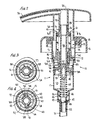
- the pump dispenser according to the invention is generally designated 10 in Figures 1 and 2 as having a port 11 which may be of unitary molded construction forming a pump body 12 and a container closure 13.
- the closure has internal threads 14 for engagement with the external threads on the bottle neck of a container (not shown) for mounting the dispenser in place.
- An outer skirt 15 surrounding the closure may be provided for aesthetic purposes.
- the pump body includes upper and lower cylindrical portions 16 and 17, the latter having a slightly smaller diameter and forming a pump cylinder.
- a locking sleeve 18 is fixed within upper portion 16 of the pump body as by snap action between an annular flange 19 of the sleeve and an annular rib 21 integral with portion 16. Relative movement of the sleeve about its central axis is inhibited by the provision of tiny radial projections 22 (Fig. 1) engaging longitudinal grooves 23 extending along the inside of upper portion 16.
- Plunger head 24 of the dispenser has a smooth contoured upper surface 25 which defines a smooth bearing surface for the fingers or palm of the hand of the operator.
- the plunger head has an integrally formed spout 26 in communication with a hollow piston stem 27 defining a discharge passage 28.
- the piston stem is fixedly secured to the plunger head as by the provision of a snap bead 29, a plurality of longitudinally extending ribs 31 on the stem engaging mating grooves in sleeve 32 of the head to prevent relative rotation about the central axis of the parts.
- a lower portion 33 of the locking sleeve has an inner diameter substantially equal to the outer major diameter of the piston stem, and has on its surface one or more longitudinal grooves 34 defining a vent path.
- the lower end of the piston stem is constricted as at 35 so as to define an annular shoulder 36.
- One or more discharge ports 37 are provided in the wall of the constricted portion which extends through the central opening of a piston cup 38.
- the piston cup has a lower chevron seal 42 in sealing engagement with the wall of the pump cylinder, and has an upper chevron seal 43 likewise in sealing engagement with the wall of the pump cylinder.
- a piston return spring 44 extends between bead 39 and shoulders 45 of spring centering ribs 46 located within throat portion 47 of the pump body which houses an inlet ball check valve 48 shown in engagement with its valve seat 49.
- a dip tube 51 connected to a nipple 52 extending from throat section 47 extends into the container (not shown). Ribs 46 and the lowermost most turn of the return spring form a ball cage for the inlet ball check valve.
- shoulder 36 is spaced a predetermined axial distance from flange 41 such that, upon depression of the plunger head, the piston stem shifts relative to the piston cup exposing discharge ports 37 to the product in pump chamber 53 such that continued depression of the head reciprocates the piston within its cylinder pressurizing the liquid product in the pump chamber forcing it through the discharge ports, discharge passage 28 and outwardly through the spout, as in a known manner.
- the return spring shifts the piston stem relative to the piston back to its Fig. 2 position closing the discharge ports and returning the piston to its Fig. 2 position whereupon the pump chamber volume expands such that a corresponding drop in pressure therein suctions product from the container up through the dip tube and the unseated inlet ball check valve and into the pump chamber.
- a container vent port 54 is provided in the wall of pump cylinder 17 above chevron seal 43 in the at-rest position of the plunger.
- An internal, upstanding sleeve 55 on the piston engages the underside of lower portion 33 of the locking sleeve and has an inner diameter substantially equal to the outer diameter of piston stem so as to seal the vent grooves 34 closed in the Fig. 2 position. Also, sleeve 55 maintains the axial spacing between shoulder 36 and flange 41 in the at-rest position of the plunger.
- vent grooves 34 are opened establishing a vent passage to the atmosphere from inside the container via vent port 54. And, by spacing the chevron seals of the piston cup away from vent port 54 so as to avoid sliding contact, any scoring of the piston seals is avoided. Also, no portion of the piston seals engages the locking sleeve or any other element for maintaining the vent grooves closed in the at-rest position of the plunger, as in prior art constructions. Thus, the somewhat delicate piston seal is thereby preserved from damage and scoring which could otherwise cause leakage.
- the plunger lock-up feature according to the invention is facilitated by the provision of a pair of opposing edge walls 56 lying in a plane perpendicular to the central axis of sleeve 18.
- An upstanding limit stop 57 having a longitudinally extending edge 58 is located at one end of each edge wall 56.
- At the other end of each edge wall is a longitudinal extending groove 59, and a detent 60 is provided on each edge wall 56 adjacent each groove 59 and spaced from edge 58 to thereby define edge wall 56 as an abutment shoulder.
- the piston stem has a pair of opposing projections 61 for matching and mismatching with grooves 59 upon a relative rotation of the plunger head to that of the locking sleeve.
- the plunger head is simply rotated about its central axis through about 90° in the direction of "CLOSE” arrow of Fig. 5, opposite that of the "OPEN” arrow, such that projections 61 override detent 60 and engage shoulders 56 (see Fig. 4) as limited in the circumferential travel of the projections by longitudinal edges 58 of the limit stops.
- edges 58 and detents 60 present a cradling action for projections 51, the detent positively retaining the projections in place under the bias of the return spring.
- any slight nudge of the plunger head in the OPEN direction will not overcome the positive retention presented by the detents. Even if the dispensing package is dropped, it is unlikely that the plunger head will be forced to rotate into its OPEN position due to the positive retention feature of the invention.
- the operator is able to sense the tracking movement of the projections 61 about the detents, such that the detents likewise provide an indexing function for the operator.
- the locking sleeve could include a single abutment shoulder, detent and limit stop and groove for a single projection 61, without departing from the invention. It is therefore to be understood that within the scope of the appended claims the invention may be practiced otherwise than as specifically described.
Landscapes
- Closures For Containers (AREA)
- Reciprocating Pumps (AREA)
- Containers And Packaging Bodies Having A Special Means To Remove Contents (AREA)
- Devices For Dispensing Beverages (AREA)
Applications Claiming Priority (2)
| Application Number | Priority Date | Filing Date | Title |
|---|---|---|---|
| US08/655,923 US5615806A (en) | 1996-05-31 | 1996-05-31 | Plunger lock-up dispenser |
| US655923 | 1996-05-31 |
Publications (3)
| Publication Number | Publication Date |
|---|---|
| EP0810037A2 true EP0810037A2 (fr) | 1997-12-03 |
| EP0810037A3 EP0810037A3 (fr) | 1998-04-08 |
| EP0810037B1 EP0810037B1 (fr) | 2003-02-12 |
Family
ID=24630946
Family Applications (1)
| Application Number | Title | Priority Date | Filing Date |
|---|---|---|---|
| EP97302720A Expired - Lifetime EP0810037B1 (fr) | 1996-05-31 | 1997-04-21 | Distributeur de liquide à pompe |
Country Status (14)
| Country | Link |
|---|---|
| US (1) | US5615806A (fr) |
| EP (1) | EP0810037B1 (fr) |
| JP (1) | JP3263921B2 (fr) |
| KR (1) | KR100485940B1 (fr) |
| CN (1) | CN1084645C (fr) |
| AR (1) | AR001762A1 (fr) |
| AU (1) | AU716595B2 (fr) |
| BR (1) | BR9700613A (fr) |
| CA (1) | CA2205857C (fr) |
| DE (1) | DE69718965T2 (fr) |
| ES (1) | ES2187723T3 (fr) |
| HU (1) | HU222272B1 (fr) |
| PL (1) | PL182348B1 (fr) |
| TW (1) | TW333513B (fr) |
Cited By (3)
| Publication number | Priority date | Publication date | Assignee | Title |
|---|---|---|---|---|
| DE19756442A1 (de) * | 1997-12-18 | 1999-06-24 | Pfeiffer Erich Gmbh & Co Kg | Spender für Medien |
| WO2004041047A3 (fr) * | 2002-11-04 | 2004-08-26 | Kimberly Clark Co | Pompe distributrice de liquide visqueux |
| KR100485940B1 (ko) * | 1996-05-31 | 2005-08-11 | 칼마르 인코포레이티드 | 액체펌프분배기 |
Families Citing this family (102)
| Publication number | Priority date | Publication date | Assignee | Title |
|---|---|---|---|---|
| USD389406S (en) | 1996-02-13 | 1998-01-20 | Sar S.P.A. | Dispenser cap for flasks and bottles |
| US5971215A (en) * | 1996-09-06 | 1999-10-26 | The Procter & Gamble Company | Dispensing pump lock |
| USD399745S (en) | 1996-12-13 | 1998-10-20 | Sar S.P.A. | Dispenser cap for bottles |
| IT1292958B1 (it) * | 1997-02-28 | 1999-02-11 | Taplast Spa | Perfezionamento a pompa dosatrice per l'erogazione di sostanze liquide o dense da contenitori. |
| USD392887S (en) | 1997-04-03 | 1998-03-31 | Calmar Inc. | Dispenser head and collar |
| USD441654S1 (en) | 1997-04-18 | 2001-05-08 | Owens-Illinois Closure Inc. | Liquid dispenser |
| USD399746S (en) | 1997-06-13 | 1998-10-20 | The Procter & Gamble Company | Dispensing spout |
| DE19727356B4 (de) | 1997-06-27 | 2006-04-20 | Ing. Erich Pfeiffer Gmbh | Spender für Medien |
| US5878916A (en) * | 1997-10-03 | 1999-03-09 | Dejonge; Stuart W. | Metered dosage undirectional tracked pumped dispenser |
| US5899363A (en) * | 1997-12-22 | 1999-05-04 | Owens-Illinois Closure Inc. | Pump dispenser having a locking system with detents |
| US6045008A (en) | 1998-04-30 | 2000-04-04 | Calmar-Monturas, S.A. | Fluid pump dispenser |
| ES2152814B1 (es) * | 1998-04-30 | 2001-08-16 | Saint Gobain Calmar Sa | Dispensador de fluidos. |
| USD424441S (en) * | 1999-02-12 | 2000-05-09 | Taplast Spa | Dosing cap |
| FR2790743B1 (fr) * | 1999-03-08 | 2001-06-01 | Sofab | Dispositif pour l'assemblage d'une pompe sur le col d'un recipient a collerette d'accrochage |
| USD424938S (en) * | 1999-07-06 | 2000-05-16 | Owens-Illinois Closure Inc. | Actuator for pump dispenser for lotion or the like |
| USD427527S (en) * | 1999-07-06 | 2000-07-04 | Owens-Illinois Closure Inc. | Actuator for pump dispenser for lotion or the like |
| USD436863S1 (en) | 1999-08-30 | 2001-01-30 | Calmar Inc. | Dispenser head |
| USD434984S (en) * | 1999-08-30 | 2000-12-12 | Calmar Inc. | Dispenser head |
| US6651851B2 (en) * | 1999-09-15 | 2003-11-25 | Technical Concepts, Llc | System and method for dispensing soap |
| CN100464165C (zh) * | 1999-10-01 | 2009-02-25 | 科技概念有限公司 | 挤出肥皂液的系统和方法 |
| BR0101069A (pt) | 2000-03-15 | 2001-11-06 | Saint Gobain Calmar Sa | Distribuidor de bomba de fluìdo |
| USD452822S1 (en) | 2000-03-22 | 2002-01-08 | Airspray International B.V. | Foam dispenser |
| USD438468S1 (en) | 2000-06-09 | 2001-03-06 | Calmar Inc. | Dispenser head |
| USD438798S1 (en) | 2000-06-09 | 2001-03-13 | Calmar Inc. | Dispenser head |
| USD438113S1 (en) | 2000-06-09 | 2001-02-27 | Calmar Inc. | Dispenser head |
| USD458539S1 (en) | 2000-12-19 | 2002-06-11 | Dieter Bakic Design S.R.L. | Pump head |
| US6601735B2 (en) * | 2001-01-19 | 2003-08-05 | Valois S.A. | Fluid dispenser device |
| USD457061S1 (en) | 2001-03-14 | 2002-05-14 | Peter J. Walters | Dispensing cap for finger pump |
| US6695171B2 (en) | 2002-02-12 | 2004-02-24 | Seaquistperfect Dispensing Foreign, Inc. | Pump dispenser |
| ES2235564B1 (es) * | 2002-05-27 | 2007-02-01 | Pecoso, S.L. | Valvula dosificadora de substancias fluidas. |
| DE03727511T1 (de) * | 2002-05-27 | 2005-07-14 | Pecoso S.L. | Dosierventil für Flüssigkeiten |
| DE10259275A1 (de) * | 2002-12-17 | 2004-07-01 | Eric Schliemann | Dosiervorrichtung |
| DE20304731U1 (de) * | 2003-03-25 | 2003-06-26 | MegaPlast GmbH & Co. KG, 78052 Villingen-Schwenningen | Dosierpumpe aus Kunststoff |
| US7051903B2 (en) * | 2003-09-30 | 2006-05-30 | Kimberly-Clark Worldwide, Inc. | Viscous liquid dispenser having leak prevention device |
| ITVI20040169A1 (it) * | 2004-07-09 | 2004-10-09 | Taplast Spa | Unita' per l'erogazione di fluidi o miscele e relativo dispositivo di erogazione |
| US7654418B2 (en) * | 2004-08-30 | 2010-02-02 | Rieke Corporation | Airless dispensing pump |
| US7367476B2 (en) | 2004-08-30 | 2008-05-06 | Rieke Corporation | Airless dispensing pump with tamper evidence features |
| DE102004046768A1 (de) * | 2004-09-24 | 2006-04-06 | Seaquist Perfect Dispensing Gmbh | Vorrichtung zur Ausgabe, insbesondere Zerstäubung, einer vorzugsweise kosmetischen Flüssigkeit |
| US20060113329A1 (en) * | 2004-11-29 | 2006-06-01 | Seaquisperfect Dispensing Foreign, Inc. | Dispenser with lock |
| US7249692B2 (en) | 2004-11-29 | 2007-07-31 | Seaquistperfect Dispensing Foreign, Inc. | Dispenser with lock |
| DE102005013409B4 (de) * | 2005-03-23 | 2009-04-02 | Meadwestvaco Calmar Gmbh | Handkolbenpumpe mit blockierbarem Ausgabekopf zur Ausgabe von fluiden Substanzen |
| USD548596S1 (en) | 2005-07-05 | 2007-08-14 | Airspray International, B.V. | Dispenser for liquid soap |
| USD536973S1 (en) | 2005-07-05 | 2007-02-20 | Airspray International B.V. | Dispenser for liquid soap |
| USD528912S1 (en) | 2005-07-05 | 2006-09-26 | Airspray International B.V. | Dispenser for liquid soap |
| USD546188S1 (en) * | 2005-07-27 | 2007-07-10 | Reckitt & Colman (Overseas) Limited | Jar |
| DE602005023667D1 (de) * | 2005-09-16 | 2010-10-28 | Rexam Dispensing Sys | Zwischenverriegelungsring |
| USD527258S1 (en) * | 2006-01-23 | 2006-08-29 | Colgate-Palmolive Company | Dispenser spout |
| CN100494008C (zh) * | 2006-06-15 | 2009-06-03 | 丁要武 | 弹簧外置式乳液泵 |
| US7735688B2 (en) * | 2006-10-10 | 2010-06-15 | Meadwestvaco Calmar, Inc. | Rotating collar and locking and venting closure connector for an air foaming pump dispenser |
| US7931172B2 (en) * | 2007-04-16 | 2011-04-26 | Roy Kuo | Pump dispenser used with lotion bottle |
| MX2009011797A (es) | 2007-04-30 | 2009-11-13 | Colgate Palmolive Co | Conjunto de bomba para relleno de recipiente. |
| WO2009127651A1 (fr) * | 2008-04-15 | 2009-10-22 | Rpc Bramlage Gmbh | Distributeur |
| FR2932400B1 (fr) * | 2008-06-17 | 2011-11-18 | Valois Sas | Dispositif de distribution de produit fluide |
| KR101239903B1 (ko) * | 2009-04-08 | 2013-03-06 | 제주대학교 산학협력단 | 펌프형 용기 |
| ITMI20090577A1 (it) * | 2009-04-09 | 2010-10-10 | Nettuno S R L | Erogatore dosatore particolarmente per prodotti lavamani quali saponi liquidi, gel, creme anche con abrasivi e simili. |
| CN101658827B (zh) * | 2009-09-11 | 2011-12-14 | 黄建壮 | 乳液泵旋转伸缩式喷头 |
| DE102010063318A1 (de) * | 2010-12-17 | 2012-06-21 | Robert Bosch Gmbh | Hydraulikvorrichtung, insbesondere Niederdruckspeicher mit einem Verschlusselement |
| US8814007B2 (en) | 2010-12-31 | 2014-08-26 | Medline Industries, Inc. | Dispenser with directional flow controlling flange and corresponding systems |
| ITVI20110230A1 (it) * | 2011-08-05 | 2013-02-06 | Stefano Doria | Dispositivo per l'erogazione di fluidi e liquidi |
| KR200471184Y1 (ko) * | 2012-02-02 | 2014-02-11 | 주식회사 하나 | 풀림방지 구조를 갖는 화장품 용기 |
| USD678064S1 (en) | 2012-02-10 | 2013-03-19 | Arminak & Associates, Llc | Pump actuator |
| KR101496970B1 (ko) * | 2012-04-20 | 2015-03-02 | (주)연우 | 비강세척수 분사용기 |
| CN102700843B (zh) * | 2012-05-21 | 2014-05-07 | 王雅灿 | 可调式喷头装置 |
| KR101325527B1 (ko) * | 2012-09-11 | 2013-11-07 | (주)연우 | 안전버튼구조가 구비된 디스펜서 용기 |
| US9897475B2 (en) | 2012-10-02 | 2018-02-20 | Brightwell Dispensers Limited | Dispensing device with indicator member |
| GB2506609B (en) * | 2012-10-02 | 2015-08-26 | Brightwell Dispensers Ltd | Dispensing device |
| TWM455414U (zh) * | 2013-01-28 | 2013-06-21 | Well Max Beauty Lab Co Ltd | 具有壓頭之容器 |
| US20150090738A1 (en) * | 2013-09-27 | 2015-04-02 | Emsar S.P.A | Actuating device for a dispensing pump of a dispenser |
| CN103708093B (zh) * | 2013-12-13 | 2016-08-17 | 中山市美捷时包装制品有限公司 | 一种双弹簧乳液泵 |
| US10065205B2 (en) * | 2014-04-23 | 2018-09-04 | Israel Olegnowicz | Integrated lock for atomizer |
| EP3169444B1 (fr) | 2014-07-14 | 2021-01-06 | Rieke Packaging Systems Limited | Distributeurs à pompe |
| CN105736277B (zh) * | 2014-12-10 | 2018-06-19 | 富泰华工业(深圳)有限公司 | 流体供给装置 |
| CN104590703B (zh) * | 2015-01-20 | 2017-10-17 | 金华职业技术学院 | 一种带有止压环的按压泵 |
| CN105396721A (zh) * | 2015-10-23 | 2016-03-16 | 上海应用技术学院 | 带自锁结构的按压喷雾器喷头 |
| NL2015724B1 (en) * | 2015-11-04 | 2017-05-24 | Gab Eng & Dev B V | Storage holder for a dispenser. |
| GB201520997D0 (en) * | 2015-11-27 | 2016-01-13 | Rieke Packaging Systems Ltd | Dispensers |
| CN105480550A (zh) * | 2015-12-25 | 2016-04-13 | 中山市美捷时包装制品有限公司 | 一种稳定型弹簧外置自锁泵 |
| USD792218S1 (en) * | 2016-01-04 | 2017-07-18 | Living Fountain Plastic Industrial Co., Ltd. | Dispensing pump head |
| JP6670671B2 (ja) * | 2016-04-28 | 2020-03-25 | 株式会社吉野工業所 | 吐出器 |
| GB201608596D0 (en) * | 2016-05-16 | 2016-06-29 | Rieke Packaging Systems Ltd | Pump dispensers |
| CN106005723B (zh) * | 2016-07-01 | 2017-12-15 | 中山市美捷时包装制品有限公司 | 弹簧外置的标准化多功能自锁与螺牙锁液体分配泵 |
| CN107021293A (zh) * | 2017-04-13 | 2017-08-08 | 中山市美捷时包装制品有限公司 | 一种泵系统锁紧机构及外置弹簧卡扣式泵系统 |
| CN106882474A (zh) * | 2017-04-13 | 2017-06-23 | 中山市美捷时包装制品有限公司 | 一种用于泵系统的锁紧机构及内置弹簧卡扣式泵系统 |
| CN111032230B (zh) * | 2017-06-12 | 2022-05-13 | 斯勒冈分配系统公司 | 泵锁定保持结构及使用其的方法 |
| US10493478B2 (en) * | 2017-07-14 | 2019-12-03 | Armin Arminak | Hand pump with folding nozzle |
| CN111094142B (zh) * | 2017-09-20 | 2021-10-29 | 株式会社吉野工业所 | 喷出器 |
| IT201800007700A1 (it) * | 2018-07-31 | 2020-01-31 | Aptar Italia Spa | Un dispenser per l'erogazione di un fluido |
| CN109649821A (zh) * | 2018-11-14 | 2019-04-19 | 杭州余杭振华日化玻璃有限公司 | 一种外置弹簧式泵芯 |
| CN111016748A (zh) * | 2020-01-06 | 2020-04-17 | 重庆飞适动力汽车座椅部件有限公司 | 自锁式按压内触发解锁组件 |
| CN111268272A (zh) * | 2020-02-21 | 2020-06-12 | 中山市美捷时包装制品有限公司 | 一种全塑自锁泵 |
| US11453535B2 (en) | 2020-05-08 | 2022-09-27 | Berry Global, Inc. | Selectively openable closure for a container |
| US11332279B2 (en) | 2020-09-25 | 2022-05-17 | World Club Supply Corporation | Liquid dispenser apparatus |
| JP1716860S (ja) * | 2020-12-17 | 2022-06-07 | 抽出用ポンプのヘッド | |
| CN112660600A (zh) * | 2020-12-23 | 2021-04-16 | 中山市美捷时包装制品有限公司 | 一种外置弹簧卡扣式按压泵结构 |
| USD1005115S1 (en) * | 2021-06-14 | 2023-11-21 | ChemCore Zrt. | Bottle with cap |
| USD1024770S1 (en) * | 2021-07-26 | 2024-04-30 | Silgan Dispensing Systems Corporation | Pump head |
| USD994498S1 (en) | 2021-08-13 | 2023-08-08 | World Club Supply Corporation | Liquid dispenser |
| USD996975S1 (en) | 2021-08-13 | 2023-08-29 | World Club Supply Corporation | Liquid dispenser apparatus |
| USD1010444S1 (en) | 2021-08-13 | 2024-01-09 | World Club Supply Corp. | Combined pump top and skirt |
| IT202100025532A1 (it) * | 2021-10-07 | 2023-04-07 | Silgan Dispensing Systems Milano S R L | Pompa ad azionamento manuale |
| USD1115526S1 (en) * | 2023-07-25 | 2026-03-03 | Shenzhen Huayouwei Technology Co., Ltd. | Dispensing pump head |
| CN118237193A (zh) * | 2024-05-09 | 2024-06-25 | 广东美捷时控股股份有限公司 | 一种全塑可回收按压泵 |
Family Cites Families (26)
| Publication number | Priority date | Publication date | Assignee | Title |
|---|---|---|---|---|
| US3187960A (en) * | 1964-05-08 | 1965-06-08 | Sterling Drug Inc | Non-metallic pump dispenser |
| US3608788A (en) * | 1967-12-15 | 1971-09-28 | Mitani Valve Co Ltd | Fluid-dispensing pump |
| US3489322A (en) * | 1968-02-21 | 1970-01-13 | Acu Tech Corp | Dispenser pump |
| US3500761A (en) * | 1968-07-01 | 1970-03-17 | Cook Chem Co | Control valve for hand pumps |
| US3590691A (en) * | 1969-06-26 | 1971-07-06 | Cook Chem Co | Locking clip for hand pumps |
| US3601290A (en) * | 1969-07-11 | 1971-08-24 | Gillette Co | Aerosol dispenser actuator |
| US3724726A (en) * | 1972-01-05 | 1973-04-03 | Lion Fat Oil Co Ltd | Pump for spraying |
| US3827606A (en) * | 1973-06-27 | 1974-08-06 | Diamond Int Corp | Pump immobilizing means |
| US4155489A (en) * | 1976-12-20 | 1979-05-22 | Wolf Steiman | Leakproof pump for hand-held dispensers |
| US4162746A (en) * | 1977-06-22 | 1979-07-31 | Diamond International Corporation | Liquid dispenser locking means |
| US4420096A (en) * | 1977-08-22 | 1983-12-13 | Ethyl Products Company | Child-resistant actuator cover |
| IT1134954B (it) * | 1981-01-07 | 1986-08-20 | Sar Spa | Pompa ad azionamento manuale per la erogazione sotto pressione di sostanze liquide e/o dense racchiuse in un contenitore sul quale la pompa e' montata |
| IT8221773U1 (it) * | 1982-05-04 | 1983-11-04 | S A R S P A | Pompetta a mano con cappuccio erogatore vincolabile in posizione abbassata, per l'erogazione di sostanze fluide. |
| FR2530586A1 (fr) * | 1982-07-26 | 1984-01-27 | Aerosol Inventions Dev | Pompe manuelle pour la distribution de produits liquides ou pateux a partir de petits recipients |
| KR840001093A (ko) * | 1982-08-16 | 1984-03-28 | 데쯔야 다다 | 디스펜서(dispenser) |
| JPS6057832U (ja) * | 1983-09-27 | 1985-04-22 | ヤマハ発動機株式会社 | 回転を係止する装置 |
| US4589574A (en) * | 1983-11-30 | 1986-05-20 | Realex Corporation | Dispensing pump having collar-to-body anti-rotation interlock |
| DE3666030D1 (en) * | 1985-03-14 | 1989-11-09 | Mega Prod Verpack Marketing | Metering pump with a pumping bellow for bottles or the like |
| US4991746A (en) * | 1989-07-07 | 1991-02-12 | Emson Research Inc. | Modular pump having a locking rotatable sleeve |
| FR2669379A1 (fr) * | 1990-11-21 | 1992-05-22 | Promotion Rech Innovation Tec | Pompe doseuse pour produits liquides. |
| US5134898A (en) * | 1991-03-07 | 1992-08-04 | Hewlett-Packard Company | Rotary tactile feedback apparatus |
| JPH0563660U (ja) * | 1992-02-12 | 1993-08-24 | 東洋製罐株式会社 | ポンプ |
| US5335830A (en) * | 1992-10-21 | 1994-08-09 | Bespak Plc | Pump dispenser for lotions and/or large doses of product |
| DE9418511U1 (de) * | 1994-08-03 | 1995-03-02 | Fa. Bintz, 21073 Hamburg | Kolbenpumpe, insbesondere Handkolbenpumpe |
| US5615806A (en) * | 1996-05-31 | 1997-04-01 | Calmar-Albert Gmbh | Plunger lock-up dispenser |
| AUPR057900A0 (en) * | 2000-10-05 | 2000-10-26 | Aristocrat Technologies Australia Pty Limited | Player choice game feature |
-
1996
- 1996-05-31 US US08/655,923 patent/US5615806A/en not_active Expired - Fee Related
-
1997
- 1997-04-21 DE DE69718965T patent/DE69718965T2/de not_active Expired - Fee Related
- 1997-04-21 EP EP97302720A patent/EP0810037B1/fr not_active Expired - Lifetime
- 1997-04-21 HU HU9700788A patent/HU222272B1/hu not_active IP Right Cessation
- 1997-04-21 ES ES97302720T patent/ES2187723T3/es not_active Expired - Lifetime
- 1997-04-28 BR BR9700613A patent/BR9700613A/pt not_active IP Right Cessation
- 1997-05-05 AR ARP970101847 patent/AR001762A1/es active IP Right Grant
- 1997-05-12 TW TW086106314A patent/TW333513B/zh active
- 1997-05-13 KR KR1019970018630A patent/KR100485940B1/ko not_active Expired - Fee Related
- 1997-05-20 CN CN97104294A patent/CN1084645C/zh not_active Expired - Fee Related
- 1997-05-21 AU AU23556/97A patent/AU716595B2/en not_active Ceased
- 1997-05-22 CA CA002205857A patent/CA2205857C/fr not_active Expired - Fee Related
- 1997-05-28 PL PL97320242A patent/PL182348B1/pl not_active IP Right Cessation
- 1997-06-02 JP JP14379097A patent/JP3263921B2/ja not_active Expired - Fee Related
Cited By (3)
| Publication number | Priority date | Publication date | Assignee | Title |
|---|---|---|---|---|
| KR100485940B1 (ko) * | 1996-05-31 | 2005-08-11 | 칼마르 인코포레이티드 | 액체펌프분배기 |
| DE19756442A1 (de) * | 1997-12-18 | 1999-06-24 | Pfeiffer Erich Gmbh & Co Kg | Spender für Medien |
| WO2004041047A3 (fr) * | 2002-11-04 | 2004-08-26 | Kimberly Clark Co | Pompe distributrice de liquide visqueux |
Also Published As
| Publication number | Publication date |
|---|---|
| HUP9700788A3 (en) | 1998-06-29 |
| BR9700613A (pt) | 1998-09-29 |
| ES2187723T3 (es) | 2003-06-16 |
| HUP9700788A2 (hu) | 1998-05-28 |
| HU9700788D0 (en) | 1997-06-30 |
| DE69718965D1 (de) | 2003-03-20 |
| CA2205857C (fr) | 2002-10-22 |
| KR970074640A (ko) | 1997-12-10 |
| PL182348B1 (pl) | 2001-12-31 |
| MX9702781A (es) | 1997-11-29 |
| EP0810037B1 (fr) | 2003-02-12 |
| CN1167215A (zh) | 1997-12-10 |
| HU222272B1 (hu) | 2003-05-28 |
| HK1002267A1 (en) | 1998-08-14 |
| CN1084645C (zh) | 2002-05-15 |
| AU2355697A (en) | 1997-12-04 |
| EP0810037A3 (fr) | 1998-04-08 |
| TW333513B (en) | 1998-06-11 |
| AU716595B2 (en) | 2000-03-02 |
| KR100485940B1 (ko) | 2005-08-11 |
| CA2205857A1 (fr) | 1997-11-30 |
| AR001762A1 (es) | 1997-12-10 |
| JPH1061544A (ja) | 1998-03-03 |
| JP3263921B2 (ja) | 2002-03-11 |
| US5615806A (en) | 1997-04-01 |
| PL320242A1 (en) | 1997-12-08 |
| DE69718965T2 (de) | 2003-08-28 |
Similar Documents
| Publication | Publication Date | Title |
|---|---|---|
| US5615806A (en) | Plunger lock-up dispenser | |
| US6006949A (en) | Manually operated reciprocating liquid pump with sealing vent opening | |
| US4589573A (en) | Head depression type dispenser | |
| EP0755305B1 (fr) | Pompe a liquide a mouvement alternatif et actionnement manuel | |
| US3949906A (en) | Liquid dispensing pump selectively sealable against leakage | |
| US5405057A (en) | Manually actuated pump | |
| EP0953381B1 (fr) | Distributeur à pompe pour fluides | |
| KR100212442B1 (ko) | 펌프 분배기 | |
| CA2369546C (fr) | Contenant distributeur de liquide a fermeture automatique | |
| US4458832A (en) | Liquid dispensing pump | |
| US4511065A (en) | Manually actuated pump having pliant piston | |
| US3779464A (en) | Manually actuated liquid spraying device | |
| US7735688B2 (en) | Rotating collar and locking and venting closure connector for an air foaming pump dispenser | |
| IE50719B1 (en) | Liquid dispenser | |
| US4050860A (en) | Spray pump assembly | |
| US5938081A (en) | Container and cap closure | |
| US5715973A (en) | Manually operated fluid pump for dispensing lotion and the like | |
| US20070045349A1 (en) | Liquid dispensing pump with shifting liquid piston | |
| IL114679A (en) | Reaching pump | |
| US4034900A (en) | Spray pump assembly | |
| US5775547A (en) | Lotion dispensing pump with sealing plug for sealing pump chamber | |
| EP0759327A1 (fr) | Couvercle de base pour pulvérisateur à gachette | |
| HK1002267B (en) | Liquid pump dispenser | |
| US3446478A (en) | Aerosol valve actuator button | |
| MXPA97002781A (en) | Automatic distributor of embolo with cerrad |
Legal Events
| Date | Code | Title | Description |
|---|---|---|---|
| PUAI | Public reference made under article 153(3) epc to a published international application that has entered the european phase |
Free format text: ORIGINAL CODE: 0009012 |
|
| AK | Designated contracting states |
Kind code of ref document: A2 Designated state(s): BE DE ES FR GB IT NL SE |
|
| PUAL | Search report despatched |
Free format text: ORIGINAL CODE: 0009013 |
|
| AK | Designated contracting states |
Kind code of ref document: A3 Designated state(s): BE DE ES FR GB IT NL SE |
|
| 17P | Request for examination filed |
Effective date: 19980522 |
|
| 17Q | First examination report despatched |
Effective date: 20010515 |
|
| GRAG | Despatch of communication of intention to grant |
Free format text: ORIGINAL CODE: EPIDOS AGRA |
|
| GRAG | Despatch of communication of intention to grant |
Free format text: ORIGINAL CODE: EPIDOS AGRA |
|
| GRAH | Despatch of communication of intention to grant a patent |
Free format text: ORIGINAL CODE: EPIDOS IGRA |
|
| GRAH | Despatch of communication of intention to grant a patent |
Free format text: ORIGINAL CODE: EPIDOS IGRA |
|
| GRAA | (expected) grant |
Free format text: ORIGINAL CODE: 0009210 |
|
| AK | Designated contracting states |
Designated state(s): BE DE ES FR GB IT NL SE |
|
| REG | Reference to a national code |
Ref country code: GB Ref legal event code: FG4D |
|
| REF | Corresponds to: |
Ref document number: 69718965 Country of ref document: DE Date of ref document: 20030320 Kind code of ref document: P |
|
| REG | Reference to a national code |
Ref country code: SE Ref legal event code: TRGR |
|
| REG | Reference to a national code |
Ref country code: ES Ref legal event code: FG2A Ref document number: 2187723 Country of ref document: ES Kind code of ref document: T3 |
|
| ET | Fr: translation filed | ||
| PLBE | No opposition filed within time limit |
Free format text: ORIGINAL CODE: 0009261 |
|
| STAA | Information on the status of an ep patent application or granted ep patent |
Free format text: STATUS: NO OPPOSITION FILED WITHIN TIME LIMIT |
|
| 26N | No opposition filed |
Effective date: 20031113 |
|
| PGFP | Annual fee paid to national office [announced via postgrant information from national office to epo] |
Ref country code: NL Payment date: 20070424 Year of fee payment: 11 |
|
| PGFP | Annual fee paid to national office [announced via postgrant information from national office to epo] |
Ref country code: ES Payment date: 20070426 Year of fee payment: 11 |
|
| PGFP | Annual fee paid to national office [announced via postgrant information from national office to epo] |
Ref country code: SE Payment date: 20070427 Year of fee payment: 11 |
|
| PGFP | Annual fee paid to national office [announced via postgrant information from national office to epo] |
Ref country code: BE Payment date: 20070515 Year of fee payment: 11 |
|
| PGFP | Annual fee paid to national office [announced via postgrant information from national office to epo] |
Ref country code: DE Payment date: 20070531 Year of fee payment: 11 |
|
| PGFP | Annual fee paid to national office [announced via postgrant information from national office to epo] |
Ref country code: GB Payment date: 20070425 Year of fee payment: 11 |
|
| PGFP | Annual fee paid to national office [announced via postgrant information from national office to epo] |
Ref country code: IT Payment date: 20070521 Year of fee payment: 11 |
|
| PGFP | Annual fee paid to national office [announced via postgrant information from national office to epo] |
Ref country code: FR Payment date: 20070417 Year of fee payment: 11 |
|
| BERE | Be: lapsed |
Owner name: *CALMAR INC. Effective date: 20080430 |
|
| EUG | Se: european patent has lapsed | ||
| GBPC | Gb: european patent ceased through non-payment of renewal fee |
Effective date: 20080421 |
|
| NLV4 | Nl: lapsed or anulled due to non-payment of the annual fee |
Effective date: 20081101 |
|
| PG25 | Lapsed in a contracting state [announced via postgrant information from national office to epo] |
Ref country code: NL Free format text: LAPSE BECAUSE OF NON-PAYMENT OF DUE FEES Effective date: 20081101 Ref country code: DE Free format text: LAPSE BECAUSE OF NON-PAYMENT OF DUE FEES Effective date: 20081101 |
|
| REG | Reference to a national code |
Ref country code: FR Ref legal event code: ST Effective date: 20081231 |
|
| PG25 | Lapsed in a contracting state [announced via postgrant information from national office to epo] |
Ref country code: BE Free format text: LAPSE BECAUSE OF NON-PAYMENT OF DUE FEES Effective date: 20080430 |
|
| PG25 | Lapsed in a contracting state [announced via postgrant information from national office to epo] |
Ref country code: FR Free format text: LAPSE BECAUSE OF NON-PAYMENT OF DUE FEES Effective date: 20080430 |
|
| REG | Reference to a national code |
Ref country code: ES Ref legal event code: FD2A Effective date: 20080422 |
|
| PG25 | Lapsed in a contracting state [announced via postgrant information from national office to epo] |
Ref country code: GB Free format text: LAPSE BECAUSE OF NON-PAYMENT OF DUE FEES Effective date: 20080421 |
|
| PG25 | Lapsed in a contracting state [announced via postgrant information from national office to epo] |
Ref country code: ES Free format text: LAPSE BECAUSE OF NON-PAYMENT OF DUE FEES Effective date: 20080422 |
|
| PG25 | Lapsed in a contracting state [announced via postgrant information from national office to epo] |
Ref country code: IT Free format text: LAPSE BECAUSE OF NON-PAYMENT OF DUE FEES Effective date: 20080421 |
|
| PG25 | Lapsed in a contracting state [announced via postgrant information from national office to epo] |
Ref country code: SE Free format text: LAPSE BECAUSE OF NON-PAYMENT OF DUE FEES Effective date: 20080422 |